
Subscribe to Our Youtube Channel
Related Manuals for janitza 800-CT8-LP


Summary of Contents for janitza 800-CT8-LP
- Page 1 800-CT8-LP current measuring module Expansion module for the UMG 801 User manual and technical data Janitza electronics GmbH Vor dem Polstück 6 D-35633 Lahnau Support tel. +49 6441 9642-22 Email: info@janitza.de www.janitza.de...
- Page 2 800-CT8-LP module www.janitza.de 800-CT8-LP current measuring module for UMG 801 Doc. no.: 2.053.093.0.a Date: 05/2023 The German version is the original edition of the documentation...
- Page 3 Nonetheless, we wish to point out that updates of this document are not always possible at the same time as technical refinements are implemented in our products. Please see our website under www.janitza.de for the current version. Please see our website under www.janitza.de for the current version.
-
Page 4: Table Of Contents
Hazards when handling the device, components and modules Electrically qualified personnel Warranty in the event of damage Safety information for handling current transformers 3. Product description 800-CT8-LP current measuring module Incoming goods inspection Intended use Overview of module functions EU/UKCA Declaration of Conformity... - Page 5 UMG 801 basic device homepage 9. Operation and button functions of the basic device with module Operation and button functions of the basic device with the 800-CT8-LP module Module-relevant menu items of the basic device with 800-CT8-LP modules 10. Module-relevant configurations 10.1...
- Page 6 800-CT8-LP module www.janitza.de 14. Dismounting 15. Module exchange/error cases 15.1 Module replacement 15.2 Modules - Error cases 16. Service and maintenance 16.1 Repair 16.2 Service 16.3 Device adjustment 16.4 Calibration interval 16.5 Firmware update 16.6 Procedure in the event of a malfunction 16.7...
- Page 7 800-CT8-LP module...
-
Page 8: Information On The Devices And The User Manual
We ask for your understanding for these simpli- · This user manual applies to the 800-CT8-LP mod- fications. ule. Separate validities and distinctions are marked. · First make sure you have read and understood the usage information accompanying the product. -
Page 9: Defective Device/Disposal
· When doing so, please bear the terms for transpor- tation in mind. INFORMATION Please return defective or damaged devices, modules or components to Janitza electronics GmbH in ac- cordance with the shipping instructions for air or road freight (complete with accessories). Observe special regulations for devices with built-in... -
Page 10: Safety
800-CT8-LP module www.janitza.de Safety The chapter on Safety contains information which 2.3 Product safety must be observed to ensure your personal safety The devices, components and modules reflect and avoid material damage. current engineering practice and accepted safety standards, but hazards can arise nonetheless. -
Page 11: Hazards When Handling The Device, Components And Modules
· Hazardous voltages can be present in all cir- · Do not use Janitza meters, modules or compo- cuitry parts that are connected to the power nents for critical switching, control or protection supply. -
Page 12: Electrically Qualified Personnel
For limits indicated can lead to material damage or injury, Janitza measurement devices, modules and compo- up to and including death. nents, use only "transformers for measuring pur- ·... - Page 13 800-CT8-LP module CAUTION Risk of injury or damage to the meter due to high measured currents/measured voltages at the connections of the current transformers! High measurement currents can cause temperatures of up to 80 °C (176 °F) on the connections of the current transformers ·...
-
Page 14: Product Description
800-CT8-LP module www.janitza.de Product description 3.1 800-CT8-LP current measuring module INFORMATION The current measuring module When setting up your meter and module topology, · extends the functional range of the basic device note that to include additional current measuring channels ·... -
Page 15: Incoming Goods Inspection
3.4 Overview of module functions · no longer functions despite an intact power supply, · was subjected to extended periods of unfavorable Functions of the 800-CT8-LP module: conditions (e.g. storage outside of the permissible · 8 current measurement inputs (2 groups of 4) climate thresholds without adjustment to the room ·... -
Page 16: Eu/Ukca Declaration Of Conformity
Code of Federal Regulations, Title 47, Part 15, Sub- part B - Unintentional Radiators. 3.7 Transformers It is not permitted to use the outputs of Janitza measurement devices, components and modules for switching protective devices or protective relays! Use only "Current transformers for measuring purposes"... -
Page 17: Operating Concept
® als. A list of parameters and Modbus addresses with data on your basic device with module is available for you as a download at www.janitza.de. 3.11 GridVis network analysis software ® With the GridVis software, you have the perfect tool ®... -
Page 18: Mounting
- Ground and short circuit! - Cover or block off adjacent live parts! · Only operate the UMG 801 basic device belong- ing to the 800-CT8-LP module with a supply voltage of 24 V! Observe the technical specifi- cations in the usage information of your basic device. - Page 19 DIN rail Bus connector Fig.: Side view of the UMG 801 and 800-CT8-LP module 4. To couple the bus connectors (devices), push the contacts of your module bus connector into the sockets of the basic device bus connector (or into the sockets of the connected module).
- Page 20 UMG 801 End bracket End bracket DIN rail Fig.: Front view of the UMG 801 with coupled 800-CT8-LP module (installation example) 5. After successfully coupling the bus connectors (of the devices), mount end brackets to the se- ries of meters and modules.
-
Page 21: Checking The Module's Communication
800-CT8-LP module 4.2 Checking the module’s communication 4.3 Faulty module communication After installing your module, check the function Error after starting the basic device with module: of the communication between the basic device and the module using the display on the basic... -
Page 22: Connections/Controls
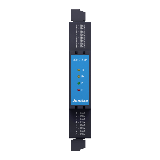
800-CT8-LP module www.janitza.de Connections/controls INFORMATION The current measuring module is supplied with the necessary screw terminals and bus connectors (Jan- Bus interface) for connection to the basic device or other modules. Item Designation Description 4 current measurement inputs in the... -
Page 23: Module Markings - Rating Plate
Made in Germany • www.janitza.com www.janitza.de 800-CT8-LP module Janitza electronics GmbH Vor dem Polstück 6 35633 Lahnau / Germany Module markings – rating plate 800-CON • 5231203 Made in Germany • www.janitza.com T8-LP Janitza electronics GmbH Vor dem Polstück 6... -
Page 24: Installation
800-CT8-LP module www.janitza.de Installation 7.1 Current measurement with the module WARNING Your 800-CT8-LP module in combination with the Risk of injury due to high currents and high electri- basic device (UMG 801): cal voltages! · Measures current exclusively via low-power current Severe bodily injury or death can result from: ·... -
Page 25: Terminal 1 - Connections
· Do not use the outputs of the Janitza measure- ment devices or their components for switching Consumer protective devices or protective relays! Do not use “Transformers for protection purposes”! -
Page 26: Module Identification / Diagnostics On The Basic Device
800-CT8-LP module www.janitza.de 7.3 Module identification / Diagnostics on the 7.3.1 Entry Identify all modules basic device · In the Diagnostics window, use buttons 2 “5” and 5 “6” to select the menu item Identify all modules INFORMATION and confirm with button 3 Enter. -
Page 27: Entry Identify One Module
800-CT8-LP module LED status of the module in operation: 7.3.2 Entry Identify one module · In the Diagnostics window, use buttons 2 “5” and 5 “6” to select the menu item Identify one module and confirm with button 3 Enter. -
Page 28: Module Communication / Pc Connection
800-CT8-LP module www.janitza.de Module communication / PC connection 8.1 Module communication 8.2.1 Module handling in the GridVis software ® Configure your current measuring module via The interface of the GridVis power grid monitoring ® the display and the buttons on your basic device software indicates in graphical form the modules (UMG 801). - Page 29 800-CT8-LP module...
-
Page 30: Operation And Button Functions Of The Basic Device With Module
PC. 800-CT8-LP modules in the measurement device display. The menu items in the measurement device display · Include up to 10 module entries with the respective INFORMATION item numbers. - Page 31 800-CT8-LP module Power Energy Power summary Active energy Basic device 1-4 Basic device 1-4 Basic device 5-8 Basic device 5-8 1. Module 1-4 1. Module 1-4 1. Module 5-8 1. Module 5-8 10. Module 1-4 10. Module 1-4 10. Module 5-8 10.
- Page 32 800-CT8-LP module www.janitza.de Configuration Diagnostics Ethernet config. A Identify all modules IP configuration Duration IP address Confirm Netmask Identify ei10. Module Gateway Position Ethernet config. B Duration IP configuration Confirm IP address System Information Netmask Basic device Gateway Serial number...
- Page 33 800-CT8-LP module...
-
Page 34: Module-Relevant Configurations
800-CT8-LP module www.janitza.de 10. Module-relevant configurations 10.1 LP current transformer configuration on the · The Current transformers window appears. basic device Current transformer In this user manual, the term "current transformer" is used for special transformers for the proportional conversion of currents of large amperages to directly... -
Page 35: Lp Current Transformer Configuration In The Gridvis ® Software
GridVis software (see Fig. below). A description of ® the configuration can be found in the online help or in the tutorials for the software. Fig. LP current transformer configuration "Module 1" (800-CT8-LP) in the GridVis software. ®... -
Page 36: Lp Current Transformer Configuration Via The Device Homepage Of The Umg 801
Another option to configure the LP current trans- be found in the UMG 801 user manual. formers on the module is via the device homepage of the basic device. Fig. LP current transformer configuration "Module 1" (800-CT8-LP) on the device homepage of the basic device. - Page 37 800-CT8-LP module...
-
Page 38: Module-Relevant Measuring Displays
800-CT8-LP module www.janitza.de 11. Module-relevant measuring displays INFORMATION The following measured value and instrument displays of the basic device do not show a concrete application and may differ depending on the connection of your basic device with modules and the measuring environ- ment! ·... - Page 39 800-CT8-LP module Menu (Current) Menu Home Phasor diagram Voltage Current Power Submenu (Current) Current Current Current Modul 1. Module 1-4 Basic device 1-4 Value Avg. Max. Current THD I Basic device 5-8 1.940A 1.940A 1.940A 1. Module 1-4 1.940A 1.940A...
- Page 40 800-CT8-LP module www.janitza.de Menu (Power) Menu Home Phasor diagram Voltage Current Power Submenu (Power summary) Power summary 1. Module 1-4 Power Power summary Power summary Basic device 1-4 Active power Basic device 5-8 0.10kW -0.00kvar 0.19kVA Reactive power 0.10kW -0.00kvar 0.19kVA...
- Page 41 800-CT8-LP module Submenu (Reactive power) Power Reactive power Reactive power 1. Module 1-4 Power summary Basic device 1-4 Value Avg. Active power Basic device 5-8 -0.02kvar -0.01kvar Reactive power -0.02kvar -0.01kvar 1. Module Apparent power -0.02kvar -0.01kvar 1. Module Power factor -0.06kvar...
- Page 42 800-CT8-LP module www.janitza.de Submenu (Power factor) Power Power factor Power factor 1. Module 1-4 Power summary Basic device 1-4 cos(phi) Power factor Active power Basic device 5-8 0.984 0.513 Reactive power 1. Module 0.985 0.513 Apparent power 0.985 0.513 1. Module Power factor 0.985...
- Page 43 800-CT8-LP module Submenu (Reactive energy) Energy Reactive energy Reactive energy 1. Module 1-4 Active energy Basic device 1-4 Sum L1..L3 Reactive energy Basic device 5-8 50.2 kvarh Inductive 0.9kvarh Apparent energy 50.2 kvarh 1. Module 50.2 kvarh 1. Module Capacitive 0.9kvarh...
- Page 44 800-CT8-LP module www.janitza.de Menu (Diagnostics) Diagnostic Identify all modules Menu Identify all modules Multifunctional channels Identify single module Duration Digital I/O-Status Confirm Configuration Diagnostic System information The display "Identify all modules with duration and confirm". Identify single module Diagnostic Identify all modules...
- Page 45 800-CT8-LP module...
-
Page 46: Device Views
18 mm/0.71 in View from left Bottom view Top view 26 mm/1.02 in 36 mm/1.42 in 14 mm/0.55 in 6 mm/0.24 in Rear view Communication bus connector to the 800-CT8-LP module Sockets for Sockets for further modules 800-CT8-LP module Connector for the bus connector Contacts for the UMG 801 or connected modules... -
Page 47: Technical Data
800-CT8-LP module 13. Technical data 13.1 Technical specifications General Net weight (with plug-in terminals) 73 g (0.16 lb) W = 18 mm (w = 0.71 in), H = 90 mm (h = 3.54 in), Device dimensions D = 76 mm (d = 2.99 in) Mounting orientation As desired · TS 35/7.5 according to EN 60715 Fastening/mounting - · TS 35/10 Suitable DIN rails - (35 mm / 1.38 in) ·... -
Page 48: Performance Characteristics Of Functions
E (error – initialization and malfunction) fault. INFORMATION Detailed information on the functions and data of the basic device can be found in the usage information included with the basic device or available for download at www.janitza.de! 13.2 Performance characteristics of functions Function Symbol Accuracy class - 333 mV nominal voltage... -
Page 49: Dismounting
INFORMATION Secure it against being switched on! Check to be sure it is de-energized! Ground and short circuit! Observe the following: After dismounting the 800-CT8-LP module, the Cover or block off adjacent live parts! GridVis software deactivates the corresponding ®... -
Page 50: Module Exchange/Error Cases
800-CT8-LP module www.janitza.de 15. Module exchange/error cases Before replacing a module, please refer to Sect. “14. 15.1 Module replacement Dismounting” on p. 49 and „4. Mounting“ on p. 18. A module must be exchanged, for example to replace a defective module with an intact module ATTENTION in your meter and module topology. -
Page 51: Modules - Error Cases
2 s and the blink interval starts again from the beginning (repetition loop). 3. If these measures are unsuccessful, please con- The number of blinks indicates the following error tact our support team (www.janitza.de). states: Number of Error state blinks No error - normal operation. -
Page 52: Service And Maintenance
800-CT8-LP module www.janitza.de 16. Service and maintenance Your measurement device (module/component) goes INFORMATION through various safety tests and is marked with a seal before delivery. If a measurement device (mod- This user manual describes the modules and pro- ule/component) is opened, the safety tests must be vides information on the operation of the modules repeated. -
Page 53: Information On Saving Measured Values And Configuration Data
800-CT8-LP module 16.8 Information on saving measured values and configuration data INFORMATION The basic device stores the following measured val- ues every 5 minutes at the latest: · Min. / max. / average values · Energy values (work values) The basic device saves configuration data... - Page 54 Janitza electronics GmbH Vor dem Polstück 6 D-35633 Lahnau Support tel. +49 6441 9642-22 Email: info@janitza.de www.janitza.de...
Need help?
Do you have a question about the 800-CT8-LP and is the answer not in the manual?
Questions and answers