Sign In
Upload
Manuals
Brands
janitza Manuals
Control Unit
800 Series
janitza 800 Series Modular Power Analyzer Manuals
Manuals and User Guides for janitza 800 Series Modular Power Analyzer. We have
4
janitza 800 Series Modular Power Analyzer manuals available for free PDF download: User Manual And Technical Data
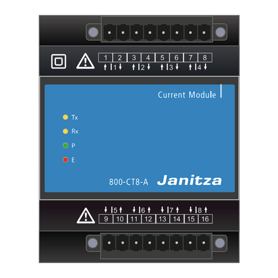
janitza 800 Series User Manual And Technical Data (60 pages)
current measuring module
Brand:
janitza
| Category:
Measuring Instruments
| Size: 11 MB
Table of Contents
Connection Example
2
Table of Contents
4
Information on the Devices and the User Manual
8
Disclaimer
8
Copyright Notice
8
Technical Changes
8
About this User Manual
8
Defective Device/Disposal
9
Safety
10
Display of Warning Notices and Safety Information
10
Hazard Levels
10
Product Safety
10
Hazards When Handling the Device, Components and Modules
11
Electrically Qualified Personnel
12
Warranty in the Event of Damage
12
Safety Information for Handling Current Transformers
12
Product Description
14
800-CT24 Current Measuring Module
14
Incoming Goods Inspection
15
Intended Use
15
Overview of Module Functions
15
EU/UKCA Declaration of Conformity
16
FCC Declaration of Conformity
16
Protective Device/Transformer
16
Scope of Delivery
16
Accessories
16
Operating Concept
17
Gridvis ® Network Analysis and Programming Software
17
Mounting
18
Mounting the 800-CT24 Module with 800-CON RJ45 Transfer Module
18
The 800-CT24 Module in Janbus Module Topologies
20
Topology Example: 3 Modules of the Type 800-CT24
20
System Limits
20
Topology Example: Combined Module Topology with 800-CT24 Module
21
Checking Module Communication
22
System Information on the Module
22
Faulty Module Communication
23
Connections/Controls
24
Module Markings - Rating Plate
25
Installation
26
Current Measurement with the Module
26
Startup Procedure/Initialization
26
Connection Diagram "Current Measurement" for 1St 800-CT24 Module
27
Module Identification / Diagnostics on the Basic Device
28
Entry "Identify One Module
29
Entry "Identify All Modules
29
Module Identification - LED Blink Interval
30
Module Communication / PC Connection
32
Ethernet Communication Via Basic Device
32
Connection Example 1
32
Connection Example 2
33
Module Communication Options
35
Module Handling in the Gridvis ® Software
35
Basic Device Homepage
35
Module Handling Via a User Interface (HMI)
35
Operation and Button Functions of the Basic Device with Module
36
Operation and Button Functions of the Basic Device with 800-CT24 Module
36
Module-Relevant Menu Items of the Basic Device with 3 Modules of the Type 800-CT24
36
Module-Relevant Configurations
40
LP Current Transformer Configuration on the Basic Device
40
LP Current Transformer Configuration in the Gridvis ® Software
41
LP Current Transformer Configuration Via the Device Homepage of the Basic Device
42
Module-Relevant Measuring Displays of the Basic Device with 3 Modules
44
Of the Type 800-CT24
44
Device Views
52
Technical Specifications
53
Technical Data
53
Performance Characteristics of Functions (Only Valid in Conjunction with a UMG 801 as the Basic Device!)
54
Dismounting
55
Module Exchange/Error Cases
56
Module Replacement
56
Modules - Error Cases
57
Service and Maintenance
58
Repair
58
Service
58
Device Adjustment
58
Calibration Interval
58
Firmware Update
58
Procedure in the Event of a Malfunction
58
Reset to Factory Settings
59
Information on Saving Measured Values and Configuration Data
59
Advertisement
janitza 800 Series User Manual And Technical Data (56 pages)
current measuring module
Brand:
janitza
| Category:
Control Unit
| Size: 6 MB
Table of Contents
Table of Contents
4
Information on the Devices and the User Manual
8
Disclaimer
8
Copyright Notice
8
Technical Changes
8
About this User Manual
8
Defective Device/Disposal
9
Safety
10
Display of Warning Notices and Safety Information
10
Hazard Levels
10
Product Safety
10
Hazards When Handling the Device, Components and Modules
11
Electrically Qualified Personnel
12
Warranty in the Event of Damage
12
Safety Information for Handling Current Transformers
12
Product Description
14
800-CT8-A Current Measuring Module
14
Incoming Goods Inspection
15
Intended Use
15
Overview of Module Functions
15
Conformity Declaration
16
FCC Declaration of Conformity
16
Transformers
16
Scope of Delivery
16
Operating Concept
17
Gridvis ® Network Analysis Software
17
Mounting
18
Mounting Module
18
Checking the Module's Communication
21
Faulty Module Communication
21
Connections/Controls
22
Module Markings - Rating Plate
23
Installation
24
Current Measurement with the Module
24
Terminal Assignment - Connection Variant
24
Example Schematic Diagram "Connection Variants for Current Measurement
25
Module Identification / Diagnostics on the Basic Device
26
Entry Identify All Modules
26
Entry Identify One Module
27
Module Identification - LED Blink Interval
27
Module Communication / PC Connection
28
Module Communication
28
PC Connection of the Basic Device with the Current Measuring Module
28
Connection to a DHCP Server and PC
28
PC Direct Connection to the Basic Device with Current Measuring Module or Your Module Series Via the Ethernet Interface
28
Module Communication Options
29
Module Handling in the Gridvis ® Software
29
Basic Device Homepage
29
Operation and Button Functions of the Basic Device with Module
30
Operation and Button Functions of the Basic Device with Module 800-CT8-A
30
Module-Relevant Menu Items of the Basic Device with an 800-CT8-A Module
30
Module-Relevant Configurations
34
Current Transformer Configuration on the Basic Device
34
Current Transformer Configuration in the Gridvis ® Software
35
Current Transformer Configuration Via the Device Homepage of the Basic Device
35
Module-Relevant Measuring Displays
36
Device Views
44
Technical Data
45
Technical Specifications
45
Characteristics of Functions (Only Valid in Conjunction with the UMG 801 as a Basic Device!)
47
Dismounting
48
Module Exchange/Error Cases
50
Module Replacement
50
Modules - Error Cases
51
Service and Maintenance
52
Repair
52
Service
52
Device Adjustment
52
Calibration Interval
52
Firmware Update
52
Procedure in the Event of a Malfunction
52
Resetting the Module to the Standard Factory Settings
52
Information on Saving Measured Values and Configuration Data
53
janitza 800 Series User Manual And Technical Data (54 pages)
current measuring module
Brand:
janitza
| Category:
Control Unit
| Size: 6 MB
Table of Contents
Table of Contents
4
Information on the Devices and the User Manual
8
Disclaimer
8
Copyright Notice
8
Technical Changes
8
About this User Manual
8
Defective Device/Disposal
9
Safety
10
Display of Warning Notices and Safety Information
10
Hazard Levels
10
Product Safety
10
Hazards When Handling the Device, Components and Modules
11
Electrically Qualified Personnel
12
Warranty in the Event of Damage
12
Safety Information for Handling Current Transformers
12
Product Description
14
800-CT8-LP Current Measuring Module
14
Incoming Goods Inspection
15
Intended Use
15
Overview of Module Functions
15
EU/UKCA Declaration of Conformity
16
FCC Declaration of Conformity
16
Transformers
16
Scope of Delivery
16
Accessories
16
Operating Concept
17
Gridvis ® Network Analysis Software
17
Mounting
18
Mounting Module
18
Checking the Module's Communication
21
Faulty Module Communication
21
Connections/Controls
22
Module Markings - Rating Plate
23
Installation
24
Current Measurement with the Module
24
Terminal Assignment - Schematic Diagrams
24
Terminal 1 - Connections
25
Terminal 2 - Connections
25
Module Identification / Diagnostics on the Basic Device
26
Entry Identify All Modules
26
Entry Identify One Module
27
Module Identification - LED Blink Interval
27
Module Communication / PC Connection
28
Module Communication
28
PC Connection of the Basic Device (UMG 801) with Current Measuring Module or Your Module Series Via the Ethernet Interface
28
Module Handling in the Gridvis ® Software
28
UMG 801 Basic Device Homepage
28
Operation and Button Functions of the Basic Device with Module
30
Operation and Button Functions of the Basic Device with the 800-CT8-LP Module
30
Module-Relevant Menu Items of the Basic Device with 800-CT8-LP Modules
30
Module-Relevant Configurations
34
LP Current Transformer Configuration on the Basic Device
34
LP Current Transformer Configuration in the Gridvis ® Software
35
LP Current Transformer Configuration Via the Device Homepage of the UMG 801
36
Module-Relevant Measuring Displays
38
Device Views
46
Technical Data
47
Technical Specifications
47
Performance Characteristics of Functions
48
Dismounting
49
Module Exchange/Error Cases
50
Module Replacement
50
Modules - Error Cases
51
Service and Maintenance
52
Repair
52
Service
52
Device Adjustment
52
Calibration Interval
52
Firmware Update
52
Procedure in the Event of a Malfunction
52
Resetting the Module to the Standard Factory Settings
52
Information on Saving Measured Values and Configuration Data
53
Advertisement
janitza 800 Series User Manual And Technical Data (44 pages)
Digital Input Expansion Module for the UMG 801
Brand:
janitza
| Category:
I/O Systems
| Size: 4 MB
Table of Contents
Table of Contents
4
1 Information on the Devices and the User Manual
8
Disclaimer
8
Copyright Notice
8
Technical Changes
8
About this User Manual
8
Defective Device/Disposal
9
2 Safety
10
Display of Warning Notices and Safety Information
10
Hazard Levels
10
Product Safety
10
Hazards When Handling the Device, Components and Modules
11
Electrically Qualified Personnel
12
Warranty in the Event of Damage
12
Safety Information for Handling Current Transformers
12
3 Product Description
14
800-DI14 Digital Input Module
14
Incoming Goods Inspection
14
Intended Use
15
Overview of Module Functions
15
EU/UKCA Declaration of Conformity
15
FCC Declaration of Conformity
15
Transformers
15
Scope of Delivery
16
Accessories
16
Operating Concept
16
Gridvis ® Network Analysis Software
16
4 Mounting
18
Connections/Controls
22
Module Markings - Rating Plate
23
5 Installation
24
Digital Inputs
24
Startup Procedure/Initialization
24
Connection Example
25
Module Identification / Diagnostics on the Basic Device
26
Entry Identify All Modules
26
Entry Identify One Module
27
Module Identification - LED Blink Interval
27
6 Module Communication / PC Connection
28
Module Communication
28
PC Connection of the UMG 801 Basic Device with Digital Input Module or Your Module Series Via the Ethernet Interface
28
PC Direct Connection of the UMG 801 Basic Device with Digital Input Module or Your Module Series Via the Ethernet Interface
28
Module Communication Options
29
Module Handling in the Gridvis ® Software
29
Web Page of the UMG 801 Basic Device
29
7 Operation, Display and Button Functions
30
Basic Device with 800-DI14 Module
30
Module-Relevant Menu Items of the Basic Device with One 800-DI14 Module
30
8 Digital Input Module 800-DI14 - Status Messages
31
9 Module-Relevant Measuring Displays (800-DI14 Module Only)
32
10 Device Views
34
11 Technical Data
35
12 Dismounting
37
Advertisement
Related Products
janitza 800-CT8-A
janitza 800-CON
janitza 800-CT8-LP
janitza Modul 800-CT24
janitza 800-DI14
janitza 96-PA-RCM
janitza 96-PA-RCM-EL
janitza Categories
Measuring Instruments
Control Unit
Controller
Monitor
Touch Panel
More janitza Manuals
Login
Sign In
OR
Sign in with Facebook
Sign in with Google
Upload manual
Upload from disk
Upload from URL