janitza 96-PA-RCM User Manual
Residual current expansion modules
Hide thumbs
Also See for 96-PA-RCM:
- Installation instructions manual (10 pages) ,
- User manual and technical specifications (48 pages) ,
- Installation instructions manual (10 pages)
Table of Contents
Advertisement
Quick Links
Janitza electronics GmbH
Vor dem Polstück 6
35633 Lahnau | Germany
Support tel. +49 6441 9642-22
info@janitza.de | www.janitza.de
RCM Modules
• 96-PA-RCM
• 96-PA-RCM-EL
Residual current expansion modules
for the UMG 96-PA
and UMG 96-PQ-L device series
User manual
(from firmware 2.18)
(from firmware 2.0)
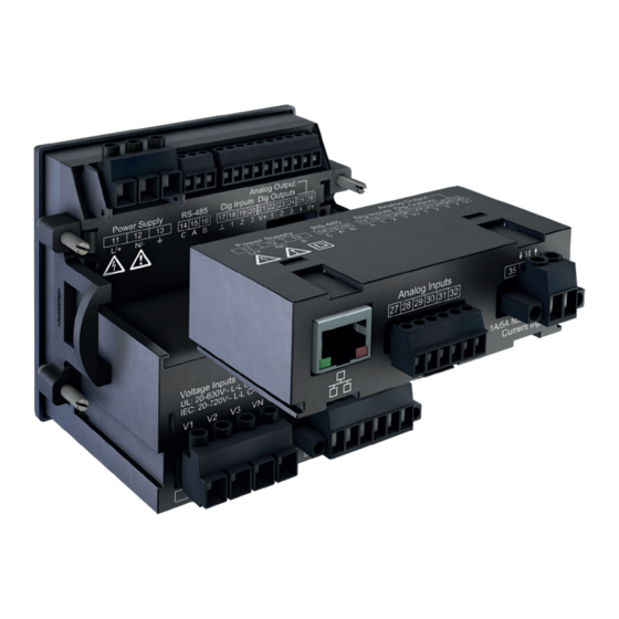
Fig.
UMG 96-PA with module 96-PA-RCM-EL
(with Ethernet interface)
Advertisement
Table of Contents

Related Manuals for janitza 96-PA-RCM


Summary of Contents for janitza 96-PA-RCM
- Page 1 Residual current expansion modules for the UMG 96-PA (from firmware 2.0) and UMG 96-PQ-L device series User manual Fig. UMG 96-PA with module 96-PA-RCM-EL (with Ethernet interface) Janitza electronics GmbH Vor dem Polstück 6 35633 Lahnau | Germany Support tel. +49 6441 9642-22...
- Page 2 Module 96-PA-RCM / 96-PA-RCM-EL www.janitza.de Module 96-PA-RCM and 96-PA-RCM-EL, RCM modules for extending the range of functions of the device series UMG 96-PA and UMG 96-PQ-L (from firmware 2.0) Doc. no.: 2.061.033.3.a Date: 02/2023 The German version is the original edition of the documentation...
- Page 3 Nonetheless, we wish to point out that updates of this document are not always possible at the same time as technical refinements are implemented in our products. Please see our website under www.janitza.de for the current version. Please see our website under www.janitza.de for the current version.
-
Page 4: Table Of Contents
Module 96-PA-RCM / 96-PA-RCM-EL www.janitza.de Table of contents 1. Information on the device and the user manual 1. 1 Disclaimer 1. 2 Copyright notice 1. 3 Technical changes 1. 4 About this user manual 1. 5 Defective device/disposal 2. Safety 2. - Page 5 6. 11 Connection example - DC power measurement 6. 12 Current measurement input I4 – neutral conductor measurement 6. 13 Temperature measurement input 6. 14 Ethernet interface (only module 96-PA-RCM-EL) 7. Operation and button functions of the basic device with module 7. 1 Operation 7.
- Page 6 Module 96-PA-RCM / 96-PA-RCM-EL www.janitza.de 8. Communication 8. 1 Basic device communication via the Ethernet interface (module 96-PA-RCM-EL) 8. 1. 1 Configuring Ethernet settings on the basic device 8. 1. 2 Configuring Ethernet settings via the GridVis software ® 8. 1. 3...
- Page 7 Module 96-PA-RCM / 96-PA-RCM-EL 13. Dismounting 14. Service and maintenance 14. 1 Repairs and calibration 14. 2 Service 14. 3 Device adjustment 14. 4 Calibration interval 14. 5 Firmware update 14. 6 Procedure in the event of a malfunction...
-
Page 8: Information On The Device And The User Manual
· Installation instructions · “GridVis Software” Quick Guide ® 1.2 Copyright notice · Safety information © 2023 - Janitza electronics GmbH - Lahnau. · GridVis online help ® All rights reserved. The device illustrations in this user manual show the UMG 96-PA as an example for the basic Any reproduction, processing, distribution or other device in some applications and functions. -
Page 9: Defective Device/Disposal
· When doing so, please bear the terms for trans- portation in mind. INFORMATION Please return defective or damaged devices to Janitza electronics GmbH in accordance with the shipping instructions for air or road freight (complete with accessories). Observe special regulations for devices with built-in... -
Page 10: Safety
Module 96-PA-RCM / 96-PA-RCM-EL www.janitza.de Safety The chapter on Safety contains information which 2.2 Hazard levels must be observed to ensure your personal safety Warning and safety information is marked by a and avoid material damage. warning symbol, and the hazard levels are shown as follows, depending on the degree of hazard: 2.1 Display of warning notices and safety... -
Page 11: Product Safety
Module 96-PA-RCM / 96-PA-RCM-EL 2.3 Product safety Therefore, when handling our devices, compo- nents, and modules, always observe the following: The device, the components and the modules · Do not exceed the limit values specified in the reflect current engineering practice and accepted user manual and on the rating plate;... -
Page 12: Electrically Qualified Personnel
Module 96-PA-RCM / 96-PA-RCM-EL www.janitza.de 2.5 Electrically qualified personnel 2.6 Warranty in the event of damage To avoid bodily injury and material damage, only Any unauthorized tampering with or use of the de- electrically qualified personnel are permitted to vice, component or module constitutes “misuse”... -
Page 13: Safety Information For Handling Current Transformers And Devices With Residual Current Measurement
Module 96-PA-RCM / 96-PA-RCM-EL 2.7 Safety information for handling current CAUTION transformers and devices with residual Risk of injury or damage to the device/your current measurement system due to short circuit! Inadequate insulation of the operating equipment WARNING at the residual current measurement input with... -
Page 14: Product Description
Module 96-PA-RCM / 96-PA-RCM-EL www.janitza.de Product description 3.1 Module description 3.3 Incoming goods inspection The RCM module enhances the scope of func- The prerequisites for trouble-free and safe op- tions of the basic device and is available in the eration of the modules include proper transport, following variants: storage, setup and assembly, as well as proper... -
Page 15: Intended Use
The modules 96-PA-RCM and 96-PA-RCM-EL Please see the EU/UK Declaration of Conformity · Are intended as plug-in modules for a basic posted at www.janitza.de for the laws, standards device (of the UMG 96-PA or UMG 96-PQ-L and directives applied by Janitza electronics device series) in switchboard cabinets and small GmbH for the devices. -
Page 16: Scope Of Delivery
· Procedure in the event of a malfunction, etc. can be found in the usage information of your basic device. A list of parameters and Modbus addresses with data on your basic device with module is avail- able for you as a download at www.janitza.de. -
Page 17: Gridvis Network Analysis Software
Module 96-PA-RCM / 96-PA-RCM-EL 3.9 GridVis network analysis software ATTENTION With the GridVis software, you have the perfect ® Material damage due to security vulnerabilities in programs, IT networks and protocols. tool for programming, reading out and visualizing Security vulnerabilities can lead to data misuse measurement data (download at www.janitza.de). -
Page 18: Mounting
Mounting 4.1 Mounting requirements for the basic device for use with module To be able to use the modules 96-PA-RCM and 96-PA-RCM-EL, the basic devices of the UMG 96- PA series require firmware from version 2.0 and hardware from version 4. -
Page 19: Module Mounting
Module 96-PA-RCM / 96-PA-RCM-EL 4.2 Module mounting Module-connector plug (rear of module) Module connector socket Fig. Module 96-PA-RCM-EL (with Ethernet interface) Mounting module: 1. Disconnect the system (basic device) from the power supply! 2. Remove the transport protection from the Fig. -
Page 20: Module Connections
Module 96-PA-RCM / 96-PA-RCM-EL www.janitza.de 4.3 Module connections Fig. Front view Fig. Rear view Module 96-PA-RCM-EL Module 96-PA-RCM-EL Item Designation Description Groove Guide groove for the mounting/dismantling of the module. Module connector Interface to basic device Only module 96-PA-RCM-EL: RJ45... -
Page 21: Module Markings - Rating Plates
Module 96-PA-RCM / 96-PA-RCM-EL 4.4 Module markings – Rating plates Module 96-PA-RCM Module 96-PA-RCM-EL Janitza electronics GmbH Janitza electronics GmbH Vor dem Polstück 6 Vor dem Polstück 6 35633 Lahnau / Germany 35633 Lahnau / Germany Modul 96-PA-RCM 01B • 1 Modul 96-PA-RCM-EL 01B •... -
Page 22: Installation
Fig. Rear side of basic device Ethernet Fig. example: Connection of the basic device via the Ethernet with connection interface of the 96-PA-RCM-EL module as a gateway between Module 96-PA-RCM-EL Modbus TCP and Modbus RTU INFORMATION The gateway acts as a Modbus TCP server and as a Modbus RTU client. -
Page 23: Connection To A Network
96-PA-RCM-EL on a network Fig. example: Basic device connected via the Ethernet interface of module 96-PA-RCM-EL to a network. 5.3 PC connection of the basic device with module via RS-485 interface (Modbus) Another method of connecting the basic device... -
Page 24: Connection Option With Terminal Assignment
Basic device 96-PA-RCM-EL Current measure- Supply voltage Voltage measurement Current measurement ment 11 12 13 PE/FE 230V/400V 50Hz Fig. Connection example “Basic device with module 96-PA-RCM-EL” Information on overcurrent devices can be found in the user manual of your basic device... -
Page 25: Inputs And Interfaces
Module 96-PA-RCM / 96-PA-RCM-EL Inputs and interfaces 6.1 Analog inputs I5 and I6 – Residual cur- The basic device with module measures residual rent input/current signal input currents according to IEC/TR 60755 (2008-01) of: Type A Type B and Type B+ (enhanced frequency... -
Page 26: Activate Cable Break Detection (Failure Monitoring) Rcm For I5 And I6
Module 96-PA-RCM / 96-PA-RCM-EL www.janitza.de 6.2 Activate cable break detection (failure monitoring) RCM for I5 and I6 The basic device with module has a “Cable break detection” feature (failure monitoring). With this feature, the basic device with module monitors the connection to the residual current transform- ers on the measuring inputs I5 and I6 (module mode Residual current - see chap. 9.2 on page... -
Page 27: Current Direction For The Current Transformer On I5 And I6
Module 96-PA-RCM / 96-PA-RCM-EL 6.3 Current direction for the current trans- 6.4 Residual current transformer example former on I5 and I6 A residual current transformer is used to mea- For residual current measurements at the measur- sure on insulated mains wiring in a 300 V CAT III ing inputs I5 and I6, the device makes no distinc- network. -
Page 28: Connection Example 1 - Residual Current Measurement
Module 96-PA-RCM / 96-PA-RCM-EL www.janitza.de 6.6 Connection example 1 - 6.7 Connection example 2 - Residual current measurement Residual current measurement Fig. Connection variant, residual current measurement via Fig. Connection variant, residual current measurement using a current transformer type A and type B. -
Page 29: Residual Current Limit Values
Module 96-PA-RCM / 96-PA-RCM-EL 6.9 Residual current limit values For setting and calculation of the residual current 2. “Calculation of the static residual current limit value, the basic device with module requires limit value” parameters which are set in the GridVis soft- ·... -
Page 30: Example Graph "Calculation Of The Static Residual Current Limit Value
Module 96-PA-RCM / 96-PA-RCM-EL www.janitza.de 6.9.2 Example graph “Calculation of the static residual current limit value” The example graph shows a static residual current limit value that applies for every nominal current value (of the system): · Nominal current reference value (not configurable). -
Page 31: Analog Inputs I5 And I6/U6 - Dc Power
Module 96-PA-RCM / 96-PA-RCM-EL 6.10 Analog inputs I5 and I6/U6 – DC power ATTENTION As an option for measuring the residual current, Damage to the device/your system due to short the basic device with module also permits use of... -
Page 32: Current Measurement Input I4 - Neutral Conductor Measurement
Module 96-PA-RCM / 96-PA-RCM-EL www.janitza.de 6.12 Current measurement input I4 – CAUTION neutral conductor measurement Risk of injury or damage to the device due to high measurement currents at the connections of the current transformers or the current mea- surement inputs of the device! High measurement currents can cause tempera- tures of up to 80 °C (176 °F) on the connections of... -
Page 33: Temperature Measurement Input
Module 96-PA-RCM / 96-PA-RCM-EL 6.13 Temperature measurement input Example of temperature sensor: A temperature sensor is used for measurement in the proximity of non-insulated mains wiring in a 300 V CAT III network. Solution: Use reinforced or double insulation for the tem- perature sensor for the 300 V CAT III network! This... -
Page 34: Ethernet Interface (Only Module 96-Pa-Rcm-El)
96-PA- found in chap. „8.1 Basic device communication via the Ethernet interface (module 96-PA-RCM-EL)“ RCM-EL via the Ethernet interface. on page 38. When connecting the Ethernet interface, ensure ·... -
Page 35: Operation And Button Functions Of The Basic Device With Module
Operation and button functions of the basic device with module 7.1 Operation 7.3 Measuring display Your basic device with module 96-PA-RCM or After a network recovery, the basic device with 96-PA-RCM-EL can be operated via 6 function module starts with the start screen (measured buttons for: value display Summary). -
Page 36: Overview Of The Additional Menu Items For Basic Devices With Module
Module 96-PA-RCM / 96-PA-RCM-EL www.janitza.de 7.5 Overview of the additional menu items for basic devices with module Menu Overview Residual current Voltage Overview Current Bar chart Current History, res. current 1 THD I History, res. current 2 History History L4... - Page 37 Module 96-PA-RCM / 96-PA-RCM-EL Configuration Language Communication Field bus Ethernet config. (-EL module only) Measurement Transformer Current transformer Voltage transformer L4 current transf. Nominal current Nominal frequency Module mode Residual current DC power Residual current Analog CH 1 type...
-
Page 38: Communication
Configuring Ethernet settings on the Ethernet interface (module 96-PA-RCM- basic device Configure the Ethernet settings or obtain details The basic device with module 96-PA-RCM-EL from the window Communication > Ethernet has six ways to allocate addresses for an Ethernet (TCP/IP): connection (TCP/IP): ·... -
Page 39: Configuring Ethernet Settings Via The Gridvis Software
Module 96-PA-RCM / 96-PA-RCM-EL 8.1.2 Configuring Ethernet settings via the 8.1.3 Configuring firewall settings via the GridVis software GridVis software ® ® In the GridVis software, you configure the Ether- With the firewall (from firmware 2.18), you can ®... -
Page 40: Basic Device Communication Via The Rs-485 Interface (Field Bus)
""/"" menu item Configuration and confirm with user interface as follows: button 6 Enter. 1. Basic device with module 96-PA-RCM: Menu Configuration > Communication 2. Basic device with module 96-PA-RCM-EL: Menu Configuration > Communication > Field- Fig. Configuration menu item 3. -
Page 41: Module-Relevant Alarms
Module 96-PA-RCM / 96-PA-RCM-EL 8.4 Module-relevant alarms ATTENTION When there is an alarm, the following warning alert A disconnected or defective module disrupts the communication with the basic device and appears: leads to a device fault. If communication between the basic device to... -
Page 42: Module-Relevant Configuration
Module 96-PA-RCM / 96-PA-RCM-EL www.janitza.de Module-relevant configuration Configure the relevant parameters for the module in the Measurement window of your basic device with module. To do so, use the function buttons 9.1 L4 current transformer (I4 - measure- of the basic device to go to the Measurement... -
Page 43: Module Mode
Module 96-PA-RCM / 96-PA-RCM-EL Residual current Settings parameters 9.2 Module mode Suitable transformer types: Analog CH 1 · AC (0 .. 30 mA type, The Module mode item in the Measurement win- · 0 .. 20 mA I5 terminal 29/30 · 4 .. 20 mA... - Page 44 Module 96-PA-RCM / 96-PA-RCM-EL www.janitza.de DC power measurement: Transformer ratio for the input I6/U6 20 mA 10 mA Fig. Window Display with the DC power parameters 0 mA 350 V 0 V 700 V DC power Voltage (primary) Settings parameters Fig. Graph “Transformer” analog input I6/U6...
-
Page 45: Temperature Sensor
(in scope of delivery). ® Fig. Configuration of the Modbus editor INFORMATION A Modbus address list for your basic device can be found in the download area at www.janitza.de. Recommendation: Use the GridVis power grid monitoring software ® for all module-relevant settings! -
Page 46: Module-Relevant Configuration With The Gridvis ® Software
Module 96-PA-RCM / 96-PA-RCM-EL www.janitza.de 9.5 Module-relevant configuration with the GridVis software ® The explanations of the measuring modes and the · Be sure to select the same measuring mode for settings can be found in section „9. Module-rele- L6 as for L5. - Page 47 Module 96-PA-RCM / 96-PA-RCM-EL DC power 0..20 / 4..20 mA measuring mode Fig. DC power measuring mode In the DC power measuring mode, the Current transformer menu shows the settings for L5; the Voltage transformer menu shows the settings for...
-
Page 48: Displays Of The Module
Module 96-PA-RCM / 96-PA-RCM-EL www.janitza.de 10. Displays of the module Opening a menu Press button 1 (Menu) to open the menu. Use buttons 3 () and 4 () to select the de- sired menu and confirm with button 6 (Enter). The module expands the menus with the displays shown below. -
Page 49: Residual Current Menu
Module 96-PA-RCM / 96-PA-RCM-EL 10.3 Residual current menu Overview Bar chart Residual current Summary Bargraph Linewriter RCM 1 Linewriter RCM 2 The menu is only available in the Residual current measuring mode. Measuring display for Current, Current Bar chart of the I-RCM1 and I-RCM2 mea- (max.), Limit value and Reference value of... -
Page 50: System Info Menu
Module 96-PA-RCM / 96-PA-RCM-EL www.janitza.de 10.5 System Info menu External temperature System info Com. RS485 Com. Ethernet Peripheral Ext. temperature Comparator groups Info base device Info module Bar chart and measuring display for the temperature (with min. and max. values) -
Page 51: Configuration Menu - Without Password/After Password Entry
Summary www.janitza.de Module 96-PA-RCM / 96-PA-RCM-EL Voltage Current Power Energy Consumption overview Drag Pointer 10.6 Configuration menu – without password/after password entry Harmonics Oszilloscope Events For information on the entries in the Configuration menu, see section„9. Mod- System info ule-relevant configuration“ on page 42. -
Page 52: Technical Data For The Module
Module 96-PA-RCM / 96-PA-RCM-EL www.janitza.de 11. Technical data for the module 11.1 Technical data General Net weight of module 78 g (0.17 lbs) (with attached plug-in connectors) Impact resistance IK07 according to IEC 62262 Transport and storage The following specifications apply for devices transported and stored in the original packaging. - Page 53 0.2 VA (Ri = 5 mΩ) Sampling frequency 8.33 kHz Resolution 16 bit Rated surge voltage 2.5 kV Overload for 1 s 60 A (sinusoidal) Ethernet interface (only module 96-PA-RCM-EL) Connection RJ45 Functions Modbus gateway Protocols ARP , IPv4, ICMP (ping) TCP , UDP Port: Application specific...
-
Page 54: Performance Characteristics Of Functions
Module 96-PA-RCM / 96-PA-RCM-EL www.janitza.de 11.2 Performance characteristics of functions Function Symbol Accuracy class Measuring range Display range Neutral conductor 1 (IEC61557-12) 0 .. 6 A 0 A .. 999 kA current I4, measured Neutral conductor 1.0 (IEC61557-12) 0.03 .. 25 A 0.03 A .. 999 kA... -
Page 55: Dimensional Drawings And Views
12. Dimensional drawings and views 12.1 Dimensional drawings · All specifications in mm (in). · The figures show the module 96-PA-RCM-EL and serve the purpose of illustration. · The views shown are not true to scale. Rear view (with connections) Side view 90.7 mm (3.57 in) - Page 56 Module 96-PA-RCM / 96-PA-RCM-EL www.janitza.de 13. Dismounting Dismounting module 96-PA-RCM or 96- Snap-in locking device PA-RCM-EL: 1. Disconnect the system (basic device) from the power supply! 2. Unlock your module by carefully lifting the snap-in locking device (fingernail or screw- driver if necessary) and pull it out of the slot.
- Page 57 Module 96-PA-RCM / 96-PA-RCM-EL 14. Service and maintenance Prior to outbound delivery, your device (compo- INFORMATION nent/module) is subjected to various safety tests This user manual describes the module and pro- and is marked with a seal. If the device (compo-...
- Page 58 Vor dem Polstück 6 | 35633 Lahnau Germany Tel: +49 6441 - 9642-0 info@janitza.de | www.janitza.de Doc. no. 2.061.033.3.a | Date 02/2023 | Subject to technical alterations. The current version of the document can be found in the download area at www.janitza.de.
Need help?
Do you have a question about the 96-PA-RCM and is the answer not in the manual?
Questions and answers