Table of Contents
Advertisement
Quick Links
Models 500 / 600
Commercial Condensing
Gas-Fired Water Boilers
Boiler Manual
WARNING
!
Installation and service of the boiler must be performed by a qualified installer or service technician.
Read all instructions, including this manual and all other information shipped with the boiler, before
installation or operation. Perform steps in the order given. Failure to comply can result in severe
personal injury, death, or substantial property damage.
Manual Part Number 550-100-273/0523
Advertisement
Table of Contents

Related Manuals for Weil-McLain SVF 500


Summary of Contents for Weil-McLain SVF 500
- Page 1 Models 500 / 600 Commercial Condensing Gas-Fired Water Boilers Boiler Manual WARNING Installation and service of the boiler must be performed by a qualified installer or service technician. Read all instructions, including this manual and all other information shipped with the boiler, before installation or operation.
- Page 2 Table of ConTenTs series boiler manual 500/600 Contents Abbreviations ..... . 4 Vent and Air Adapters Tools ......4 PVC Piping Venting and Combustion Air Options .
- Page 3 series boiler manual Table of ConTenTs 500/600 Check Natural or LP Gas Supply Pressure Gas Valve Adjustment Gas Train Diagram Maximum and Minimum Final Check Pipe Sizing for Natural Gas Check Ignition System Safety Shutoff Device Pipe Sizing for Propane Gas Check the System for Leaks Multiple Boiler Applications - Manifolded Gas Supply Lines Gas Valve Leakage Testing...
-
Page 4: Table Of Contents
Table of ConTenTs series boiler manual 500/600 Contents, continued SECTION 7 – PARTS SECTION 8 – SERVICE INFORMATION Miscellaneous Parts ....129 Ratings ......139 Ordering . - Page 5 series boiler manual safeTy 500/600 SeCTion 1 Safety Please Read Before Proceeding This section is intended to provide safety information WARNING Section Contents Adhere to all following guidelines and Safety Signals instructions in this section. Failure to adhere to Please Read Before Proceeding these guidelines can result in severe personal Safety Signals injury, death, or substantial property damage.
- Page 6 safeTy series boiler manual 500/600 Please Read Before Proceeding, continued Boiler Operation Freeze Protection Fluids • Do not block flow of combustion or ventilation air NEVER use automotive or standard glycol antifreeze, to boiler including glycol made for hydronic systems Use only •...
-
Page 7: Prepare Boiler Location
series boiler manual insTallaTion 500/600 SeCTion 2 Installation This section is intended to provide installation • For Canada only: Natural Gas and Propane instructions for qualified heating installers. Installation Code – CAN/CSA B149 1, and local codes • Where required by the authority having Section Contents jurisdiction, the installation must conform to the Standard for Controls and Safety Devices for... - Page 8 Minimum foundation dimensions The SVF Boiler is approved for installation on Boiler Model Minimum Dimensions (inches) combustible flooring, but must never be installed on SVF 500 29 x 44 x 2 carpeting SVF 600 29 x 44 x 2 WARNING...
- Page 9 series boiler manual insTallaTion 500/600 Clearances IMPORTANT Hot water pipes, vent pipes, and piping ends all have a minimum clearance requirement from combustible Without the recommended minimum clearances for surfaces There are also minimum allowable service service access, it may not be possible to service the clearances and recommended service access boiler without removing it from the space.
- Page 10 insTallaTion series boiler manual 500/600 Prepare Boiler Location, continued Air Openings SVF Boiler in a Room With Other Appliances: Follow the National Fuel Gas Code – ANSI Z223 1/ Direct Vent installations: Size openings only on NFPA 54, latest edition, for the U S Follow the the basis of the other appliances in the space No Natural Gas and Propane Installation Code –...
- Page 11 series boiler manual insTallaTion 500/600 Preparing for Multiple Boilers Provide the clearances shown in Figure 2 and Chalk-line boiler locations on foundation or boiler follow local codes Other layouts can be used if room floor. all required clearances are maintained Remove boilers from the crate and assemble Construct boiler foundation if the floor in the boiler according to instructions in this manual...
-
Page 12: Prepare The Boiler
insTallaTion series boiler manual 500/600 Prepare the Boiler Removing the Boiler from the Crate WARNING Leave the boiler in the crate pallet until ready to place The boiler is heavy. Use caution not to drop in the final location. Follow all uncrating instructions. the boiler. - Page 13 series boiler manual insTallaTion 500/600 Placing the Boiler Figure 4 Leveling legs warning Roll the boiler down the ramp and move the boiler into position The boiler must be unloaded from WARNING the pallet onto a solid, level surface WARNING LEVELING LEGS The boiler is heavy.
- Page 14 There is one orifice for properly between the blower and venturi Use the SVF 500/600 boiler. The orifice size is 0.494". a 13 mm wrench to secure the three nuts to Verify the orifice sizes on the venturi. The top the studs that hold the venturi to the blower orifice is 7.0 mm and the bottom orifice is 8.4 mm.
- Page 15 series boiler manual insTallaTion 500/600 High Altitude Installations Figure 7 Hydrostatic test piping connections - flanges, valves, and gaskets provided by installer For high altitude installations (over 2,000 ft ), Relief Valve Relief Valve maximum blower, minimum blower, and ignition RPM (installed after testing) (installed after testing) must be updated according to Table 18, page 115...
- Page 16 insTallaTion series boiler manual 500/600 Prepare the Boiler, continued Pressure Test Precautions WARNING DO NOT leave the boiler unattended at any Failure to comply with these precautions can time during testing. A cold water fill could result in severe personal injury, death, or expand and cause excessive pressure, substantial property damage.
-
Page 17: Install Water Piping
series boiler manual insTallaTion 500/600 Install Water Piping General Piping Information Figure 8 LWCO test button location NOTICE LWCO Test Button 230126 Use two wrenches when tightening water piping at the boiler with one at the boiler interior piping to prevent it from turning. - Page 18 insTallaTion series boiler manual 500/600 Install Water Piping, continued Relief Valve Installation Figure 9 Relief Valve Installed WARNING Do NOT install a relief valve with a pressure Relief Valve, higher than 160 psig. This is the maximum installed allowable relief valve setting for the SVF boiler. The boiler is shipped with a 30 psig relief valve.
- Page 19 Size system piping per Table 6, or apply recognized engineering practices to size the piping 10 PSI IMPORTANT The SVF 500 and 600 boilers have 2" NPT male connections. Installer to provide reducers to adapt 16** from external piping to the boiler supply and return SVF 600 connections if the system allows.
- Page 20 insTallaTion series boiler manual 500/600 Install Water Piping, continued Expansion Tank and Make-up Water Figure 11 Expansion tank piping - diaphragm-type tank Ensure the expansion tank size will handle boiler and system water volume and temperature See Table 26, From boiler/system To system page 139 for boiler water content The expansion tank must be located as shown in...
- Page 21 series boiler manual insTallaTion 500/600 ZONE VALVE Zoning - General The information on this page applies to all zone valve Controlling the circulators: zoning applications • The control can control up to five circulators. Refer to the Field Wiring section starting on page 64 for NOTICE instructions on wiring to circulators •...
- Page 22 insTallaTion series boiler manual 500/600 Install Water Piping, continued Figure 13 Zone valve zoning with optional DHW piping Additional ZONE VALVE Zoning - Primary/Secondary Zones ZONE 1 IMPORTANT Refer to page 21 for general zone valve zoning Do not exceed 8 pipe diameters information for all applications before installation.
- Page 23 series boiler manual insTallaTion 500/600 ZONE VALVE Zoning - Variable Primary Flow Figure 15 Variable primary flow, DHW as zone IMPORTANT Refer to page 21 for general zone valve zoning Additional information for all applications before installation. Zones ZONE 1 This configuration is for applications that use a variable flow system pump.
- Page 24 insTallaTion series boiler manual 500/600 Install Water Piping, continued Figure 17 Circulator zoning with optional DHW piping Additional ZONE VALVE Zoning - Circulator Zoning, Zones Primary/Secondary ZONE 1 IMPORTANT Do not exceed 8 pipe diameters Refer to page 21 for general zone valve zoning apart information for all applications before installation.
- Page 25 series boiler manual insTallaTion 500/600 ZONE VALVE Zoning - Water Chiller Figure 19 Chilled water system with optional DHW piping Systems, Primary/Secondary Additional Zones IMPORTANT ZONE 1 Refer to page 21 for general zone valve zoning information for all applications before installation. Do not exceed 8 pipe diameters apart...
-
Page 26: Commonwealth Of Massachusetts Installations
insTallaTion series boiler manual 500/600 Commonwealth of Massachusetts Installations Commonwealth of Massachusetts — When the boiler is installed within the Commonwealth of Massachusetts, the boiler must be installed by a licensed plumber or gas fitter. Read and comply with the instructions below. For all sidewall horizontally-vented gas- The following equipment is exempt from REQUIREMENTS:... -
Page 27: Venting And Combustion Air - General
series boiler manual insTallaTion 500/600 Venting and Combustion Air — General Code Compliance into the boiler room Follow the instructions in this manual and comply with all applicable codes Venting and combustion air piping installations Combustion air must not be exposed to any of the must provide provisions in accordance with “Air for contaminants listed in Table 7, page 28 Ensure Combustion and Ventilation,”... - Page 28 insTallaTion series boiler manual 500/600 Venting and Combustion Air — General, continued Using a Chimney Table 7 Corrosive contaminants and sources WARNING Products to avoid A chimney must only be used as a chase for vent Spray cans containing chloro/fluorocarbons and air piping and must meet all requirements Permanent wave solutions as listed below.
- Page 29 series boiler manual insTallaTion 500/600 Vent and Air Adapters Table 8 Vent and air adapter part numbers Vent connections are sized for DuraVent Fas-N- SVF Boiler Models 500/600 Seal , DuraVent PolyPro , PVC, and CPVC venting ® ® Mechanical Supplier / Vent Adapter Installers must provide the correct PVC/CPVC...
-
Page 30: Venting And Combustion Air Options
insTallaTion series boiler manual 500/600 Venting and Combustion Air Options Existing Vent System DANGER Turn on the clothes dryer and any other appliance DO NOT install the SVF boiler into a common not connected to the common venting system Turn vent with any other appliance. - Page 31 series boiler manual insTallaTion 500/600 Vent and Air Piping Materials WARNING Use only the materials listed in Table 9 for vent and air Failure to supply locking collars and seal the piping Ensure that all materials used meet local codes joints could cause vent and air piping leakage, See Table 8, page 29 for adapter part numbers which can result in severe personal injury, death,...
- Page 32 Scfm Inches W C flue temperature of 200°F, and it will shut down 500,000 -0 001 to -0 100 6" SVF 500 once it exceeds 210°F. The flue gas temperature 600,000 -0 001 to -0 100 6" SVF 600 standard is within 20°F and 30°F of the return water *The SVF boiler vent or air connection is sized for 4"...
- Page 33 series boiler manual insTallaTion 500/600 Category II Requirements, continued Code Compliance: WARNING Venting and combustion air piping installations must provide provisions for combustion and ventilation Install a Category II boiler system per all instructions in this manual. Improper Installation air in accordance with the section, “Venting of of a Category II vent system that results in Equipment"...
- Page 34 insTallaTion series boiler manual 500/600 Venting and Combustion Air Options, continued Vent and Air Terminations for Category IV The figure below lists the acceptable vent and air pipe terminations for Category IV as described in this manual. The SVF boiler vent or air connection is sized for 4" DuraVent Fas-N-Seal, DuraVent PolyPro, PVC, and CPVC The installer must provide the correct adapters/reducers needed to connect to other approved vent manufacturer's products The air inlet adapter is installed on the back of the boiler as shown in Figure 81, page 131...
-
Page 35: Room Air Openings
series boiler manual insTallaTion 500/600 Room Air Openings Combustion Air Provision — Direct Exhaust The SVF commercial boiler is rated Category IV and has varying requirements for combustion The SVF commercial boiler can use inside air if and ventilation air, reflected by the special sizing no contaminants are present in the boiler space instructions given in this manual Refer to the National If contaminants are likely to be present, install the... - Page 36 insTallaTion series boiler manual 500/600 Room Air Openings, continued Figure 23 Minimum combustion air openings for DIRECT EXHAUST applications Air openings SVF boiler WITH other appliances in SVF boiler WITHOUT other The required air opening sizes below are FREE the same room appliances in the same room AREA, after reduction for louver obstruction See the important below for large spaces...
- Page 37 series boiler manual insTallaTion 500/600 Figure 24 Minimum combustion air openings for DIRECT VENT applications Air openings SVF boiler WITH other appliances in SVF boiler WITHOUT other The required air opening sizes below are FREE the same room appliances in the same room AREA, after reduction for louver obstruction See the important below for large spaces 0 to 12"...
- Page 38 insTallaTion series boiler manual 500/600 Room Air Openings, continued Combustion Air Manifold Option – Category IV Figure 25 Manifolded combustion air option - DIRECT Only VENT only Multiple Category IV SVF boilers can use a common combustion air manifold Size the duct to provide at least one square inch per 2,000 Btuh total input of Minimum 3 feet below any vent termination within 10 feet connected boilers Provide a minimum clearance to...
-
Page 39: Direct Exhaust - Vertical Termination (Cat Ii And Iv)
series boiler manual insTallaTion 500/600 DIRECT EXHAUST — Vertical Termination (Cat. II and IV) Vertical Termination Location Figure 26 Vertical direct exhaust termination The vent termination must be installed as shown in Figure 26 The termination placement must comply B i r d B i r d with clearances and limitations shown in Figure 27, s c r e e... - Page 40 insTallaTion series boiler manual 500/600 DIRECT EXHAUST — Vertical Termination (Cat. II and IV), continued Vent Piping Installation Vent Termination Installation WARNING Vent pipe penetration: Use only the vent materials and kits listed in a Cut a hole for the vent pipe Table 9, page 31.
-
Page 41: Direct Exhaust - Sidewall Termination (Category Iv)
series boiler manual insTallaTion 500/600 DIRECT EXHAUST — Sidewall Termination (Category IV) Sidewall Termination Location WARNING • Vent and air terminations must be installed at least Follow all location requirements in this section. 12" (0 31m) above grade and snow line Failure to comply can result in severe personal •... - Page 42 insTallaTion series boiler manual 500/600 DIRECT EXHAUST — Sidewall Termination (Category IV), continued Determine Termination Location Figure 28 Sidewall direct exhaust termination The vent termination must be installed as shown in Figure 28 and Figure 30, page 43 The termination B i r d B i r d placement must comply with clearances and...
- Page 43 series boiler manual insTallaTion 500/600 Vent Termination Installation Figure 29 Multiple boiler direct exhaust sidewall terminations Maintain the required dimensions of the finished B i r d B i r d termination piping as shown in Figure 27, page 41 V e n t V e n t s c r e e...
-
Page 44: Direct Vent - Vertical Termination (Category Iv)
insTallaTion series boiler manual 500/600 DIRECT VENT — Vertical Termination (Category IV) Vertical Termination Location Figure 31 Vertical direct vent terminations The vent and air terminations must be installed V E N T V E N T as shown in Figure 31 The air termination can be through either the roof or a sidewall as shown The termination placement must comply with clearances A I R... - Page 45 series boiler manual insTallaTion 500/600 Vent and Air Termination Installation Figure 32 Vertical vent & air terminations B I R D B I R D Maintain the required dimensions of the finished S C R E S C R E termination piping as shown in the figures in this section 1 2 ”...
- Page 46 insTallaTion series boiler manual 500/600 DIRECT VENT — Vertical Termination (Category IV), continued Vent and Air Termination Installation, cont. Figure 34 Vertical vent with sidewall air - termination locations Vertical vent termination with sidewall air B i r d B i r d termination as shown in Figure 34: s c r e e s c r e e...
-
Page 47: Direct Vent - Sidewall Separate Pipes (Category Iv)
series boiler manual insTallaTion 500/600 DIRECT VENT — Sidewall Separate Pipes (Category IV) Sidewall Termination Location WARNING • Vent and air terminations must be installed at Follow all location requirements in this section. least 12" (0 31m) above grade and snow line Failure to comply can result in severe personal •... - Page 48 insTallaTion series boiler manual 500/600 DIRECT VENT — Sidewall Separate Pipes (Category IV), continued Determine Termination Location Figure 37 Sidewall direct vent terminations – separate pipes The vent termination must be installed as shown in Air elbow Figure 37 and Figure 39, page 49 The termination snorkel option placement must comply with clearances and limitations shown in Figure 36, page 47...
- Page 49 series boiler manual insTallaTion 500/600 Vent Piping Installation Figure 39 Sidewall assembly, separate pipes – direct vent WARNING Use only the vent materials and kits listed in Table 9, page 31. Failure to comply can result in severe personal injury, death, or substantial property damage.
-
Page 50: Direct Vent - Vertical Concentric (Category Iv)
insTallaTion series boiler manual 500/600 DIRECT VENT — Vertical Concentric (Category IV) Determine Termination Location Figure 40 Concentric vertical installation The concentric termination kit must be purchased separately (see page 129) The concentric vent and air inlet assembly must terminate as shown in Figure 42, page 51 The termination must comply with clearances and limitations shown in Figure 36, page 47 WARNING... - Page 51 series boiler manual insTallaTion 500/600 Concentric Piping Termination Installation, cont. Figure 41 Concentric vertical termination – single or multiple boilers 1 2 i n . 1 2 i n . Support the concentric vent/air termination at the m i n . m i n .
-
Page 52: Concentric Termination, Typical
insTallaTion series boiler manual 500/600 Concentric Termination, Typical Assembling Concentric Terminations Figure 43 Concentric termination assembly Follow all instructions provided with the concentric termination kit The following are general guidelines for information only The typical assembly of a concentric termination assembly is shown in Figure 43 See the kit instructions for details of polypropylene kits WARNING... -
Page 53: Direct Vent - Sidewall Concentric (Category Iv)
series boiler manual insTallaTion 500/600 DIRECT VENT — Sidewall Concentric (Category IV) Determine Termination Location Figure 44 Sidewall direct vent terminations – concentric The concentric termination kit (purchased separately) must be installed as shown in Figure 44 and Figure 46, page 54 The termination placement must comply with clearances and limitations shown in Figure 36, page 47 p i c a l... - Page 54 insTallaTion series boiler manual 500/600 DIRECT VENT — Sidewall Concentric (Category IV), continued Concentric Piping Termination Installation Figure 46 Concentric sidewall vent assembly supports WARNING Use only the vent materials and kits listed in Table 9, page 31. Failure to comply can result in severe personal injury, death, or substantial property damage.
- Page 55 series boiler manual insTallaTion 500/600 Concentric Piping Termination Installation, cont. Vent Piping Installation WARNING The supports and bracing used must support the termination assembly to prevent slippage or Every joint on polypropylene vent piping must movement See instructions provided with the include a locking collar.
-
Page 56: Direct Vent - Sidewall Vent And Air Plate (Category Iv)
insTallaTion series boiler manual 500/600 DIRECT VENT — Sidewall Vent and Air Plate (Category IV) Determine Termination Location Figure 47 Sidewall direct vent terminations – vent and air plate The vent and air plates must be installed as shown in Figure 50, page 58 The termination placement must comply with clearances and limitations shown in Figure 36, page 47 To boiler... - Page 57 Figure 49 Wall hole preparation (inside view) – use provided template WARNING For the Weil-McLain plate, the template must be Minimum vent pipe hole: Drill: 3-1/2" diam for 3" air pipe level to ensure the flue and air pipe will be side- Combustible materials: Drill: 4"...
- Page 58 insTallaTion series boiler manual 500/600 DIRECT VENT — Sidewall Vent and Air Plate (Category IV), continued Vent and Air Plate Installation, continued Figure 50 Plate termination assembly (inside view) Test fit the vent/air termination on the vent pipe. Make sure the vent pipe fully penetrates the termination socket and the air pipe butts against the interior stops Apply silicon RTV sealant to the interior of the...
-
Page 59: Install Condensate Components
Provide an external power source for the pump Minimum recommended condensate pump capacity in gallons per hour per boiler: • SVF 500, 10 GPH • SVF 600, 10 GPH When sizing condensate pumps, make sure to include the total load of all SVF boilers connected... -
Page 60: Gas Piping
insTallaTion series boiler manual 500/600 Gas Piping Gas Supply Piping Connection Figure 53 Gas supply piping connection (fittings and gas valve supplied by installer) WARNING From gas From gas supply supply Use two wrenches when tightening gas piping at the boiler. Use one wrench to prevent the boiler gas line connection from turning. - Page 61 series boiler manual insTallaTion 500/600 Check Natural or LP Gas Supply Pressure Figure 54 Gas line tapping Purge all air from the gas supply piping Check the boiler and its gas connection for leaks before placing the boiler in operation a Close manual main shut-off valve during any pressure testing at less than 14"...
- Page 62 insTallaTion series boiler manual 500/600 Gas Piping, continued Pipe Sizing for Natural Gas Table 11 Pipe capacity for natural gas Size gas supply piping from meter outlet to the Gas Supply Pipe Capacity (cubic feet per entrance of the boiler in accordances with Table Gas Pipe hour) @ 0.30"...
- Page 63 Power Requirements external devices that are not listed in this manual. The installation must comply with the National • The SVF 500/600 boilers are manufactured for Electrical Code and any other national, state, 120 Vac, 60 Hz electrical service provincial, or local codes and regulations In Canada, •...
- Page 64 eleCTriCal series boiler manual 500/600 Field Wiring Terminal Connections Line voltage – three knockouts on the left of the cabinet, and three knockouts on the back (Line All low voltage field wiring is made directly to the In, Outputs 1, 2, 3, 4) corresponding terminal blocks on the circuit board Low voltage –...
- Page 65 series boiler manual eleCTriCal 500/600 Figure 57 Boiler back knockouts Figure 56 Boiler front knockouts Back Back Front Front Knockouts Knockouts Knockouts Knockouts 230027 230026 550-100-273/0523...
- Page 66 500/600 Field Wiring, continued Schematic Diagram Figure 58 Schematic wiring diagram for SVF 500/600 boilers (continued on the next page) 500/600 Spark valve Field wiring electrode J6-9 Schematic Wiring Diagram Factory wiring (See ladder wiring diagram for notes)
- Page 67 Air Temp. switch 5VDC External if used if used Temp. Temp. Sensor Ground Weil-McLain • 500 Blaine St. • Michigan City, IN 46360-2388 Flue Pressure (Will require (Control (If Used) (If Used) (if used) LWCO manual Reset) will auto- switch...
- Page 68 500/600 Field Wiring, continued Ladder Diagram Figure 59 Ladder wiring diagram for SVF 500/600 boilers (continued on the next page) Blower Relay 550-100-273/0523...
- Page 69 Legend for ladder wiring diagram only 120VAC field wiring Low voltage field wiring Field ground connectors 120VAC factory wiring Low voltage factory wiring High voltage spark ignition wiring Ground connectors Weil-McLain • 500 Blaine St. • Michigan City, IN 46360-2388 Part Number 550201629/0523 550-100-273/0523...
- Page 70 eleCTriCal series boiler manual 500/600 Field Wiring, continued Terminal Block Wiring A. 120 Vac Power Supply — REQUIRED Terminal Strip T1 1 Provide and install a properly-sized, fused Determine Total Load disconnect or service switch as required by applicable codes Boiler amps 2 Use the table at the right to determine the total load...
- Page 71 series boiler manual eleCTriCal 500/600 C. Inputs 1, 2, 3, and 4 – As needed for systems Connector J17 (Inputs 1, 2, and 3) and Connector J16 (Input 4, 0-10 Vdc Input, 0-10 Vdc Output) • Input 1: Connector J17 – 1, 2 & 3 (common) TT or end switch inputs •...
- Page 72 eleCTriCal series boiler manual 500/600 Field Wiring, continued Terminal Block Wiring, continued E. Outdoor Temperature (ODT) Sensor – Optional Connector J19 1 The control provides programmable options if using an ODT sensor This sensor is supplied with the boiler 2 Mount the ODT sensor on an exterior wall, shielded from direct sunlight and flow of heat or cooling from other sources 3 The wire outlet on the sensor must be oriented DOWN to prevent water entry 4 Connect the sensor leads to the terminal shown at right and in Figure 58,...
- Page 73 series boiler manual eleCTriCal 500/600 G. Low Water Cut-off (LWCO) – Discrete and Integrated Connectors J9 and J21 1 An LWCO is integrated in the Boiler Out sensor and connects to J9 See image at right and page 17 Pin 4 2 Other LWCOs can be used with the SVF only if the device uses an isolated Boiler outlet contact for the LWCO function Connect as shown at bottom right...
- Page 74 eleCTriCal series boiler manual 500/600 Field Wiring, continued Terminal Block Wiring, continued J. Closure Switch – Recommended Jumper on Connector J18 IMPORTANT The devices used must provide electrically isolated contacts because the J18 jumper circuit carries 5 Vdc. 1 A flow switch or combustion air damper (CAD) interlock can be configured by 2 3 3 removing the jumper on connector J18 and wiring components as shown 2 No control settings are required when using a flow switch.
- Page 75 series boiler manual eleCTriCal 500/600 L. 0-10 Vdc Remote Modulation Input – Optional Connector J16 #5 and #6 IMPORTANT The control can be configured to use either 0–10 Vdc for target operation (see previous section) or modulation, but not both. 1 The illustration on the right shows how to connect TT or end switch contacts at TT or end switch inputs INPUT 3 and INPUT 4 for other uses...
- Page 76 eleCTriCal series boiler manual 500/600 Field Wiring, continued Terminal Block Wiring, continued M. 0-10 Vdc Output Connector J16 #7 and #8 1 Control setup – lead/lag: a 0–10 Vdc Output functionality allows classic lead/lag system operation, and allows for cooperation with other heat sources that utilize 0-10 Vdc inputs as a source b Connect on either Master or Shadow and assign Local 1/Local 2 to use Additional Heat Demand (AHD) For single boiler, connect on any input and...
- Page 77 series boiler manual eleCTriCal 500/600 N. Multiple Boiler and the Modbus Connection Connector J12 1 The boiler control is capable of multiple boiler communication and can control up to eight Unity™ 1 0 and 2 0 boilers in one installation 2 To activate the Modbus communications, navigate to the Contractor menu by holding the WM logo, then press the <MODBUS SETTINGS>...
- Page 78 eleCTriCal series boiler manual 500/600 Zoning with the Control A. Zoning with Circulators – Suggested Applications Four space heating zones (no Indirect DHW) • Review wiring information in Section B on page 70 and Section C on page 71 Circulators (2 2 amps max) or Zone thermostats •...
- Page 79 series boiler manual eleCTriCal 500/600 B. Zoning with Zone Valves – Suggested Applications Connector J16 #5 and #6 WARNING The system must be equipped with a by-pass Zone Valves (120 Vac) System Circulator pressure regulating valve. Flow can occur with 2.2A Max.
- Page 80 eleCTriCal series boiler manual 500/600 This page intentionally left blank 550-100-273/0523...
- Page 81 series boiler manual operaTion 500/600 SeCTion 4 Operation Control Setup This section is intended to provide instructions for control setup and boiler startup procedures Set control parameters using the Wizard Section Contents option provided on initial start-up, or manually enter parameters using control menus See Control Setup and Operation the Advanced Manual (550-100-207) and the Startup —...
- Page 82 operaTion series boiler manual 500/600 Control Setup and Operation, continued Control Features Table 13 Control sequence of operation ‰ Upload, adjust settings, and perform easier Display diagnostics via wireless communication Control action status ‰ Color touch-screen display for ease of operation (Also see the Advanced Manual) text monitoring and troubleshooting...
- Page 83 series boiler manual operaTion 500/600 Sequence of Operation Table 14 Steps for boiler setup A summary of the control sequence is shown in Table Setting Up the Boiler 13, page 82 The statuses shown appear in the Determine input/output needs – display as the control cycles the boiler See Figure What are the inputs? –...
- Page 84 operaTion series boiler manual 500/600 Control Setup and Operation, continued Control Operation Figure 60 Outdoor reset operation The control responds to signals from: a Room thermostats MAX TARGET TEMP = 180 MAX TARGET TEMP = 180 b DHW aquastats (if used) c Temperature sensors Boiler Out, Boiler In, MAX TARGET TEMP = 160 MAX TARGET TEMP...
- Page 85 series boiler manual operaTion 500/600 Remote Target Operation Figure 61 Remote target operation (0–10 Vdc input) This function allows a remote analog input to MAX TARGET TEMP = 180 MAX TARGET TEMP = 180 regulate the supply temperature for control VOLTAGE FOR MAX TARGET = 7 VOLTAGE FOR MAX TARGET = 7 operation/modulation This can be done for any...
- Page 86 Occurs when a new control is first powered, or when a control is reset to factory defaults; this will not VERSION 66.00 be shown on new boilers as the control has been factory tested SVF 500/600 CONTRACTOR MENU CONTRACTOR MENU STARTUP SCREEN BOILER MODEL...
- Page 87 S S p p a a c c e e h h e e a a t t i i n n g g S S t t a a n n d d b b y y SVF 500/600 SVF 500/600 ®...
- Page 88 For more information and settings see the Advanced menu navigation for boiler connectivity Manual (part number 550-100-207) Figure 65 NAVIGATION menus Menu Item Purpose SVF 500 • Banner info ° • Status image • Fault name and reset button • Time/Date HOME SCREEN •...
- Page 89 Select <RESET REMINDER> to reset for the next for seven seconds from the Home screen See the maintenance date Advanced Manual for more settings and information Figure 66 CONTRACTOR menus SVF 500 Menu Item Purpose ° • Set or change boiler model, control...
- Page 90 Softened water must NOT be used without b See the Parts section starting on page 129 for Sentinel X100 as boiler corrosion may occur Weil-McLain part numbers to obtain cleaning Hardness must be less than 7 grains agents through a WM Technologies distributor...
- Page 91 Calculate the total volume (gallons) of all system McLain distributor Other approved antifreezes are piping and components, including the expansion listed on weil-mclain com tank and boiler Boiler water content is listed in Read all warnings above before using any freeze Table 26, page 139...
- Page 92 Add additional inhibitor if necessary annually The pH of the water mixture must be See manufacturer instructions or www weil-mclain between 7 0 and 8 5 Alternately, use the Sentinel to determine how much inhibitor to use inhibitor test kit to check concentration...
- Page 93 series boiler manual operaTion 500/600 Startup — Final Checks Check for Gas Leaks Figure 68 Test port cap removal Before starting the boiler, and during initial operation, use a leak detector or smell around the boiler and floor for gas odorant or any unusual odor. Remove the boiler jacket door and smell the interior of the boiler jacket WARNING...
- Page 94 operaTion series boiler manual 500/600 Startup — Final Checks, continued Inspect the Pressure Switch Hose Figure 69 Pressure switch tube locations Inspect the pressure switch sense hose and verify 3.25" Flue Switch correct installation See Figure 69 Replace the hose Above control on the left if necessary NOTICE...
- Page 95 series boiler manual operaTion 500/600 Figure 70 Operating instructions, warning FOR YOUR SAFETY READ BEFORE OPERATING If you do not follow these instructions exactly, a fire or explosion may result causing property damage, personal injury or loss of life. A. This appliance does not have a pilot. It is C.
- Page 96 operaTion series boiler manual 500/600 Startup Procedure Starting the Boiler Table 16 Acceptable combustion values Apply power to the boiler via the service switch High Fire Low Fire Fuel Follow the operating instructions on page 95 % CO CO ppm % CO CO ppm If this is the first time powering the boiler, refer to...
- Page 97 series boiler manual operaTion 500/600 Check Flame and Combustion, continued Figure 71 Throttle and offset regulating screws Low Fire Check: Offset Adjustment Offset Adjustment 10 In Manual Test Mode, and with FORCE RATE highlighted, select <EDIT> Using the up and down arrows, select <LOW>...
- Page 98 operaTion series boiler manual 500/600 Startup Procedure, continued Gas Valve Adjustment, continued Maximum and Minimum Final Check High fire adjustment: Turn the boiler off, then restart it and put into test mode at high fire. Ensure the CO setting level IMPORTANT has remained unchanged, and confirm that CO is Adjust only the throttle screw for high fire.
- Page 99 series boiler manual operaTion 500/600 Check the System for Leaks, continued Figure 72 Ignition sequence timing Inspect the joints between the condensate dish, IGNITION SEQUENCE TIMING vent adapter, and vent pipe BLOWER Check for gas-tight seals at every connection and seam of air and vent piping GAS VALVE A leak appears as vapor on the surface of the...
- Page 100 operaTion series boiler manual 500/600 Startup Procedure, continued Verification Check List ‰ Verified that the control is programmed correctly? ‰ For multiple zones, adjusted for correct flow in ‰ Verified that the boiler and heat distribution units each zone? are filled with water? ‰...
- Page 101 series boiler manual mainTenanCe 500/600 SeCTion 5 Maintenance Preventative measures include the following: This section is intended to provide maintenance instructions and timing for the boiler • Avoid breathing in dust • Wear long-sleeved, loose fitting clothing, gloves, Section Contents and eye protection •...
- Page 102 mainTenanCe series boiler manual 500/600 Annual Inspection First-Year Special Inspection Obtain a Boiler Annual Maintenance Kit (part number d Make sure there is no blockage or accumulation 384-000-422) before attempting the first-year of debris in the burner or burner ports Replace inspection to ensure all needed parts are available the burner if necessary This kit includes a heat exchanger cover plate...
- Page 103 series boiler manual mainTenanCe 500/600 General Inspection Information WARNING The boiler should be inspected and started at the Jacket door gaskets must be intact and must beginning of the heating season annually, only by a provide a reliable seal. Failure to comply can qualified service technician.
- Page 104 mainTenanCe series boiler manual 500/600 Annual Inspection, continued Service and Maintenance Schedules Service Technician Owner Maintenance (use this manual for instructions) (see the User Manual for instructions) General: ‰ Check the boiler area ‰ Investigate reported issues ‰ Check air openings ‰...
- Page 105 series boiler manual mainTenanCe 500/600 Annual Startup Check Air Openings b Make sure the vents do not leak c Replace any leaking vents Verify that combustion and ventilation air Check the system water chemistry See page 90 openings to the boiler room and building are open Check the Boiler Relief Valve and unobstructed Check operation and wiring of automatic...
- Page 106 mainTenanCe series boiler manual 500/600 Annual Startup, continued Check the Expansion Tank Diaphragm- or bladder-type: Welded gas tight with a rubber membrane to separate the tank pressurizing Expansion tanks provide space for water to move air and the water This tank may be located at any in and out as the heating system water expands or point in the system, but it is most often found near the contracts due to temperature increases or decreases...
- Page 107 series boiler manual mainTenanCe 500/600 Inspect the Ignition Electrode and Wiring Figure 73 Boiler interior assembled view See the figures to the right for the references below. Shut off power to the boiler. Close the external manual gas valve to ensure there is no gas flow to the unit.
- Page 108 mainTenanCe series boiler manual 500/600 Annual Startup, continued Inspect and Clean the Burner Inspect the burner exterior It must be in good condition with no visible damage WARNING Clean the underside of the burner flange with The boiler contains ceramic fiber materials. a soft brush to remove any remaining gasket Use care when handling these materials per fragments...
- Page 109 series boiler manual mainTenanCe 500/600 Cleaning the Heat Exchanger - Water Side In order for the efficiency of boilers to increase Disconnect the blower from the cover plate with a beyond the condensing limit, new materials have 13 mm wrench or socket Carefully lift the blower, been introduced for the heat exchanger, including venturi, and gas valve assembly out of the boiler stainless steel Stainless steel has excellent heat...
- Page 110 mainTenanCe series boiler manual 500/600 Annual Startup, continued Reinstalling All Components Figure 75 Cover plate and gasket installation See the figures on page 107, Figure 75, and Figure 76, page 111 for the references below Place the cover plate onto the heat exchanger Ensure the blower flange is facing the front of the boiler and square Install all bolts finger-tight from the heat...
- Page 111 series boiler manual mainTenanCe 500/600 Figure 76 Cover plate nut tightening sequences • Gradually tighten the cover plate and burner plate access bolts in the sequence shown in the illustration • Burner torque: 70 in-lbs (7 90 Nm), 10 mm wrench •...
- Page 112 mainTenanCe series boiler manual 500/600 Annual Startup, continued Inspecting the High Flue Pressure Switch Figure 77 Pressure switch connection Ensure the wire connects on the pressure switch are properly connected and the tubes are secured to the pressure ports Inspect the tubes for any signs of damage or debris Replace if necessary After checking the control settings, disconnect the tube connection with the condensate dish...
- Page 113 500/600 Check the Burner Flame Table 17 Flame signal values WARNING Flame Signal Values for SVF 500/600 Boilers The boiler contains ceramic fiber materials. Gas Type Boost Shutdown Proof of Flame Use care when handling these materials per Natural Gas instructions on page 101.
- Page 114 mainTenanCe series boiler manual 500/600 Annual Startup, continued Check the Flue Gas Temperature High Altitude Set the boiler to high fire. The boiler will automatically derate the BTU values Adjust the control display to view flue gas listed in Table 18, page 115 at altitudes over temperature and boiler return temperature 2,000 ft above sea level The flue gas temperature should be no more than...
- Page 115 series boiler manual mainTenanCe 500/600 Table 18 Natural gas (NG) and propane (LP) firing rates and corresponding blower speeds (low fire and high fire), for altitudes up to 2,000 ft (default settings), and for high altitudes (above 2,000 ft ) Low Fire Model and 500 NG...
- Page 116 mainTenanCe series boiler manual 500/600 Annual Startup, continued Manual Test Mode The selected boiler will run at the forced rate until it is either returned to AUTO, or until 30 minutes of Single Boiler: inactivity on the master control To return the rate to AUTO, select <END MANUAL TEST>...
- Page 117 series boiler manual TroubleshooTing 500/600 SeCTion 6 Troubleshooting Diagnosing Boiler Issues This section is intended to provide solutions by troubleshooting various issues with the boiler See Checking the Boiler the SVF Advanced Manual for complete information Section Contents Check the following items first when servicing the boiler Troubleshooting —...
- Page 118 TroubleshooTing series boiler manual 500/600 Diagnosing Boiler Issues, continued Checking the Control Fuses Turn off power to the boiler at the external line switch WARNING Remove the control access door Do not jumper fuses or replace with any fuse Remove and inspect the seven fuses (Items 1, except as specified.
- Page 119 series boiler manual TroubleshooTing 500/600 Checking the In-Line Fuses Figure 79 In-line fuses Turn off power to the boiler at the external line switch Remove the control access door Remove control tray panel to reach blower in- line fuse holders Two holders are present in this Closed boiler Carefully twist the top of the blower fuse holder...
- Page 120 TroubleshooTing series boiler manual 500/600 Errors and Lockouts Control Fault Indications Resetting the Control WARNING The control settings can be reset by either resetting Make sure to determine the causes of outages. the Wizard and inputing new information, or resetting Do not leave the boiler operating without a all control settings to factory default settings complete diagnosis.
- Page 121 TroubleshooTing 500/600 Figure 80 Control display when in lockout SVF 500 LOW WATER CUTOFF ° R R E E S S E E T T 5/01/20 9:24 AM LOW WATER CUTOFF MAINTENANCE PUMPS/AUX : 1234 BOILER NAME :...
- Page 122 TroubleshooTing series boiler manual 500/600 Errors and Lockouts, continued Fault and Action Items Table 21 Control fault information and troubleshooting (continued on the following pages) Fault Condition Troubleshooting Action Nothing is shown on the Control is not receiving 24V Check wiring for short circuit or incorrect Correct wiring per wiring diagram including display screen, and the power...
- Page 123 series boiler manual TroubleshooTing 500/600 Fault Condition Troubleshooting Action Outdoor Outdoor temperature sensor Will automatically reset if • Determine which sensors are suspect and measure their resistance Sensor Error is short or open the condition clears value and compare it to the values shown in Table 19, page 119 If the resistance values are incorrect, replace the temperature sensor Refer Warning only: Max to the Parts section, starting on page 129, for the proper part number...
- Page 124 TroubleshooTing series boiler manual 500/600 Errors and Lockouts, continued Fault and Action Items, continued Fault Condition Troubleshooting Action Clock Fault When the real time clock When the real time clock chip is working • Enter an updated time/date chip cannot be read correctly and has had a time written to it •...
- Page 125 series boiler manual TroubleshooTing 500/600 Fault Condition Troubleshooting Action FLAME Flame value dropped Automatically resets after • Check condensate trap for blockage allowing condensate to accumulate LOSS below the allowable one hour or can be reset by inside heat exchanger FAULT Proof of Flame performing manual reset on...
- Page 126 TroubleshooTing series boiler manual 500/600 Errors and Lockouts, continued Fault and Action Items, continued Fault Condition Troubleshooting Action HIGH TEMP Boiler temperature Reset using manual reset Verify that high limit setting is at least 10° F above the maximum target LIMIT sensor reached High screen on display...
- Page 127 series boiler manual TroubleshooTing 500/600 Fault Condition Troubleshooting Action Internal Clock Occurs when the Clears when the control • Cycle power of the boiler Fault internal clock of the sees a valid clock count • Check the wiring of the display control is out of sync within the control •...
- Page 128 TroubleshooTing series boiler manual 500/600 Errors and Lockouts, continued Fault and Action Items, continued Fault Condition Troubleshooting Action Software Main control and display Unit is updated to matching software Check software versions for main control and display Incompatible software are not compatible Replace the hardware that is the incorrect software version Supply 60F >...
-
Page 129: Miscellaneous Parts
Bird Screens (2 required) — for 4" PVC vent and air pipes 383500110 Kit – Service Annual Maintenance Kit SVF 500/600: (electrode ignitor, insulation, gaskets, fasteners) 384000422 Conversion Kit, Natural Gas to LP SVF 500/600 (venturi, venturi gasket, O-ring, LP orifice, hardware, instructions) 384000423 Kit – Service Automatic Air Valve 384000153... -
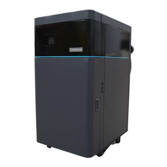
Page 130: The Svf Commercial Condensing Water Boiler
parTs series boiler manual 500/600 The SVF Commercial Condensing Water Boiler Legend for Figure 81, page 131 1. Stainless steel heat exchanger 19. Water return pipe (system return) 72 91 square ft of surface for heat transfer SA-240 stainless steel, 2"... - Page 131 series boiler manual parTs 500/600 Figure 81 The SVF commercial condensing water boiler Electrical Panel Components Components - Top View Components - Back View Components - Front View 230114 550-100-273/0523...
-
Page 132: Replacement Parts
Kit – Service Control Cover 384000338 Kit – Service Bracket, External Transformer 384000339 Kit – Service Panel, Flue Adapter, Top SVF 500/600 384000404 Kit – Service Panel, Flue Adapter, Bottom SVF 500/600 384000405 Kit – Service Gaskets, Door (not shown) 384000361 Kit –... - Page 133 series boiler manual parTs 500/600 Figure 82 Jacket parts 230017 550-100-273/0523...
- Page 134 Kit – Service Gas Pipe with Flange 384000334 Kit – Service Gas Pipe to Venturi 384000353 Kit – Service Gas Pipe 384000354 Kit – Service Blower 7 0 SVF 500/600 384000410 Kit – Service Venturi, Gas Train Gasket 384000398 Kit – Service Silencer 384000360 Kit –...
- Page 135 series boiler manual parTs 500/600 Figure 83 Combustion, condensate 230081 550-100-273/0523...
- Page 136 Kit – Service Harness Blower PWM SVF 500/600 (not shown) 384000414 Kit – Service Harness Flue Pressure Switch SVF 500/600 (not shown) 384000415 Kit – Service Harness COFI and Gas Valve SVF 500/600 (not shown) 384000416 Kit – Service Harness High/Low Gas Pressure Switches SVF 500/600 (not shown) 384000417 Kit –...
- Page 137 series boiler manual parTs 500/600 Figure 84 Controls, sensors 230115 550-100-273/0523...
-
Page 138: Dimensions
3 3-in-1 air inlet adapter, 4" 7 Condensate drain tube 4. 3-in-1 flue adapter, 4" 8 Control SVF 500/600 DIMENSIONS (inches) - height dimensions given are based on casters resting on the ground. Add lifted boiler measurements to height dimensions accordingly. 33-3/8 49-13/16... -
Page 139: Section 8 - Service Information
Weight Weight Weight (Note 1) (Note 1) (Note 1) (Note 1) (Note 2) (Note 3) (Note 4) (Note 5) (no water) (filled) SVF 500 500000 50000 50000 490000 426000 98 0 12 4 SVF 600 600000 50000 50000 588000 511000... -
Page 140: Read Configuration Settings
serviCe informaTion series boiler manual 500/600 Read Configuration Settings Bluetooth Connection Figure 86 Menu screen To access configuration settings, connect to Bluetooth. MENU Swipe right on the display to navigate to the Menu screen DATE/TIME BACKLIGHT SOFTWARE BLUETOOTH Press the <BLUETOOTH> button See Figure 86 Toggle the Bluetooth ON by pressing the blue CLEAN MAINTENANCE... - Page 141 500/600 Figure 89 WM ProTools app navigation WM SVF 500 WM SVF 500 230113 230113 550-100-273/0523...
-
Page 142: Maintenance Log
serviCe informaTion series boiler manual 500/600 Maintenance Log High fire / Date Stack Temp Action Technician Low Fire 550-100-273/0523... -
Page 143: Installation And Service Certificate
series boiler manual serviCe informaTion 500/600 Installation and Service Certificate Boiler Model: Series: Consumer Protection Number (CP): Date Installed: BTU Input: ‰ Installation instructions have been followed ‰ Checkout sequence has been performed ‰ Above information is certified to be correct. ‰... - Page 144 WM Technologies, LLC 500 Blaine Street Michigan City, IN 46360-2388 Telephone: (800) 654-2109 weil-mclain.com Manual Part Number 550-100-273/0523...
Need help?
Do you have a question about the SVF 500 and is the answer not in the manual?
Questions and answers