
Related Manuals for REHM SYNERGIC.ARC 251


Summary of Contents for REHM SYNERGIC.ARC 251
- Page 1 OPERATING INSTRUCTIONS MIG/MAG inert gas welding systems SYNERGIC.ARC 251-504 REHM SCHWEISSTECHNIK...
- Page 2 05.2023 REHM GmbH u. Co. KG, Uhingen, Germany 2023 The content of this description is the property of REHM GmbH u. Co. KG The copying and distribution of this document, its use, and the communication of its contents are strictly prohibited unless expressly authorized.
-
Page 3: Table Of Contents
List of contents List of contents INTRODUCTION ..........................6 Foreword ............................6 General description ........................7 1.2.1 The principle of the inert gas metal welding process ............... 8 1.2.2 Intended use ............................ 8 Symbols used ..........................9 SAFETY INSTRUCTIONS ......................10 Warning symbols in these operating instructions .............. - Page 4 List of contents Material thickness display panel ....................40 Wire feed speed display panel ....................40 5.10 Characteristic curve info bar ..................... 40 5.11 Switching level display panel ....................41 SUBMENUS ..........................41 MSG parameters .......................... 41 6.1.1 Parameter settings ........................41 6.1.2 Setting the MSG welding parameters ...................
- Page 5 List of contents 11.3 Connecting the ground cable ..................... 56 11.4 Serious risks during welding ..................... 57 11.5 Practical instructions for use ..................... 59 FAULTS ............................61 12.1 Safety instructions ........................61 12.2 Table of faults ..........................61 12.3 Error messages ..........................
-
Page 6: Introduction
We thank you for the confidence you have placed in our quality products. Only components of the highest quality are used in SYNERGIC.ARC welding systems. To allow long service life even under the toughest conditions, all REHM equipment is manufactured using only parts that comply with our strict quality demands. -
Page 7: General Description
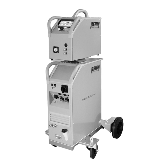
Introduction General description Figure 1: SYNERGIC.ARC 504 WS (Figure does not illustrate standard equipment) -
Page 8: The Principle Of The Inert Gas Metal Welding Process
Use under special requirements may necessitate the observance of particular regulations. If in doubt, ask your responsible safety officer or contact the REHM customer service department. The special instructions listed in the supplier documentation for intended use must be observed. -
Page 9: Symbols Used
Introduction Symbols used Enumerations preceded by a bullet point: General enumerations Typographic distinctions Enumerations preceded by a square: Work or maintenance steps that must be performed the order listed. Section 2.2, Warning symbols on the system Cross reference: here to Section 2.2, Warning symbols on the system Bold text is used for emphasis Note! -
Page 10: Safety Instructions
Safety information Safety instructions Warning symbols in these operating instructions Warnings and This or a symbol that more accurately specifies the risk can be found in all of symbols the safety instructions given in these operating instructions where there is danger to life and limb. -
Page 11: Notes And Requirements
Also observe the safety information signs on the factory floor of the operator. REHM welding machines are, except when REHM expressly states otherwise in Applications writing, for sale to commercial/industrial users only and are intended to be used by commercial/industrial users only. - Page 12 Safety information This Class A equipment is not intended for use in residential areas in which power is supplied from a public low-voltage supply network. Such environments could entail difficulties ensuring electromagnetic compatibility because of interference from wires and radiation. The welding equipment does not comply with IEC 61000- 3-12:2011.
- Page 13 Before using the system be sure to read the information compiled in these operating instructions. These include important instructions on use of the equipment that enable the full technical advantages of the REHM equipment to be exploited. See also the information on repair and maintenance, operating safety and functional reliability.
-
Page 14: Unit Description
Function description Unit description Figure 2: SYNERGIC.ARC 251, compact and gas-cooled Front and rear view (Figure does not illustrate standard equipment) - Page 15 Function description Figure 3: SYNERGIC.ARC 304 W, compact and water-cooled View Front and rear view (Figure does not illustrate standard equipment)
- Page 16 Function description Figure 4: SYNERGIC.ARC 304 W, compact and water-cooled Pole-reversible option (Figure does not illustrate standard equipment)
- Page 17 Function description 9, 23 Figure 5: SYNERGIC.ARC 404 WS with case and water cooling unit Front view (Figure does not illustrate standard equipment)
- Page 18 Function description Figure 6: SYNERGIC.ARC 404 WS with case and water cooling unit Rear view (Figure does not illustrate standard equipment)
- Page 19 Function description Figure 7: SYNERGIC.ARC wire feed case...
- Page 20 Function description Symbol Function/description Control panel – See "Description of controls" Control panel push and rotary encoder Welding torch connection (Euro connection) Polarity selection plug for the torch connection (optional) Connection coolant supply (Blue) Connection coolant return (red) Main switch for switching on/off the welding power source Current socket "negative"...
-
Page 21: Functional Description
Function description Functional description Overview of operating elements Figure 8: SYNERGIC.ARC operating elements and main screen... -
Page 22: Control Panel Description
Function description Control panel description 4.2.1 Operating elements Operating elements Function Main screen BDE mode view: Infinitely variable Operation via rotary encoder with push-knob and buttons for menu selection in the four corners of the screen Fig. 9 Main screen Infinitely variable Main screen BDE mode view: Step-switched... -
Page 23: Operating Elements
Function description 4.2.2 Operating elements The infinitely variable adjustment screen can be selected from the setup screen. => => => The step-switched adjustment screen can be selected from the setup screen. => => => Figure 14: Screen functions... - Page 24 Function description Symbols Description/functions Corner menu welding processes Corner menu operating modes Two-cycle Two-cycle with slope-down Four-cycle Four-cycle with slope-down Spot Spot with slope-down Two-cycle interval Two-cycle interval with slope-down Four-cycle interval Two-cycle interval with slope-down...
- Page 25 Function description Symbols Description/functions Corner menu characteristic curve Material group Material Wire diameter Process Number Corner menu welding process FOCUS.ARC POWER.ARC (MSG) (Selection dependent on filler material and system equipment) Welding current display panel (A) Display panel Voltage (V) Display panel Material thickness (mm) Display panel Wire feed speed (m/min) Display panel SDI BF10...
- Page 26 Function description Symbols Description/functions BF12 Submenu button BF13 MSG parameters BF14 Setup (Settings) BF15 Language BF16 Back button “Home” and “Back” BF17 Fault message Links in the characteristic curve info BF18 Operation and excess temperature display Table 3 Other control functions and submenus...
-
Page 27: Switching On
Switching on SYNERGIC.ARC welding systems are started with the main switch. The screen shows the REHM logo and the unit type for about ten seconds. The display then switches to the main screen [Fig. 9 Main screen]. The last active welding parameters are set. -
Page 28: Corner Menu Functions
Gouging Turning and pressing the rotary encoder [Fig. 13] selects and confirms the process. Pressing the button [BF16] "Back" or "Rehm" returns to the main screen [Fig. 9]. 5.1.1 MSG With infinitely variable MSG welding, very different material transitions and also different types of arc occur depending on the selected arc power and the inert gas used, see also Section 5.4 (welding process). -
Page 29: Corner Menu Operating Mode (Top Right)
Function description Corner menu operating mode (top right) The Operating modes menu [BF2] is activated by pressing the button at the top right of the keypad Fig. 13. This allows selection of the following operating modes: 1. Two-cycle 2. Two-cycle with slope-down 3. -
Page 30: Two-Cycle Operating Mode With Slope-Down
Function description 5.2.2 Two-cycle operating mode with slope-down Two-cycle operating mode procedure with slope-down: 1. Cycle – press the torch trigger The inert gas solenoid valve opens After the set gas pre-flow time has expired the power unit is switched on ... -
Page 31: Four-Cycle Operating Mode
Function description 5.2.3 Four-cycle operating mode Four-cycle welding is recommended for long welding seams. Four-cycle operating mode procedure: 1. Cycle – press the torch trigger The inert gas solenoid valve opens After the set gas pre-flow time has expired the power unit is switched on ... -
Page 32: Four-Cycle Operating Mode With Slope-Down
Function description 5.2.4 Four-cycle operating mode with slope-down Four-cycle operating mode procedure with slope-down: 1. Cycle – press the torch trigger The inert gas solenoid valve opens After the set gas pre-flow time has expired the power unit is switched on. ... -
Page 33: Spot
Function description 5.2.5 Spot The spot welding mode is recommended for welding with a fixed spot welding time from 0.1 seconds. The stationary welding process runs with a fixed spot welding time, unless the torch trigger is released prematurely during the welding. The program runs to the end after expiry of the set spot welding time or after releasing the torch trigger during the welding. -
Page 34: Spot With Slope-Down
Function description 5.2.6 Spot with slope-down Spot operating mode procedure with slope-down: 1. Cycle – press the torch trigger The inert gas solenoid valve opens After the set gas pre-flow time has expired the power unit is switched on ... -
Page 35: Two-Cycle Interval
Function description 5.2.7 Two-cycle interval Interval welding is defined as spot welding with defined pause times. This makes possible apply thinnest filler materials. Interval welding is possible only in the two-cycle operating mode. Welding in the interval welding mode is recommended for welding with a fixed break welding time from 0.1 seconds. -
Page 36: Two-Cycle Interval With Slope-Down
Function description 5.2.8 Two-cycle interval with slope-down Two-cycle interval operating mode procedure with slope-down: 1. Cycle – press the torch trigger The inert gas solenoid valve opens After the set gas pre-flow time has expired the power unit is switched on ... -
Page 37: Four-Cycle Interval
Function description 5.2.9 Four-cycle interval Four-cycle interval operating mode procedure: 1. Cycle – press the torch trigger The inert gas solenoid valve opens Wehn the gas pre-flow time expires, the power unit is switched on. Wire feed runs at the initial wire feed speed ... -
Page 38: Four-Cycle Interval With Slope-Down
Function description 5.2.9 Four-cycle interval with slope-down Two-cycle interval operating mode procedure with slope-down (Slope): 1. Cycle – press the torch trigger The inert gas solenoid valve opens Wehn the gas pre-flow time expires, the power unit is switched on. ... -
Page 39: Characteristic Curve Corner Menu
Function description Characteristic curve corner menu The material group, filler material, diameter of the inserted welding wire, gas, and welding process can be selected and adjusted in the characteristic curve corner menu [BF3]. The selected characteristic curve is displayed on the main screen [BF11]. -
Page 40: Infinitely Variable Operating Panel Description 5.5-5.9
Function description Infinitely variable operating panel description 5.5-5.9 Welding current (A) display panel The required "welding current” display panel [BF5] can be selected by actuating the rotary encoder. The welding current can be set by turning the rotary encoder. The setpoint of the welding current is displayed in idle mode. The actual welding current is displayed during welding. -
Page 41: Switching Level Display Panel
1. One level back by acknowledging a setting 2. One level back by pressing the "Back" button 3. Completely back to the main screen with the button "Main menu" (Rehm). MSG parameters With the welding parameters, the user can individually set the most important parameters for welding, such as: Gas pre-flow time, creep, etc. -
Page 42: Explanation Of Welding Parameters
Function description 6.1.3 Explanation of welding parameters 1 Gas pre-flow time Time between switching on the gas valve and the start of the creep in. This parameter depends on the selected characteristic curve, i.e. the gas pre-flow time can be set individually for each characteristic curve. 2 VD creep Adjustment of the creep speed. -
Page 43: Language Menu
Function description Language menu The available languages are displayed as flags in a selection list. Use the cursor to select a language and confirm by pressing the rotary encoder. The language becomes active immediately. selected language illustrated with cross. Figure 25: Language selection submenu [BF15]... -
Page 44: Saving And Loading Jobs
Function description Saving and loading jobs SYNERGIC.ARC welding systems have four quick-storage keys (P1, P2, P3, P4) so that jobs can be easily saved and loaded. Once the unit settings for recurring welding tasks have been determined, they can thus be quickly recalled and reset on the welding unit. -
Page 45: Setup Submenu
Function description Setup submenu Functions and processes can be defined very conveniently and clearly in the Setup submenu. The required setting is selected by turning the push and rotary encoder [Fig. 13]. The settings are logically structured in various subfolders. Some settings depend on characteristic curve, process, welding system equipment, etc. -
Page 46: Control Lamps
Function description Control lamps Symbol Description Operation/ The symbol OPERATION in black indicates that there is an excess temperature idle voltage at the torch or electrode holder. [BF18] The symbol is located on the left in the characteristic curve info bar The symbol illuminates red and flashes in the event of excess temperature. -
Page 47: Other Functions
Function description Other functions Threading The threading function is used to thread the welding wire into the torch hose set without current. The welding wire is threaded into the torch hose set with the submenu [BF12BF12BF12BF12BF12]. When the "Threading" function button (Figure 28) is pressed, threading is carried out for two seconds at reduced speed. -
Page 48: Water Recirculation Cooling
Function description Water recirculation cooling Depending on equipment variant, standard SYNERGIC.ARC welding system equipment includes a water recirculation cooling system for the welding torch. Temperature monitoring of the power units The welding current is automatically switched off if the permissible temperature of the power components transformer and transistor switch is exceeded. -
Page 49: Accessories And Options
Accessories and options Accessories and options These operating instructions are based on the accessories approved by REHM. Other accessories and wear parts are listed in the extensive welding accessories catalogue. Unit versions, accessories and options SYNERGIC.ARC welding systems unit versions... - Page 50 Accessories and options Accessories: Torches, others upon request Length 4.0m Type RC MAG-24 4m U/D torch 7601530 RC MAG-26 4m U/D torch 7601532 RC MAG-36 4m U/D torch 7601531 RC MAG-240W 4m U/D torch 7601750 RC MAG-401W 4m U/D torch 7601751 RC MAG-555W 4m U/D torch 7601752...
- Page 51 Accessories and options Options Operation in the welding system machine 1381111 Welding system floor mounting 1381110 Advanced trolley (with loading ramp and parking brake) 1381119 Cart for wire feed case 1381150 Preparation for the welding system construction site wagon 1381112 (floor mounting + handle) Welding system upper control panel cover 1381113...
-
Page 52: Commissioning
10.3 Positioning the welding unit CAUTION Set up the REHM welding unit so that the welder has sufficient space in front of the unit to adjust and operate the controls. Transport the unit only in compliance with the applicable accident prevention regulations. - Page 53 Commissioning WARNING CAUTION: For suspended transport (on ropes or chains, for instance), SYNERGIC.ARC welding systems may be attached with crane eyelets only. Fastening to the handles or other parts of the system is not permitted. Injury hazard during attachment to a crane! When the device is attached to a crane, the possibility of the device or its attachments falling poses an injury hazard! ...
-
Page 54: Connecting The Welding Unit
10.5 Cooling the welding unit Place the REHM welding unit so that the air entry and exit ports are not obstructed. The machine can achieve the specified duty cycle only with sufficient ventilation. Ensure that no metal parts, grinding dust, dust or other foreign bodies can enter the unit. -
Page 55: Inserting The Wire
Commissioning 10.8 Connecting the torch For the connection of the MIG/MAG welding torch there is a special connection on the housing (Euro central connection), through which the connections for the welding current, the probe lines and the gas are made. If water-cooled torches are used, the cooling water hoses are connected via quick couplings. -
Page 56: Operation
Carefully read the operating instructions, in particular the Section 2 Safety, before commissioning and before beginning work with this welding power source. Warning! REHM welding equipment should be operated only by persons who are trained and instructed in the use, maintenance and the safety regulations concerning welding systems. -
Page 57: Serious Risks During Welding
Operation 11.4 Serious risks during welding Fire and explosion Materials can be ignited by the electric arc, hot slag, secondary flames or thermal radiation. So remove all combustible materials from the area where welding will be performed and keep a fire extinguisher handy as a preventative measure. There is an explosion risk from the combustible materials particularly due to leaking hoses and containers. - Page 58 Working under elevated electrical risk All REHM inert gas welding systems are suitable for working under elevated electrical risk and therefore carry the S mark. Increased electrical risk exists where: contact with electrical conducting parts by unprotected parts of the body is...
-
Page 59: Practical Instructions For Use
REHM specialist dealer. REHM SYNERGIC.ARC welding systems can be used to weld a wide variety of Weldable materials materials, including unalloyed and alloyed steels, stainless steels, and aluminium. - Page 60 Wire liner Wire liners must be selected to match the various different types of material and wire gauges. The range for this can be found in the REHM welding accessories catalogue. In addition, please refer to the instructions of the torch manufacturer (see operating instructions).
-
Page 61: Faults
Fault Faults 12.1 Safety instructions Warning! If a fault occurs that represents a hazard to persons, systems, and/or the environment, switch off the system immediately and secure it against restarting. Restart operations with the system only after the fault has been eliminated and there is no hazard for persons, machines, and/or the environment. - Page 62 Fault No inert gas Cause: Remedy: Bottle empty Check Pressure reducer defective Check Hose kinked Check Machine gas valve defective Service required! Arc sputters and jumps Cause: Remedy: Contact tip worn Replace contact tip Feed rollers have incorrect diameter Use feed rollers with correct diameter Wire liner very dirty Replace wire liner Electrode and workpiece do not reach working temperature Use thinner wire...
-
Page 63: Error Messages
Fault 12.3 Error messages Error Error Cause Elimination number Mains voltage is below the Switch the unit off and check the 1 000 Mains undervoltage tolerance range mains voltage Mains voltage is above the Switch the unit off and check the 2 000 Mains overvoltage tolerance range... -
Page 64: Maintenance And Repair
REHM original spare parts. If maintenance or repair work is performed on this unit by persons who have not been trained and authorised to carry out the work by REHM, then claims against REHM become void. Before cleaning work begins, the welding unit must be switched off and disconnected from the mains supply. -
Page 65: Maintenance Table
13.3 Cleaning the inside of the unit If the REHM welding unit is used in a dusty environment the inside of the unit must be cleaned at regular intervals by blowing out or vacuuming. The frequency of this cleaning depends on the respective conditions of use, however, it should be carried out at least twice a year. -
Page 66: Cooling Water Check
Dispose of these agents at appropriate collection points for hazardous substances. If maintenance or repair work is performed on this unit by persons who have not been trained and authorised to carry out the work by REHM, then and claims against REHM become void. 13.5 Proper disposal... -
Page 67: Circuit Diagrams
Circuit diagrams Circuit diagrams Figure 29: SYNERGIC.ARC case power source... - Page 68 Circuit diagrams Figure 30: SYNERGIC.ARC wire feed case...
- Page 69 Circuit diagrams Figure 31: SYNERGIC.ARC compact power source...
- Page 70 Circuit diagrams Figure 32: SYNERGIC.ARC water cooling...
-
Page 71: Components And Spare Parts
Components 14.1 Components and spare parts Item Name Part* Comments Item number + A0 ELKO EMV circuit board 251A-504A 690 0881 + A1 Power supply 690 0874 + A2 Main board 251A-404A 690 0901 504A 690 0748 + A2.1/A2.2 Primary IMS 251A-351A 690 0862 404A... - Page 72 Components Item Name Part* Comments Item number - M5 Wire feed motor 410 0075 - M6 Water pump 400V/AC 410 0079 - M7 Fan Ø 172mm 400V/AC 410 0080 - S1 Main switch 420 0096 - T1/T2 Transformer 251A-351A 470 0411 404A 470 0428 504A...
-
Page 73: Characteristic Curve Wire Feeding Unit
Components 15.1 Characteristic curve wire feeding unit SF wire feed plate with accessories, REHM Item No. 4000230: Item Name Part Comments Item number ø Wire infeed nipple - SET blue (Series) Plastic/ 0.6-1.6 2600400 ø 0.6/0.8 7503054 Feed roller V 0.6/0.8 mm solid wire ø... - Page 74 Components...
- Page 75 Components...
- Page 76 Components...
- Page 77 Components...
-
Page 78: Technical Data
Technical data Technical data Technical data SYNERGIC.ARC series Power class 304/311 Setting range 20-255 20-305 20-355 20-405 20-505 Duty cycle (ED) at Imax. (40°C) 50/40 Welding current at 100% ED 270/240 Idle voltage, approximate 67/67 3x400 3x400 Mains connection 3x400 3x400 3x400 +15/-25... - Page 79 Index 17 INDEX " "Intended "Other "Qualification of 13 A and safety Applications C Changes to the system Checking cooling water and the cooler Checks before switching on Cleaning the inside of the unit Commissioning Connect ground cable Connecting the ground cable Connecting the welding unit Contact tips Cooling the welding unit...
- Page 80 Index R Residual dangers S Safety Hazards of non-compliance Safety information 6, 10, 11 Operation Safety instructions Safety symbols Safety symbols Storing the operating instructions Symbols T Table of faults Technical data Threading Torch accessories Type number Typographic distinctions U Uncoiling mandrel setting W ...
- Page 81 The named products have also been developed according to the Ecodesign Directive (2009/125/EC), Regulation EU 2019/1784, Directive 2011/65/EU (RoHS), and Directive 2012/19/EU (WEEE). This declaration is given for the manufacturer: REHM GmbH u. Co. KG Schweißtechnik Ottostr. 2 73066 Uhingen Uhingen, 8/2/2023 submitted by R.
- Page 84 Date of issue 05/2023 | Item no. 7303208...
Need help?
Do you have a question about the SYNERGIC.ARC 251 and is the answer not in the manual?
Questions and answers