
Related Manuals for REHM SYNERGIC.PRO2 170-2


Summary of Contents for REHM SYNERGIC.PRO2 170-2
- Page 1 OPERATING INSTRUCTIONS MIG/MAG GAS-SHIELDED WELDING UNITS SYNERGIC.PRO² 170-2 – 600-4 WS...
-
Page 2: Product Identification
18.03.2014 Rehm GmbH u Co. KG, Uhingen, Germany 2006 The contents of this description is the sole property of Rehm GmbH u. Co. KG. The disclosure or reproduction of this document, the sale and communication of its content are prohibited unless expressly permitted. -
Page 3: Table Of Contents
MIG/MAG inert gas metal arc welding units . 9 1.2.2 Principle of the metal inert gas welding procedure ..............10 1.2.3 Functioning principle of REHM SYNERGIC. PRO welding units ..........10 1.2.4 Correct use ..........................10 Symbols used ........................... 11 SAFETY NOTES ............................ - Page 4 3.13.4 Fan and water pump operation ....................21 3.13.5 Digital voltmeter and ammeter ....................21 3.13.6 REHM automatic threading ......................22 ACCESSORIES ............................ 23 Standard accessories ........................23 Overview of options......................... 23 4.2.1 Wire feed case with trolley ......................24 4.2.2...
- Page 5 Cooling water and cooler inspection ....................37 Correct disposal ..........................37 CIRCUIT DIAGRAMS ..........................38 COMPONENTS OF THE SYNERGIC.PRO UNITS ................44 10.1 List of components with REHM Order numbers ................44 SETTING OF CONTROL MODULE ....................57 TECHNICAL DATA ..........................58 INDEX ..............................59...
-
Page 6: Introduction
Introduction Preface Dear Customer, You have purchased a REHM inert gas welding unit, a branded German product We would like to take this opportunity to thank you for putting your trust in our quality products. Only components of the highest quality are used in the development and manufacture of REHM SYNERGIC. - Page 7 Introduction Areas of use REHM welding units are, unless explicitly permitted in writing by REHM; only for sale to commercial and industrial users and only for use by such. SYNERGIC.PRO MIG/MAG inert gas metal arc welding units should only be used ...
-
Page 8: General Description
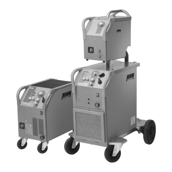
Introduction General description Diagram 1 SYNERGIC.PRO 230-4 , SYNERGIC.PRO² 350-4 WS (picture similar) -
Page 9: Performance Characteristics Of Synergic. Pro
REHM housing form design Increased ergonomics thanks to the constant further development of the REHM design. The protected and well thought out construction achieves the IP23 protection class. This enables welding outside. REHM Industrial control Mains voltage is permanently monitored for fluctuations and compensated appropriately, ensuring optimum, uniform welding results. -
Page 10: Principle Of The Metal Inert Gas Welding Procedure
1.2.4 Correct use REHM welding units are designed to be used to weld various metals such as non-alloyed and alloyed steel, stainless steel and aluminium. You should also pay attention to the special regulations pertaining to your area of application. If anything is unclear, consult your safety officer or contact REHM's customer service department. -
Page 11: Symbols Used
Introduction You should also pay attention to the special notes regarding correct use as set out in the delivery documentation. National regulations regarding the operation of the unit are valid with no restrictions . Correct use also covers the observation of the correct measures with regard to mounting, removal and remounting, taking into service, operation and maintenance as well as disposal. -
Page 12: Safety Notes
Safety notes Safety notes Safety symbols used in these operating instructions Warning notes and symbols This or a symbol more specific to the danger can be found with all safety notes in these operating instructions which carry a risk to life and limb. One of the following signalling words (Danger! Warning! Caution!) indicates the degree of danger: Danger! ... -
Page 13: General
Safety notes General The unit has been developed and constructed in accordance with recognised Dangers of non- technical knowledge. observation However, using the unit may hold dangers for the life and limb of the user or third parties or influence the unit or cause damage to other property. None of the safety measures may be removed or put out of action, as this causes risks and correct use of the unit cannot be guaranteed. -
Page 14: Functional Description
Functional description Functional description Switching on The main switch on the SYNERGIC.PRO is used to activate the main power. The MAINS ON control lamp comes on. The upper digital display for welding voltage shows the software version number (e.g. "P1.0") and the lower display for welding current shows the data record number for the arc (e.g. -
Page 15: Control Leds
Functional description Control LEDs Control lamp Location Colour Functions MAINS ON in the mains Green Power supply voltage applied, switch control on. OPERATION on control panel Green The no-load voltage is available at the wire electrode. The electrode is pushed out of the contact tip of the torch. -
Page 16: 2-Step Function
Functional description Set step switch Turning the step switch changes the no-load voltage and hence also the subsequent welding voltage. The material thickness shown in the lower digital display changes accordingly. Set the step switch so that the material thickness corresponds to the welding job in question. -
Page 17: 4-Step Function
Functional description 3.4.3 4-step function The 4-step welding function is suitable for longer welds. How the 4-step function works: 1. Step – Press torch button Magnet valve for inert gas is opened. Welding voltage is applied Wire feed starts at reduced speed ... -
Page 18: Pulse Function
Program selection The REHM program selection function enables you to immediately set your SYNERGIC.PRO unit to the required welding task, without carrying out time- consuming tryouts, simply by presetting the material type and the wire diameter. -
Page 19: Gouging (Only Available With Synpro 500 And 600)
Functional description The correction knob for wire feed rate (see Diagram 2) should be set to 5 for steel and aluminium, and to 6.5 for CrNi. If the selector switch for program selection is set to manual, these characteristic curves are not used. The most suitable setting of the machine (including wire feed rate, step switch) can be set by the user himself over the entire range. -
Page 20: Sdi - Steplessly Controllable Choke
2-step or 4-step operation, then the welding voltage is switched off automatically with all models. The machine is thus put into the basic state. This provides the user of REHM- SYNERGIC.PRO units additional protection from electrical voltages and fire, as... -
Page 21: Additional Functions
Functional description 3.13 Additional functions 3.13.1 Water circulation cooling The SYNERGIC.PRO 350-4 W, SYNERGIC.PRO 350-4 WS, SYNERGIC.PRO 450-4 W, SYNERGIC.PRO 450-4 WS, SYNERGIC.PRO² 500-4 WS and SYNERGIC.PRO² 600-4 WS units are fitted, as standard, with water circulation cooling for the welding torch. 3.13.2 Temperature monitoring of power elements If the permitted temperature of the power components is exceeded, the welding current is switched off automatically. -
Page 22: Rehm Automatic Threading
Functional description 3.13.6 REHM automatic threading The threading of the welding wire into the torch hose package is carried out by pressing the torch button in 2-step operation with models SYNERGIC.PRO² 170- 450 and in 2-step or 4-step operation with models SYNERGIC.PRO² 500/600, if the welding process is not started within 3 seconds. -
Page 23: Accessories
Accessories Accessories The basis of these operating instructions are the accessories released by REHM. Standard accessories Function and operating instructions 4.2 Overview of options In order to cater to the wide variety of welding requirements, we offer the following options. -
Page 24: Wire Feed Case With Trolley
Accessories 4.2.1 Wire feed case with trolley For the SYNERGIC.PRO² 300-4 - SYNERGIC.PRO² 600-4 case machines, there is an option which allows a wire feed case to be affixed to a trolley with 4 steering castors. This assures maximum mobility in a large working area. 4.2.2 Intermediate hose bundles for SYNERGIC.PRO For the SYNERGIC.PRO²... -
Page 25: Putting Into Operation
(previously known as VGB 15). Setting up the welding unit Set the REHM welding unit in such a way that the welder has sufficient space in front of the unit to control the setting elements and to operate it. Pay attention to the relevant accident regulations when transporting the unit. -
Page 26: Connecting The Welding Unit
Observe the regulations of the appropriate professional associations. Cooling the welding unit Erect the REHM welding unit so that the air intake and outlet are not obstructed. The duty cycle of the power components indicated can be reached only with adequate ventilation. -
Page 27: Connecting The Torch
Putting into operation Connecting the torch There is a special connector (euro central connector) on the housing for connecting the MIG/MAG torch. This forms the connections for welding current, button hoses and gas. When water-cooled torches are used, the cooling water hoses are connected using quick couplings. -
Page 28: Operation
Read the operating instructions, in particular, Chapter 2, Safety, carefully before starting work on this current power source. Warning! REHM welding units may only be operated and maintained by persons who have been educated and trained to operate and maintain welding units. Checks before starting The prerequisites that ... -
Page 29: Switching On
Operation Switching on The main switch on the SYNERGIC.PRO is used to activate the main power. Power switch The MAINS ON control lamp comes on. The upper digital display for welding voltage shows the software version number (e.g. "P2.3") and the lower display for welding current shows the data record number for the arc (e.g. -
Page 30: Set Wire Feed Rate
Circuit diagram. Warning! The work which is necessary to set the automatic burn back must be carried out only by persons who have been trained by REHM. Contact your REHM representative. Gas post-flow time The gas post-flow time is set to 0.2 seconds as standard. The gas post-flow time can be increased to a maximum of 5 seconds using the gas post-flow potentiometer on the circuit board ... -
Page 31: Practical Notes
You should ensure that the current nozzles are selected to suit the wire diameter you are using. Special current nozzles are available for aluminium welding tasks, these are available in various wire diameters and can be found in the REHM welding accessory catalogue. - Page 32 Operation Gas nozzles Gas nozzles are available in various forms and can be found in the REHM welding accessory catalogue Wire feed spirals must be selected in accordance with the material type and wire Wire feed spirals thickness used. The range can be found in the REHM welding accessory...
-
Page 33: Faults
Faults Faults Safety notes Warning! In the event of a fault occurring which may endanger persons, machinery or the surrounding area, deactivate the unit immediately and ensure that it cannot be reactivated. Only restart the unit when the cause of the fault has been eliminated and no further risk is posed to people, machinery and/or surrounding area, Faults should only be eliminated by qualified personnel and all safety notes should be observed. - Page 34 Faults OPERATION control lamp is on constantly Cause: Solution: Torch button defective Check torch button and possibly replace torch Short circuit in torch button circuit Check, possibly replace torch Controller defective Call service TEMPERATURE control lamp on Cause: Solution: Excessive temperature in power component. Allow to cool, ensure that air can circulate freely, if necessary clean machine Maximum duty cycle exceeded...
- Page 35 Faults Wire unwinds in uncontrolled fashion Cause: Solution: Wire spool brake is set too high or too low Set wire spool brake Wire feed problems Hose package should be inflated with every wire change . Feeder spiral and rollers must match the wire diameter Controller defective Call service...
-
Page 36: Repairs And Maintenance
If maintenance or repair work is carried out on this unit by personnel who have not been trained by REHM and thus are not authorised to carry out the work, this will void your guarantee and warranty claims over REHM. -
Page 37: Cleaning The Inside Of The Unit
Cleaning the inside of the unit If the REHM welding unit is used in a dusty environment, then the inside of the unit must be cleaned regularly by vacuuming or blasting. The frequency of this cleaning process will depend on the actual conditions under which the unit is used, but should take place at least twice a year. -
Page 38: Circuit Diagrams
Circuit diagrams Circuit diagrams SYNERGIC.PRO 170-2... - Page 39 Circuit diagrams SYNERGIC.PRO 190-2...
- Page 40 Circuit diagrams SYNERGIC.PRO 230-2 AM SYNERGIC.PRO 230-4 AM SYNERGIC.PRO 280-2 SYNERGIC.PRO 280-4 SYNERGIC.PRO 310-4...
- Page 41 Circuit diagrams SYNERGIC.PRO 250-4 SYNERGIC.PRO 300-4 SYNERGIC.PRO 350-4 SYNERGIC.PRO 450-4 SYNERGIC.PRO 350-4 W SYNERGIC.PRO 450-4 W...
- Page 42 Circuit diagrams SYNERGIC.PRO 300-4S SYNERGIC.PRO 350-4S SYNERGIC.PRO 450-4S SYNERGIC.PRO 350-4WS SYNERGIC.PRO 450-4WS...
- Page 43 Circuit diagrams SYNERGIC.PRO 500-4WS SYNERGIC.PRO 600-4WS...
-
Page 44: Components Of The Synergic.pro Units
Components Components of the SYNERGIC.PRO units 10.1 List of components with REHM Order numbers = Series/Standard O = Optional/customer request = only if air-cooled = only if water-cooled Description 170-2 190-2 230-2 280-2 230-4 280-4 310-4... - Page 45 Components Description 170-2 190-2 230-2 280-2 230-4 280-4 310-4 Securing ring for shaft of 2900123 2900123 2900123 2900123 2900123 2900123 2900123 feed unit 45. Drive gear wheel 4000092 4000092 4000092 46. Feed plate 4000091 4000091 4000103 47. Wire guide 4000012 4000012 4000012 48.
- Page 46 Components 72-73 67-69 Diagram 4: Exploded view of SYNERGIC.PRO² 170-2 – 310-4 (left)
- Page 47 Components Diagram 5: Exploded view of SYNERGIC.PRO² 170-2 – 310-4 (right)
- Page 48 Components = Series/Standard O = Optional/customer request = only if air-cooled = only if water-cooled 450-4 S 500-4 S 600-4 S 350-4 S 450-4 350-4 250-4 300-4 300-4S 450-4 500-4 600-4 350-4 W 350-4 WS 450-4 W Cover 2101819...
- Page 49 Components 450-4 S 500-4 S 600-4 S 350-4 S 450-4 350-4 250-4 300-4 300-4S 450-4 500-4 600-4 350-4 W 350-4 WS 450-4 W 65. Welding cable coupling 4300128 4300128 4300128 4300116 4300116 66. Control lead 14*1.0mm² 3500067 3500067 3500067 3500067 3500067 67.
- Page 50 Components 33 32 Diagram 6 Exploded view of SYNERGIC.PRO² 250-4 – 450-4W (right)
- Page 51 Components 92-96 Diagram 7: Exploded view of SYNERGIC.PRO² 250-4 – 450-4W (left)
- Page 52 Components Diagram 8: Exploded view of SYNERGIC.PRO² 300-4S – 450-4WS (right)
- Page 53 Components Diagram 9: Exploded view of SYNERGIC.PRO² 500-4S – 600-4WS (right)
- Page 54 Components Diagram 10: Exploded view of SYNERGIC.PRO² 300-4S – 600-4WS (left)
- Page 55 Components Figure 11: Exploded view of SYNERGIC.PRO² feed case (right)
- Page 56 Components Figure 12: Exploded view of SYNERGIC.PRO² feed case (left)
-
Page 57: Setting Of Control Module
Setting of control module Setting of control module The control module is designed in such a way that it can be used with all types of machine from SYNERGIC.PRO 170-2 through to SYNERGIC.PRO 600-4 WS. If the control must be replaced, it can be adjusted very easily to the respective model. -
Page 58: Technical Data
Technical data Technical data Overview of types 230-2 280-2 SYNERGIC.PRO 170-2 190-2 310-4 250-4 300-4 350-4 450-4 500-4 600-4 230-4 280-4 30-140 Setting range 30-170 15-230 35-280 35-300 35-250 40-300 40-350 45-450 40-500 40-600 50-190 Duty ratio ( DR ) at I max ( 40°C) Welding current at 100 % duty cycle... -
Page 59: Index
Index INDEX Accessories ..........................23 Accident prevention ........................13 Additional regulations ........................11 Automatic burn back function ....................30 Automatic creep feed ........................30 Automatic feed ........................... 30 Changes to the unit ........................7 Checks before starting ......................... 28 Cleaning the inside of the unit ...................... 37 connect earthing cable ......................... - Page 60 Index Operation safety notes ..........................28 practical notes ..........................31 product identification machine description ........................2 type number ........................... 2 Accessories ..........................23 Product identification ........................2 Protection ............................ 13 Purpose of the document ....................... 7 qualifications staff .......................... 7 Repairs ............................
- Page 61 Directive 2006/95/EWG relating to electrical equipment designed for use within certain voltage limits. This declaration is made on behalf of the manufacturer: REHM GmbH u. Co KG Schweißtechnik Ottostr. 2 73066 Uhingen, Germany Uhingen, 18.03.2014 Declaration made by R.
- Page 62 REHM – Setting the pace in welding and cutting REHM WELDING TECHNOLOGY – The REHM range German Engineering and Production at its best REHM MIG/MAG inert gas welding units Development, construction and production – all under one SYNERGIC.PRO² gas- and water-cooled to 450 A roof –...
Need help?
Do you have a question about the SYNERGIC.PRO2 170-2 and is the answer not in the manual?
Questions and answers