REHM FOCUS.ARC P 300 Operating Instructions Manual
Mig/mag impulse welding systems
Hide thumbs
Also See for FOCUS.ARC P 300:
- Short manual (28 pages) ,
- Operating instructions manual (92 pages)
Table of Contents
Advertisement
Advertisement
Table of Contents

Related Manuals for REHM FOCUS.ARC P 300


Summary of Contents for REHM FOCUS.ARC P 300
- Page 1 OPERATING INSTRUCTIONS MIG/MAG impulse welding systems FOCUS.ARC P 250 - 450...
-
Page 2: Product Identification
18/02/2019 © REHM GmbH u. Co. KG, Uhingen, Germany 2018 The content of this description is the property of REHM GmbH u. Co. KG The copying and distribution of this document, its use and communication of its contents are strictly prohibited unless expressly authorized. -
Page 3: Table Of Contents
List of contents List of contents Product identification INTRODUCTION ..........................6 Foreword ............................6 General description ........................7 1.2.1 The principle of the inert gas metal welding process ............... 8 1.2.2 Intended use ............................ 8 Symbols used ..........................9 SAFETY INSTRUCTIONS ......................10 Warning symbols in these operating instructions ..............10 Warning symbols on the system ....................10 Notes and requirements ......................11... - Page 4 List of contents Display panel Material thickness ....................35 5.10 Display panel Wire feed speed ....................35 5.11 Characteristic curve info bar ..................... 35 SUBMENUS ..........................36 MSG parameters .......................... 36 6.1.1 Parameter settings ........................36 6.1.2 Setting the MSG welding parameters ................... 36 6.1.3 Explanation of welding parameters ....................
- Page 5 List of contents FAULT............................61 12.1 Safety instructions ........................61 12.2 Table of faults ..........................61 12.3 Error messages ..........................63 MAINTENANCE AND REPAIR .....................64 13.1 Safety instructions ........................64 13.2 Maintenance table ........................65 13.3 Cleaning the inside of the unit ....................65 13.4 Cooling water check ........................66 13.5 Proper disposal ..........................66 CIRCUIT DIAGRAMS ........................67...
-
Page 6: Introduction
We thank you for the confidence you have placed in our quality products. Only components of the highest quality are used in FOCUS.ARC P welding systems. To enable a long service life even under the toughest conditions all REHM equipment is manufactured using only parts that comply with our strict quality demands. -
Page 7: General Description
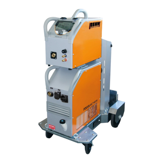
Introduction General description Figure 1: FOCUS.ARC P450 WS (Figure does not illustrate standard equipment) -
Page 8: The Principle Of The Inert Gas Metal Welding Process
REHM welding machines are, except when this is expressly stated in writing by REHM, only for sale to commercial / industrial users and are only intended to be used by commercial / industrial users. The machines may only be operated by persons who trained in the use and maintenance of welding equipment. -
Page 9: Symbols Used
Introduction Symbols used • Typographic Enumerations proceeded by a bullet point: General enumerations distinctions Enumerations proceeded by a square: Work or maintenance steps that must be performed in the order listed. ➔ Section 2.2, Warning symbols on the system Cross section: here to Section 2.2, Warning symbols on the system Bold text is used for emphasis Note! -
Page 10: Safety Instructions
Safety information Safety instructions Warning symbols in these operating instructions This or a symbol that more accurately specifies the risk can be found in all Warnings and of the safety instructions given in these operating instructions where there symbols is danger to life and limb. One of the signal words below (Danger!, Warning!, Caution!) is used to indicate the severity of the risk: …warning of immediate danger. -
Page 11: Notes And Requirements
REHM welding machines are, except when this is expressly stated in writing by Applications REHM, only for sale to commercial / industrial users and are only intended to be used by commercial / industrial users. The FOCUS.ARC P MIG/MAG gas welding equipment is designed in accordance... -
Page 12: Safety Information
See also the information on repair and maintenance, operating safety and functional reliability. These operating instructions are not a substitute for the practical teaching by the REHM service personnel. Documentation for any additional operation that may be present must also be observed. -
Page 13: Unit Description
Function description Unit description Figure 2: FOCUS.ARC P 450WS with case and water cooling unit Front view (Figure does not illustrate standard equipment) - Page 14 Function description Figure 3: FOCUS.ARC P 300W, compact and water cooled Front view (Figure does not illustrate standard equipment)
- Page 15 Function description Figure 4: FOCUS.ARC P 450 Rear view (Figure does not illustrate standard equipment)
- Page 16 Function description Figure 5: FOCUS.ARC P wire feed case...
- Page 17 Function description Symbol Function / description Control panel - See "Description of controls" Control panel push and rotary encoder Welding torch connection (Euro connection) Remote control socket (7 pin) Connection coolant supply (Blue) Connection coolant return (red) Main switch for switching on/off the welding current source Current socket "negative"...
-
Page 18: Functional Description
Function description Functional description Overview of the operating elements Figure 6: Operating element and main screen FOCUS.ARC P... -
Page 19: Control Panel Description
Function description Control panel description 4.2.1 Operating elements Controls Function Main screen Operation via rotary encoder with push- knob and buttons for menu selection in the 4 corners of the screen Fig. 7 Main screen Function buttons (from left to right) Submenu List of all Button... -
Page 20: Operating Elements
Function description 4.2.2 Operating elements Figure 11: Screen functions Symbols Description / function Corner menu welding processes MSG welding Corner menu operating modes 2 cycle 2 cycle with slope-down 4 cycle 4 cycle with slope-down Spot Spot with slope-down Interval Interval with slope-down... - Page 21 Function description Symbols Description / function Corner menu characteristic curve Material Wire diameter process Corner menu welding process MSG Normal Power Arc Power Puls II Focus.Puls Root Display panel Welding current (A) Display panel Voltage (V) Display panel Material thickness (mm) Display panel Wire feed speed (m/min)
- Page 22 Function description Symbols Description / function BF12 Sub menu buttons BF13 MSG parameters BF14 Language Function Assist (not available at BF15 present) BF16 Function Job Memory (Program) BF17 Setup (Settings) Back button “Home” and “Back” BF18 BF19 Fault message Links in the characteristic curve info BF20 Display Operation and excess temperature...
-
Page 23: Switching On
The FOCUS.ARC P welding system is started with the mains switch. The screen shows the Rehm logo and the unit type for approximately 10 seconds. The display then switches to the main screen [Fig. 7 Main screen]. The last active welding parameters are set. -
Page 24: Corner Menu Functions
• MIG/MAG (MSG inert gas metal welding) Turning and pressing the rotary encoder [Fig. 10] selects and confirms the process. Pressing the button [BF17] "Back or "Rehm" returns to the main screen [Fig. 7]. 5.1.1 Conventional MIG/MAG(MSG) welding With continuous MSG welding, very different material transitions and also different types of arc occur depending on the selected arc power and the inert gas used, see also Section 5.4 (welding process). -
Page 25: Cycle Operating Mode
Function description 5.2.1 2 cycle operating mode The 2 cycle mode is recommended for fast, controlled tacking and manual spot welding. 1. cycle Operate the torch trigger The inert gas solenoid valve opens After the set gas pre-flow time has expired the power unit is switched on ... -
Page 26: Cycle Operating Mode With Slope-Down (Slope)
Function description 5.2.2 2 cycle operating mode with slope-down (Slope) 2 cycle operating mode procedure with slope-down (Slope): 1. cycle Operate the torch trigger The inert gas solenoid valve opens After the set gas pre-flow time has expired the power unit is switched on ... -
Page 27: Cycle Operating Mode
Function description 5.2.3 4 cycle operating mode 4 cycle welding is recommended for longer welding seams. 4 cycle operating mode procedure: 1. cycle Operate the torch trigger The inert gas solenoid valve opens After the set gas pre-flow time has expired the power unit is switched on ... -
Page 28: Cycle Operating Mode With Slope-Down (Slope)
Function description 5.2.4 4 cycle operating mode with slope-down (Slope) 4 cycle operating mode procedure with slope-down (Slope): 1. cycle Operate the torch trigger The inert gas solenoid valve opens After the set gas pre-flow time has expired the power unit is switched on. ... -
Page 29: Spot
Function description 5.2.5 Spot The spot welding mode is recommended for welding with a fixed spot welding time from 0.1 seconds. The stationary welding process runs with a fixed spot welding time, unless the trigger is released prematurely during the welding. The program runs to the end after expiry of the set spot welding time or after releasing the torch trigger during the welding. -
Page 30: Spot With Slope-Down (Slope)
Function description 5.2.6 Spot with slope-down (Slope) Spot operating mode procedure with slope-down (Slope): 1. cycle Operate the torch trigger The inert gas solenoid valve opens After the set gas pre-flow time has expired the power unit is switched on ... -
Page 31: Cycle Interval
Function description 5.2.7 2 cycle interval Interval welding is defined as spot welding with defined pause times. This makes possible apply thinnest filler materials. Interval welding is only possible in the 2 cycle operating mode. Welding in the interval welding mode is recommended for welding with a fixed break welding time from 0.01 seconds. -
Page 32: Cycle Interval With Slope-Down (Slope)
Function description 5.2.8 2 cycle interval with slope-down (Slope) 2 cycle interval operating mode procedure with slope-down (Slope): 1. cycle Operate the torch trigger The inert gas solenoid valve opens After the set gas pre-flow time has expired the power unit is switched on ... -
Page 33: Corner Menu Characteristic Curve
Function description Corner menu characteristic curve The material, the wire diameter of the inserted welding wire, the gas and the welding process can be selected and adjusted in the corner menu characteristic curve [BF3]. The selected characteristic curve is displayed on the main screen [BF11]. -
Page 34: Focus Puls
Function description 5.4.3 Focus Puls The Focus Puls welding process can also be selected for pulsing. • Pulse arc U/I – controlled • Voltage controlled bead detachment • Perfect arc length • Very good flow properties, flat weld seam geometry •... -
Page 35: Display Panel Lbl Correction
Function description Display panel LBL correction The required "LBL correction" display panel [BF10] can be selected by actuating the rotary encoder. The arc length can be continuously adjusted by turning the rotary encoder. Display panel Material thickness The required "material thickness" display panel [BF7] can be selected by actuating the rotary encoder. -
Page 36: Submenus
1. One level back by acknowledging a setting 2. One level back by pressing the "Back" button 3. Completely back to the main screen with the button "Main menu" (Rehm). MSG parameters With the welding parameters, the user can individually set the most important parameters for welding, such as: Gas pre-flow time, creep, etc. - Page 37 Function description Figure 20: Submenu MSG parameters...
-
Page 38: Explanation Of Welding Parameters
Function description 6.1.3 Explanation of welding parameters Gas pre-flow time Time between switching on the gas valve and the start of the creep in. This parameter depends on the selected characteristic curve, i.e. the gas pre-flow time can be set individually for each characteristic curve. Creep Adjustment of the creep speed. - Page 39 Function description End-crater current The end crater current is the welding current to which the welding current is reduced, within the set slope-down time, when the welding process is ended. Selecting the appropriate end crater current enables: • Prevention of notches and end crater cracks at the end of the weld seam due to rapid cooling of the weld pool •...
-
Page 40: Language Menu
Function description Language menu The available languages are displayed as flags in a selection list. Use the cursor to select a language and confirm by pressing the rotary encoder. The language becomes active immediately. The selected language is illustrated by a box with cross. Figure 21: Sub menu Language selection [BF14]... -
Page 41: Saving And Loading Jobs
Function description Saving and loading jobs The Jobs submenu allows loading, saving and deleting of up to 12 jobs. The jobs can be saved and loaded under a freely selectable name in a freely selectable folder. Once the unit settings for recurring welding tasks have been determined, they can be quickly recalled and reset on the welding unit. - Page 42 Function description Press the "Home" button[BF18] to return to the main screen. Figure 23: Submenu Job / Text input Symbol Function Cursor left Cursor right New line Delete letter to the left of the cursor Table 4 Explanation symbols Text input...
-
Page 43: Load Job
Function description 6.3.2 Load job Pressing the "Submenus" button [BF12] accesses a selection list (drop down list) for the existing submenu. Select the Job folder by turning and pressing the rotary encoder Select the required field by turning and pressing the rotary encoder. The selected field has a blue frame. -
Page 44: Delete Job
Function description 6.3.3 Delete job Pressing the "Submenus" button [BF12] accesses a selection list (drop down list) for the existing submenu. Select the Job folder by turning and pressing the rotary encoder Select the required field by turning and pressing the rotary encoder. The selected field has a blue frame. -
Page 45: Rename Job
Function description 6.3.4 Rename job Pressing the "Submenus" button [BF12] accesses a selection list (drop down list) for the existing submenu. Select the Job folder by turning and pressing the rotary encoder Select the required job by turning and pressing. ... -
Page 46: Setup Submenu
Function description Setup submenu Functions and processes can be defined very conveniently and clearly in the Setup submenu. The required setting is selected by turning the push and rotary encoder [Fig. 10]. The selected line is highlighted in orange. ... - Page 47 Function description Name Setting possibility Description Double pulse Active Inactive Energy saving mode ---- Inactive Time Minutes Idle time until energy saving mode becomes active Colour scheme Light Dark Gas test: Time (Seconds) Hold mode Inactive Action Action and time Hold time Seconds LBL correction Type...
-
Page 48: Control Lamps
Function description Control lamps Symbol Description Operation/ The symbol OPERATION in black indicates that there is an excess temperature open circuit voltage at the torch or electrode holder. [BF20] The symbol is located on the left in the characteristic curve info bar The symbol illuminates red and flashes in the event of excess temperature. -
Page 49: Other Functions
Function description Other functions Threading The threading function is used to thread the welding wire into the torch hose set without current. The welding wire is threaded into the torch hose set by means of the push button above the feed unit (Fig. 4). By pressing the pushbutton "Threading", threading is carried out for 2 seconds at reduced speed. -
Page 50: Water Recirculation Cooling
Function description Water recirculation cooling The compact units FOCUS.ARC P 250W, 300W, 350W, 400W and 450W as well as the units with separate wire feed case FOCUS.ARC P 250WS, 300WS, 350WS, 400WS and 450WS are equipped as standard with water recirculation cooling for the welding torch. -
Page 51: Accessories And Options
FOCUS.ARC P 250 S 0.8/1.0 operation in the wire feed case 1307047 FOCUS.ARC P 250 WS 0.8/1.0 operation in the wire feed case 1307048 FOCUS.ARC P 300 S 0.8/1.0 operation in the wire feed case 1307057 FOCUS.ARC P 300 WS 0.8/1.0 operation in the wire feed case 1307058 FOCUS.ARC P 350 S 1.0/1.2 operation in the wire feed case... - Page 52 Accessories and options FOCUS.ARC P Accessories Intermediate hose set Water cooled Item no. ZWIPA MSG 50MM² 1.4M WATER COOLED 7503018 ZWIPA MSG 50MM² 5M WATER COOLED 7503019 ZWIPA MSG 50MM² 10M WATER COOLED 7503020 ZWIPA MSG 70MM² 1.4M WATER COOLED 7503026 ZWIPA MSG 70MM²...
- Page 53 Accessories and options Torch MIG/MAG water cooled Item no. Torch MAG W 540D 4m 7601730 Torch MAG W 540D 5m 7601732 Torch MAG W 340D 7 3m UD 7601717 Torch MAG W 340D 7 4m UD 7601719 Torch MAG W 340D 7 5m UD 7601721 Torch MAG W 440D 7 3m UD 7601723...
- Page 54 Accessories and options Feed rollers for wire feeding unit Individual feed rollers for solid wire Item no. Feed roller 0.6 – 0.8 mm solid wire 7503054 Feed roller 0.8 – 1.0 mm solid wire 7503055 Feed roller 1.0 – 1.2 mm solid wire 7503053 Feed roller 1.2 –...
-
Page 55: Commissioning
10.3 Positioning the welding unit Place the REHM welding system so that the welder has sufficient space in front of the unit to adjust and operate the controls. Transport the unit only under compliance with the applicable accident prevention regulations. -
Page 56: Connecting The Welding Unit
Always close the bottle valve after completing work. Observe the regulations of the respective professional associations. 10.5 Cooling the welding unit Place the REHM welding unit so that the air entry and exit ports are not obstructed. The machine can only achieve the specified duty cycle with sufficient ventilation. -
Page 57: Inserting The Wire
Commissioning Important! When using a gas-cooled torch on a water-cooled system, the water connections must be connected via a hose bridge or the water cooling must be set to "Off" in the Setup submenu so that the water pump is not damaged. -
Page 58: Operation
11.4 Practical instructions for use The following practical instructions for use can only provide an overview of the various applications of REHM FOCUS.ARC P welding systems. If you have any questions about special welding tasks, materials, inert gases or welding equipment, please refer to the relevant technical literature or to the REHM specialist dealer. -
Page 59: Type Focus.arc P
Operation The REHM FOCUS.ARC P inert gas welding systems can be used to weld a Weldable materials wide variety of materials, e.g. unalloyed and alloyed steels, stainless steels and aluminium. Wire electrodes Various different wire diameters and materials are offered and used for MIG/MAG welding. - Page 60 Operation Care must be taken to ensure that the pressure on the wire is set correctly via the feed rollers. With aluminium, the pressure should be as low as possible, but still allow the wire to be transported safely. In the case of steel and stainless steel, the pressure should be so strong that the wire coil can still be stopped manually while the drive is running.
-
Page 61: Fault
Fault Fault 12.1 Safety instructions Warning! If a fault occurs that represents a hazard to persons, systems and/or the environment, switch off the system immediately and secure against restarting. Only restart operations with the system after the fault has been eliminated and no hazard exists for persons, machines and/or the environment. - Page 62 Fault No inert gas Cause: Remedy: Bottle empty Check Pressure reducer defective Check Hose kinked Check Machine gas valve defective Service required ! Arc sputters and jumps Cause: Remedy: Contact tip worn Replace contact tip Feed rollers have incorrect diameter Use feed rollers with correct diameter Wire liner very dirty Replace wire liner...
-
Page 63: Error Messages
Fault 12.3 Error messages Error Error Cause Elimination number Mains voltage is below the Switch the unit off and check the Mains undervoltage tolerance range mains voltage Mains voltage is above the Switch the unit off and check the Mains overvoltage tolerance range mains voltage The bus communication... -
Page 64: Maintenance And Repair
REHM original spare parts. If maintenance or repair work is performed on this unit by persons who have not been trained and authorised to carry out the work by REHM, then claims against REHM become void. Before beginning cleaning work the unit must be switched off and disconnected from the mains supply. -
Page 65: Maintenance Table
13.3 Cleaning the inside of the unit If the REHM welding unit is used in a dusty environment the inside of the unit must be cleaned at regular intervals by blowing out or vacuuming. The frequency of this cleaning depends on the respective conditions of use, however, it should be carried out at least twice a year. -
Page 66: Cooling Water Check
Dispose of these agents at appropriate collection points for hazardous substances. If maintenance or repair work is performed on this unit by persons who have not been trained and authorised to carry out the work by REHM, then and claims against REHM become void. 13.5 Proper disposal... -
Page 67: Circuit Diagrams
Circuit diagrams Circuit diagrams Figure 28: FOCUS.ARC P current source... -
Page 68: Focus.arc P
Circuit diagrams Figure29: FOCUS.ARC P wire feed case... - Page 69 Circuit diagrams Figure30: FOCUS.ARC P water cooling...
-
Page 70: Characteristic Curve Current Source
Components 14.1 Characteristic curve current source Pos. Name Part* Comments Item number + A0 ELKO EMV circuit board 250A-300A 690 0846 350A-450A 690 0847 + A1 Power supply 690 0777 + A2 Main board 250A-300A 690 0747 350A-450A 690 0748 + A2.1/A2.2 Primary IMS 250A-300A 690 0852... - Page 71 Circuit diagrams Pos. Name Part* Comments Item number - T1/T2 Transformer 250A-300A 470 0411 350A-450A 470 0428 - T3 PFC choke 250A-300A 470 0412 350A-450A 470 0429 - T4 Autotransformer (water-cooled) 470 0430 - V1 Main rectifier 250A-300A 530 0142 350A-450A 530 0144 - X4...
-
Page 72: Components And Spare Parts
Components Components and spare parts 15.1 Characteristic curve wire feeding unit Wire feeding unit REHM Item no. 400 0194: Pos. Name Part Comments Item number ø Wire infeed nipple - SET blue (Series) Plastic/ 0.6-1.6 2600400 ø 0.6/0.8 7503054 ø... - Page 73 Components...
- Page 74 Components...
- Page 75 Components...
- Page 76 Components...
-
Page 77: Technical Data
Technical data Technical data Type overview Technical data FOCUS.ARC P Series Power class Setting range 20-250 20-300 20-350 20-400 20-450 Duty cycle (ED) at Imax. (40°C) Weld current at 100 % ED Idle voltage, approx. 3x400 3x400 Mains connection 3x400 3x400 3x400 +15/-25... -
Page 78: Index
Index INDEX Intended Qualification and health Applications Changes to the system Checking cooling water and the cooler Checks before switching on Cleaning the inside of the unit Commissioning Connect grounding cable Connecting the grounding cable Connecting the welding unit Contact tips Cooling the welding unit Electrodes Fault... - Page 79 Index Safety Hazards of non-compliance Safety information 6, 10, 11 Operation Safety instructions Safety symbols Safety symbols Storing the operating instructions Symbols Table of faults Technical data Threading Torch accessories Type number Typographic distinctions Uncoiling mandrel setting Warning symbols on the system Warnings and symbols Presentation Water cooling for MIG/MAG welding torches...
- Page 80 EC. Directive 2006/42/EC article 1, paragraph 2 the above mentioned products fall exclusively within the scope of the directive 2006/95/EC relating to electrical equipment designed for use within certain voltage limits. This declaration is given for the manufacturer: REHM GmbH u. Co. KG Schweißtechnik Ottostr. 2 73066 Uhingen Uhingen, 18/02/2019 submitted by R.
- Page 82 REHM – The benchmark for modern welding and cutting REHM WELDING TECHNOLOGY – The REHM range German Engineering and Production at its best ▪ REHM MIG/MAG inert gas welding units Development, design and production – all under one roof –...
Need help?
Do you have a question about the FOCUS.ARC P 300 and is the answer not in the manual?
Questions and answers