Sign In
Upload
Download
Table of Contents
Contents
Add to my manuals
Delete from my manuals
Share
URL of this page:
HTML Link:
Bookmark this page
Add
Manual will be automatically added to "My Manuals"
Print this page
×
Bookmark added
×
Added to my manuals
Manuals
Brands
REHM Manuals
Welding System
BARRACUDA RTC 60
Operating instructions manual
REHM BARRACUDA RTC 60 Operating Instructions Manual
Plasma arc cutting
Hide thumbs
1
2
Table Of Contents
3
4
5
6
7
8
9
10
11
12
13
14
15
16
17
18
19
20
21
22
23
24
25
26
27
28
29
30
31
32
33
34
35
36
37
38
39
40
41
42
43
44
45
46
47
48
49
50
51
52
53
54
55
page
of
55
Go
/
55
Contents
Table of Contents
Troubleshooting
Bookmarks
Table of Contents
Product Identification
Table of Contents
1 Introduction
Foreword
General Description
Performance Features of BARRACUDA Cutting Equipment
Principle of Plasma Arc Cutting
Area of Application of Plasma Cutting Equipment
Function Principle of REHM BARRACUDA Cutting Equipment
Proper Use
Symbols Used
2 Safety Instructions
Safety Symbols in These Operating Instructions
Warning Symbols on the Equipment
2.3 General
3 Description of Function
Preparations for Cutting
Mains Connection and Power-Up
Adjustment of Compressed Air - Gas Test
Operating Modes
2-Step Operating Mode
Choosing the Cutting Current
Nozzle Selection
Cutting Operation
General Description
The REHM Control Panel
Symbols and Their Meanings
Operating Modes
2-Step Function Sequence
Possible Applications
Cutting of Perforated Sheets
Hole-Piercing
Gouging
Weld Preparation
Circle Cutting
Machine Functions
Gas Pre-Flow
Soft Start
Quick Start
Safety Shut-Down
Post-Purge Gas Flow Time
Safety Contact in Plasma Torch
Detection of Phase Failure
4 Accessories
Standard Accessories
Options
80A Torch for RTC 100 and RTC 150
Automatic Torch
Torch Accessories
Air Filter Attachment
Mechanised Interlock
Special Voltages
Torches and Accessories
RTC 60 Machine Configuration
Standard Accessories for RTC 60
Plasma Torches A80 and P80 Aut
Machine Configuration RTC 100 / RTC 150
Standard Accessories RTC 100 / RTC 150
Plasma Torches R145 and R145P
Accessories for Torch R145
Circle Cutting Equipment and Magnet Clamps
5 Commissioning
Safety Instructions
Working under Increased Electrical Danger in Accordance with the Provisions of IEC 974, en 60974-1 and VBG 15 (S)
Transport and Set-Up of the Plasma Cutting Equipment
Connection of the Plasma Cutting Equipment
Cooling of the Plasma Cutting Equipment
Compressed Air Supply
Guidelines for Working with Cutting Current Sources
Connection of Workpiece Return Cables/Torch
Recommended Cross-Sections of Welding Power Supply Cables
5.10 Connection to Jigs
6 Operation
Safety Instructions
Electrical Hazards
Information for Your Personal Safety
Fire Protection
Ventilation
Checks before Switching on
Connection of the Earthing Cable
7 Faults
Safety Instructions
Troubleshooting Table
8 Maintenance Work
Safety Instructions
Maintenance Table
Cleaning of Equipment Interior
Proper Waste Disposal
9 Circuit Diagrams
10 List of Components
10.1 Sparepart List REHM RTC
11 Mechanised Interlocks
RTC Units with 7-Pin Interface (Only for RTC 100 and RTC 150)
RTC Units with 17-Pin Interface (Only for RTC 100 and RTC 150)
Connection Schematic for 7-Pole Mechanised Cutting Interface
Connection Schematic for A-Pole Mechanised Cutting Interface
Technical Data
12 Technical Data51
13 Index
Ec Declaration of Conformity
Advertisement
Quick Links
1
General Description
Download this manual
GB
OPERATING INSTRUCTIONS
Plasma arc cutting
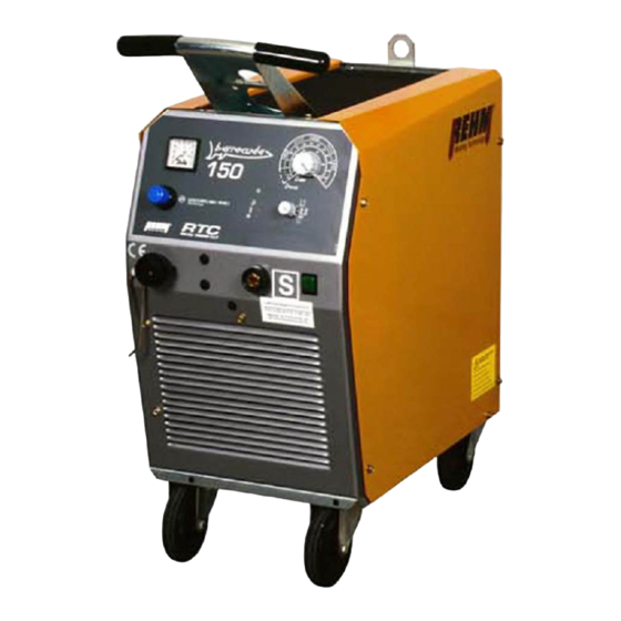
BARRACUDA RTC 60 / 100 / 150
Table of
Contents
Previous
Page
Next
Page
1
2
3
4
5
Advertisement
Table of Contents
Need help?
Do you have a question about the BARRACUDA RTC 60 and is the answer not in the manual?
Ask a question
Questions and answers
Subscribe to Our Youtube Channel
Related Manuals for REHM BARRACUDA RTC 60
Welding System REHM BARRACUDA RTC 100 Operating Instructions Manual
Plasma arc cutting (55 pages)
Welding System REHM BARRACUDA RTC 150 Operating Instructions Manual
Plasma arc cutting (55 pages)
Welding System REHM BARRACUDA 45i Operating Instructions Manual
Plasma cutting device (36 pages)
Welding System REHM BARRACUDA 65i Operating Instructions Manual
Plasma cutting device (36 pages)
Welding System REHM BARRACUDA 105i Operating Instructions Manual
Plasma cutting device (36 pages)
Welding System REHM BARRACUDA 125i Operating Instructions Manual
Plasma cutting device (36 pages)
Welding System Rehm INVERTIG.PRO digital 240 DC, 240 AC/DC Operating Instructions Manual
(88 pages)
Welding System REHM SYNERGIC.PRO 251 Short Manual
(16 pages)
Welding System REHM TIGER 170 DC Operating Instructions Manual
Tig welding units (64 pages)
Welding System REHM FOCUS.ARC P Series Operating Instructions Manual
Mig/mag impulse welding systems (92 pages)
Welding System REHM FOCUS.ARC P Series Short Manual
(28 pages)
Welding System rehm Tiger 170 Operating Instructions Manual
(63 pages)
Welding System Rehm TIGER DIGITAL 230 AC/DC ULTRA Operating Instructions Manual
(83 pages)
Welding System REHM INVERTIG i 260 DC Operating Instructions Manual
Tig inert gas welding equipment (92 pages)
Welding System REHM SYNERGIC.PRO2 170-2 Operating Instructions Manual
Mig/mag gas-shielded welding units (62 pages)
Welding System REHM TIGER 180 AC/DC HIGH Operating Instructions Manual
Tig inert gas welding units (68 pages)
This manual is also suitable for:
Barracuda rtc 100
Barracuda rtc 150
Table of Contents
Print
Rename the bookmark
Delete bookmark?
Delete from my manuals?
Login
Sign In
OR
Sign in with Facebook
Sign in with Google
Upload manual
Upload from disk
Upload from URL


Need help?
Do you have a question about the BARRACUDA RTC 60 and is the answer not in the manual?
Questions and answers