
Subscribe to Our Youtube Channel
Related Manuals for IFM VSE150


Summary of Contents for IFM VSE150
- Page 1 Operating instructions Diagnostic electronics with PROFINET-IO interface for vibration sensors VSE150...
-
Page 2: Table Of Contents
VSE150 Diagnostic electronics with PROFINET-IO interface for vibration sensors Contents Safety instructions............ -
Page 3: Safety Instructions
Diagnostic electronics with PROFINET-IO interface for vibration sensors VSE150 1 Safety instructions • The unit described is a subcomponent for integration into a system. – The system architect is responsible for the safety of the system. – The system architect undertakes to perform a risk assessment and to create documentation in accordance with legal and normative requirements to be provided to the operator and user of the system. -
Page 4: Preliminary Note
VSE150 Diagnostic electronics with PROFINET-IO interface for vibration sensors 2 Preliminary note You will find instructions, technical data, approvals, accessories and further information using the QR code on the unit / packaging or at www.ifm.com. 2.1 Symbols used Requirement Instructions Reaction, result [...]... -
Page 5: Intended Use
Diagnostic electronics with PROFINET-IO interface for vibration sensors VSE150 3 Intended use The device has been designed for process value monitoring, vibration monitoring and analysis of dynamic signals. -
Page 6: Sensor Functions
VSE150 Diagnostic electronics with PROFINET-IO interface for vibration sensors 4 Sensor functions The diagnostic electronics has • 2 analogue inputs • 4 dynamic inputs • 1 analogue or digital output • 1 digital output • 1 TCP/IP parameter setting interface •... -
Page 7: Function Description
The firmware can only be updated via the VES004 PC software. Only the firmware of the entire device can be updated. w Firmware and operating software → download area www.ifm.com w A description of all firmware parameters and their meaning → VES004 PC software manual. -
Page 8: Installation
VSE150 Diagnostic electronics with PROFINET-IO interface for vibration sensors 5 Installation u Mount the unit in a control cabinet with a protection rating of at least IP 54 to ensure protection against accidental contact with dangerous contact voltages and against atmospheric influence. -
Page 9: Electrical Connection
Diagnostic electronics with PROFINET-IO interface for vibration sensors VSE150 6 Electrical connection The national and international regulations for the installation of electrical equipment must be adhered to. Avoid contact with dangerous contact voltages. u Disconnect power. u Connect device, connection via Combicon connectors (pre-mounted). -
Page 10: Ethernet Connection
VSE150 Diagnostic electronics with PROFINET-IO interface for vibration sensors Wiring of sensors 1...4 (S1...S4) according to their use Sensor IEPE/VSP 0...20 mA BN: L+ (+ 9 V) not connected (n.c.) not connected (n.c.) WH: Signal IEPE + Signal BU: GND... -
Page 11: Profinet Io Interface
Diagnostic electronics with PROFINET-IO interface for vibration sensors VSE150 7 PROFINET IO interface 7.1 Manufacturer and device information Manufacturer Requirement Parameter Vendor ifm electronic gmbh Vendor ID 0x0136 Unit Name VSE150 Device ID 0x0B00 Order ID VSE150 PROFINET device type PROFINET IO device... -
Page 12: Profinet Io Data Model
VSE150 Diagnostic electronics with PROFINET-IO interface for vibration sensors 7.4 PROFINET IO data model The PROFINET IO data to be transferred is selected via the VES004 PC software. After respective parameter setting of the requested input and output data the PROFINET IO data model is created flexibly and transferred to the device via writing the parameter set. - Page 13 Diagnostic electronics with PROFINET-IO interface for vibration sensors VSE150 Input (PLC) Error Word 2 bytes Error codes for description of error in object state 0x0000: no error 0x0001: internal error 0x0002: calculation error 0x0004: speed out of range 0x0008: speed not stable...
- Page 14 VSE150 Diagnostic electronics with PROFINET-IO interface for vibration sensors Input (PLC) Average value of the his- • Real or DINT with factor 4 bytes Unit-based average value of tory the current history entry of • Big or the object Little Endian •...
- Page 15 Diagnostic electronics with PROFINET-IO interface for vibration sensors VSE150 Input (PLC) Self-test Byte 1 byte Bit pattern result Bit1 - sensor 1 Bit2 - sensor 2 Bit3 - sensor 3 Bit4 - sensor 4 Note on evaluation 0x00: Sensors OK...
-
Page 16: Profinet Io Functions
VSE150 Diagnostic electronics with PROFINET-IO interface for vibration sensors Output (PLC) Do self-test Byte 1 byte Execute self-test Note A value change from 0 to ≠ 0 starts the self-test After completion of the self- test, the unit automatically switches to the “Monitoring”... -
Page 17: Shared Device
Diagnostic electronics with PROFINET-IO interface for vibration sensors VSE150 I&M data Access / data type Presets IM_VERSION Read / 2 bytes 0x0101 IM_SUPPORTED Read / 2 bytes 0x000E I&M 1 I&M data Access / data type Presets TAG_FUNCTION Read/write / 32 bytes... -
Page 18: Lldp - Link Layer Discovery Protocol
VSE150 Diagnostic electronics with PROFINET-IO interface for vibration sensors Requirement Parameter Description Simple Network Management Protocol A UDP-based communication protocol (User Datagram Proto- col) for maintenance and monitoring of network components. PROFINET uses this protocol, for example, for creating topol- ogy information. -
Page 19: Behaviour If Parameter Set Is Changed
Diagnostic electronics with PROFINET-IO interface for vibration sensors VSE150 7.7 Behaviour if parameter set is changed Writing of the parameter set (even without changes) or changing the system mode of the diagnostic electronics to “set-up” triggers an initialisation (reboot) of the fieldbus module. -
Page 20: Factory Setting
VSE150 Diagnostic electronics with PROFINET-IO interface for vibration sensors 8 Factory setting On delivery there are the following factory settings: IP settings, parameter setting interface, delivery status. 8.1 General factory setting Requirement Parameter Parameter set None Host Name no name assigned IP address 192.168.0.1... -
Page 21: Parameter Setting
Diagnostic electronics with PROFINET-IO interface for vibration sensors VSE150 9 Parameter setting The device parameters are set exclusively via the VES004 PC software. All parameters of the configured application are bundled in a parameter set and transferred to the device. For a detailed description of all parameters and possible configurations we refer you to the VES004 software manual. -
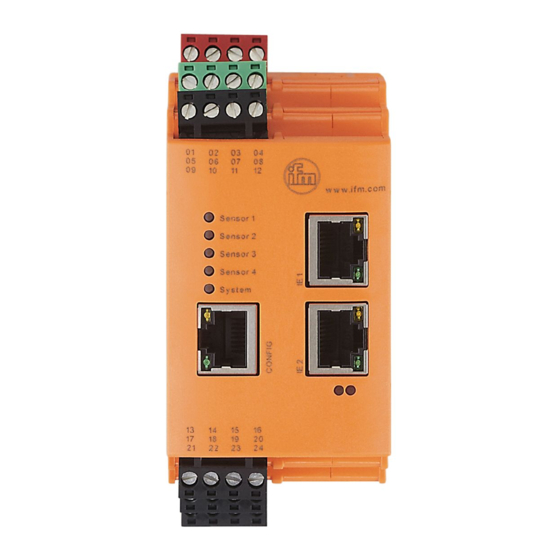
Page 22: Operating And Display Elements
VSE150 Diagnostic electronics with PROFINET-IO interface for vibration sensors 10 Operating and display elements 1: Config: TCP/IP, IP address 192.168.0.1 (factory set- ting), parameter setting and data interface (e.g. VES004) 2: IE 1: PROFINET IO 3: IE 2: PROFINET IO LED 1... - Page 23 Diagnostic electronics with PROFINET-IO interface for vibration sensors VSE150 LED 6 bus error (BF) and LED 7 status error (SF) Orange on Orange on Firmware image is loaded to the RAM via VES004 Green on Orange on Firmware image is written to the flash...
-
Page 24: Maintenance, Repair And Disposal
VSE150 Diagnostic electronics with PROFINET-IO interface for vibration sensors 11 Maintenance, repair and disposal The operation of the unit is maintenance-free. Only the manufacturer is allowed to repair the unit. u After use dispose of the device in an environmentally friendly way in accordance with the applicable national regulations.
Need help?
Do you have a question about the VSE150 and is the answer not in the manual?
Questions and answers