
Subscribe to Our Youtube Channel
Related Manuals for IFM VSE953


Summary of Contents for IFM VSE953
- Page 1 Operating instructions Diagnostic electronics with Modbus TCP interface for vibration sensors VSE953...
-
Page 2: Table Of Contents
Factory setting VSE953 - Modbus TCP ........ -
Page 3: Safety Instructions
Diagnostic electronics VSE953 1 Safety instructions • The unit described is a subcomponent for integration into a system. – The system architect is responsible for the safety of the system. – The system creator undertakes to perform a risk assessment and to create documentation in accordance with legal and normative requirements to be provided to the operator and user of the system. -
Page 4: Preliminary Note
VSE953 Diagnostic electronics 2 Preliminary note You will find instructions, technical data, approvals, accessories and further information using the QR code on the unit / packaging or at www.ifm.com. 2.1 Symbols used Requirement Instructions Reaction, result [...] Designation of keys, buttons or indications... -
Page 5: Intended Use
Diagnostic electronics VSE953 3 Intended use The device has been designed for process value monitoring, vibration monitoring and analysis of dynamic signals. -
Page 6: Device Functions
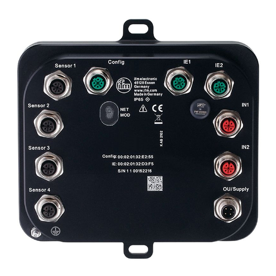
VSE953 Diagnostic electronics 4 Device functions The diagnostic electronics has – 2 analogue inputs – 4 dynamic inputs – 1 analogue or digital output – 1 digital output – 1 TCP/IP parameter setting interface – 2 Modbus TCP ports Input IN1: connection for a pulse signal (HTL). -
Page 7: Function Description
The firmware can only be updated via the VES004 PC software. Only the firmware of the entire device can be updated. w Firmware and operating software → download area www.ifm.com w A description of all firmware parameters and their meaning → VES004 PC software manual. -
Page 8: Mounting
VSE953 Diagnostic electronics 5 Mounting u Disconnect the power to the machine during installation. u Use a flat mounting surface for installation. u Fix the device to the mounting surface using screws (max. M6) and washers. u Ground the device with the earthing screw provided. -
Page 9: Electrical Connection
Diagnostic electronics VSE953 6 Electrical connection The national and international regulations for the installation of electrical equipment must be adhered to. Avoid contact with dangerous contact voltages. u Disconnect power. u Connect the device. u To prevent negative effects on the functions caused by noise voltages, lay sensor cables and load cables separately. -
Page 10: Connection Of The Sensors
VSE953 Diagnostic electronics IN 2 1: 24 V DC (bn) 2: IN 4...20 mA (wh) 3: GND (bu) 4: not used 5: not used OU / Supply M12 connector, A-coded 1: 24 V DC (bn) 2: analogue or digital (wh) -
Page 11: Modbus Tcp
Diagnostic electronics VSE953 7 Modbus TCP 7.1 Properties Requirement Parameter Register access only acyclical r/w Register addressing based on 1 Transmission rate 100 Mbits/s, 10 Mbits/s Protocols Modbus TCP/IP Data format big-endian Modbus TCP/IP Max. input and output process image 1024 bytes (512 registers) - Page 12 VSE953 Diagnostic electronics Input (PLC) Source Type Size Error Word 2 bytes “Error code for object state Hex0000: No fault Hex0001: Internal fault Hex0002: Calculation error Hex0004: Speed out of range Hex0008: Speed not stable Hex0010: Invalid baseline Hex0020: Invalid reference value (1)
- Page 13 Diagnostic electronics VSE953 Input (PLC) Source Type Size Upper/Lower limit monitor <object name> Value Real 4 bytes Object value in SI unit (m/s², m/s, m) Status Byte 1 byte “(Alarm) state of the object 0: OK 1: Warning alarm 2: Damage alarm 3: Inactive 4: Error (description: see Error)”...
-
Page 14: Register
Do self-test Byte 1 byte Do self-test (≠ 0) Set time DINT 4 bytes “Set time, always UTC, format: VSE953: U32: 0x00hhmmss” Set counter ID Byte 1 byte Set ID (1...32) of the counter Set counter value DINT 4 bytes... -
Page 15: Register Mapping Output (Fc3, Fc6 And Fc16)
Illegal data address Code 03 Illegal data value Code 04 Server device failure 7.8 Factory setting VSE953 - Modbus TCP There is read and write access to the device settings. The following default values are set by the factory: Requirement Parameter IP address 192.168.0.100... -
Page 16: Parameter Setting
– Reading the vendor name in the register 39000 is done in the master tool by querying the register "9000" via FC4. – Writing the register 40001 to the VSE953 is done in the master tool by writing to the address "0" via FC6. -
Page 17: Operating And Display Elements
Diagnostic electronics VSE953 8 Operating and display elements For quick identification of error states, the device has two diagnostic LEDs on the device front. LEDs Earthing screw 8.1 Operating states of the network (NET) and mode (MOD) status Designation Meaning Colour State... -
Page 18: Maintenance, Repair And Disposal
VSE953 Diagnostic electronics 9 Maintenance, repair and disposal The operation of the unit is maintenance-free. Only the manufacturer is allowed to repair the unit. u After use dispose of the device in an environmentally friendly way in accordance with the applicable national regulations.
Need help?
Do you have a question about the VSE953 and is the answer not in the manual?
Questions and answers