
Subscribe to Our Youtube Channel
Related Manuals for IFM VSE151


Summary of Contents for IFM VSE151
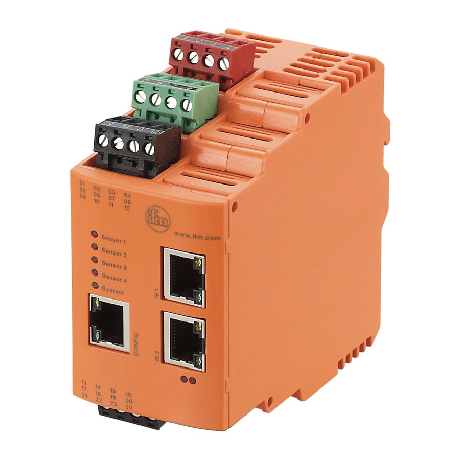
- Page 1 Device manual Diagnostic unit with EtherNet/IP interface for vibration sensors VSE151...
-
Page 2: Table Of Contents
9�1 General factory setting � � � � � � � � � � � � � � � � � � � � � � � � � � � � � � � � � � � � � � � 26 9�2 Factory setting VSE151 - EtherNet/IP � � � � � � � � � � � � � � � � � � � � � � � � � � � 26... -
Page 3: Preliminary Note
12 Maintenance, disposal � � � � � � � � � � � � � � � � � � � � � � � � � � � � � � � � � � � � � � � � � � 29 1 Preliminary note Technical data, approvals, accessories and further information at www�ifm�com� 1.1 Key to the symbols Symbols ►... -
Page 4: Safety Instructions
2 Safety instructions ● Read this document before setting up the product and keep it during the entire service life� ● The product must be suitable for the corresponding applications and environmental conditions without any restrictions� ● Only use the product for its intended purpose (→ Functions and features). ●... -
Page 5: Sensor Functions
5 Sensor functions The diagnostic electronics has – 2 analogue inputs – 4 dynamic inputs – 1 analogue or digital output – 1 digital output – 1 TCP/IP parameter setting interface – 2 EtherNet/IP ports An analogue current signal (0/4…20 mA) or a pulse signal (HTL) can be connected to the analogue inputs�... -
Page 6: 5�1 Firmware
The firmware can only be updated via the VES004 PC software� Only the firmware of the entire device can be updated� Firmware and operating software → download area www.ifm.com A description of all firmware parameters and their meaning → VES004 PC software manual�... -
Page 7: Installation
Up to 32 counters can be configured to measure the duration of exceeding the limit and/or operating times� The signals at the inputs are permanently picked up and continuously monitored according to the set parameters� With objects within the frequency range (imbalance, rolling element bearing ���) the duplex mode is used for monitoring�... -
Page 8: 6�1 Sources Of Interference
Data corruption and loss A minimum distance between the cabling and possible sources of interfe- rence (e�g�, machines, welding equipment, power lines) is defined in the ap- plicable regulations and standards� During system planning and installation, these regulations and standards must be taken into account and observed� Protect the bus cables from sources of electric/magnetic interference and mechanical strain�... -
Page 9: 7�1 Wiring
► To prevent negative effects on the functions caused by noise voltages, lay sensor cables and load cables separately� Maximum length of the sensor cable: 250 m� ► Use a screened sensor cable� The outputs are short-circuit proof and can be configured as either normally closed or normally open�... -
Page 10: 7�2 Connection Of The Sensors
Terminal 1 supply L+ When using an IEPE input 24 V DC + 20% (Integrated Electronics Piezo Electric) The ground GND of the DC supply is directly connected with the ground GND of the sensor supply� Therefore the SELV criteria have to be met for the DC supply�... -
Page 11: Ethernet
8 EtherNet/IP 8.1 EtherNet/IP object classes, messages and services The device supports the Common Industrial Protocol (CIP) according to the ODVA specification V3�20� EtherNet/IP™ uses the Common Industrial Protocol as the application layer� IP and TCP or UDP are used for the network and transport layers�... - Page 12 Warning Real 4 bytes Limits - warning alarm (relative) alarm Damage Real 4 bytes Limits - damage alarm (relative) alarm Base line Real 4 bytes Limits - base line in SI unit (m/s², m/s) Frequency domain <object name> Value Real 4 bytes Object value in SI unit (m/s², m/s, m) State...
- Page 13 Error Word 2 bytes Error code for object state Hex0000: no error Hex0001: internal error Hex0002: calculation error Hex0004: speed out of range Hex0008: speed unstable Hex0010: invalid base line Hex0020: invalid reference value (1) Hex0040: invalid reference value (2) Hex0100: deactivated by signal weighting Hex0200: reference value out of range Hex1000: warning alarm...
-
Page 14: 8�3 Supported Communication Types
Do self-test (≠ 0) Set time, always UTC, format: Set time DINT 4 bytes - VSE150: U32: 0x00ssmmhh - VSE151: U32: 0x00hhmmss - VSE152: U32: 0x00hhmmss - VSE153: U32: 0x00hhmmss Set counter ID Byte 1 byte Set ID (1���32) of the counter... -
Page 15: 8�4�1 Identity Object (Class Code 0X01)
(Address conflict detection) Bit 11 - n�a� (Default Value = 0) Bit 12���15 n�a� (Default Value = 0) Serial number UDINT Defined in the product process Product name STRING VSE151 Common services Service code Class Instance Service name 0x01 Get_Attribute_All... -
Page 16: 8�4�2 Message Router Object (Class Code 0X02)
8.4.2 Message router object (class code 0x02) The message router object provides a messaging connection point through which an EtherNet/IP client may address a service to any object class or instance� The device does not support any access to object attributes� 8.4.3 Assembly object (class code 0x04) The Assembly Object combines attributes of several objects to allow data to be sent to or received from each object via one connection�... -
Page 17: 8�4�5 Device Level Ring Object (Class Code 0X47)
8.4.5 Device level ring object (class code 0x47) The device level ring object (DLR) is the interface for configuration and status information for the DLR protocol� Class attributes Attribute Name Access Data type Value Revision UINT Instance attributes Attribute Name Access Data type Value/description... -
Page 18: 8�4�6 Quality Of Service Object (Class Code 0X48)
8.4.6 Quality of service object (class code 0x48) Quality of service (QoS) affects the forwarding and handling of data streams and results in individual data streams being given differential treatment (usually preferential)� QoS can be used to ensure a transmission bandwidth for separate data flows�... -
Page 19: 8�4�7 Tcp/Ip Object (Class Code 0Xf5)
8.4.7 TCP/IP object (class code 0xF5) The TCP/IP interface object makes it is possible to configure the physical network interface� This includes, for example, the IP address, subnet mask and gateway address� Class attributes Attribute Name Access Data type Value Revision UINT Instance attributes... - Page 20 Attribute Name Access Data type Value/description Physical link object STRUCT of Path to Physical link object – Path size – UINT Size of Path – Path – Padded Logical segments identifying the physical link object EPATH Interface configuration Get, Set STRUCT of: TCP/IP Network Interface configuration –...
-
Page 21: 8�4�8 Ethernet Link Object (Class Code 0Xf6)
Common services Service code Class Instance Service name 0x01 Get_Attribute_All 0x0E Get_Attribute_Single 0x10 Set_Attribute_Single 8.4.8 Ethernet link object (class code 0xF6) The Ethernet link object contains specific status information of the Ethernet interface (IEEE 802�3)� Class attributes Attribute Name Access Data type Value Revision... - Page 22 Attribute Name Access Data type Value/description Media counters Structure of Media specific counters� 12 UINTs "THE CIP NETWORKS LIBRARY Volume 2 EtherNet/IP Adaptation of CIP" Interface control Get, Set Structure of Interface Control Bits WORD Bit 0 - Auto negotiation (0 = active;...
-
Page 23: 8�5 Ethernet/Ip - Assembly Instances
0���254 Output Assembly 255Bytes 8.6 EtherNet/IP - connection types EtherNet/IP - connection types Connection type Is suported by VSE151 Description Exclusive Owner Connections can be configured as multicast or as point-to-point connection in target or originator direction from the scanner�... -
Page 24: 8�6�1 Ethernet/Ip - Defined Connections In The Standard Eds File
8.6.1 EtherNet/IP - defined connections in the Standard EDS File EtherNet/IP - connection types Connection Connection type Input Output Description Assembly assembly Exclusive Owner Connection with 16 byte input and 16 byte output data Exlusive Owner Connection with 32 byte input and 32 byte output data Exlusive Owner Connection with 64 byte input... -
Page 25: 8�7�1 Quality Of Service (Qos)
8.7.1 Quality of Service (QoS) Requirement Parameter Quality of Service Description Quality of service (QoS) affects the forwarding and handling of data streams and results in individual data streams being given differential treatment (usually preferential)� QoS can be used to ensure a transmission bandwidth for separate data flows�... -
Page 26: 8�9 Behaviour If Parameter Set Is Changed
TCP/IP port 3321 Subnet mask 255�255�255�0 Default gateway 192�168�0�244 MAC address Defined in the product process 9.2 Factory setting VSE151 - EtherNet/IP Requirement Parameter IP address No IP address assigned Subnet mask No subnet mask assigned Default gateway No default gateway address assigned... -
Page 27: Parameter Setting
Assignment of the IP address via parameter setting tool VES004 A static IP address can be assigned to the device via the parameter setting tool VES004� 10 Parameter setting The device parameters are set exclusively via the VES004 PC software� All parameters of the configured application are bundled in a parameter set and transferred to the device�... -
Page 28: 11�1 Sensor Operating States
11.1 Sensor operating states LED 1 for sensor 1... LED 4 for sensor 4 Green on Sensor connected and configured Green flashing Sensor is configured; VSA type: sensor is not connected or faulty IEPE type: sensor not connected Yellow on Pre-alarm Red on Main alarm... -
Page 29: 11�4 Led Test When Device Is Switched On
Description Description Colour Status Description MOD (LED 7) EtherNet/IP n�a� Device is switched off status (no voltage supply) green Device functions reliably (normal operation) green flashing The device is not configured (approx� 2 Hz) An unrecoverable error has occurred flashing A recoverable error has occurred orange flashing...
Need help?
Do you have a question about the VSE151 and is the answer not in the manual?
Questions and answers