IFM VSE150 Device Manual
Diagnostic electronics with profinet-io interface for vibration sensors
Hide thumbs
Also See for VSE150:
- Installation instructions (5 pages) ,
- Operating instructions manual (24 pages)

Subscribe to Our Youtube Channel
Related Manuals for IFM VSE150


Summary of Contents for IFM VSE150
- Page 1 Device manual Diagnostic electronics with PROFINET-IO interface for vibration sensors VSE150...
-
Page 2: Table Of Contents
Contents 1 Preliminary note � � � � � � � � � � � � � � � � � � � � � � � � � � � � � � � � � � � � � � � � � � � � � � � � � 4 1�1 Explanation of symbols �... -
Page 4: Preliminary Note
1 Preliminary note Technical data, approvals, accessories and further information at www�ifm�com� 1.1 Explanation of symbols Symbols ► Instruction > Reaction, result […] Designation of keys, buttons or indications → Cross-reference Important note Non-compliance may result in malfunction or interference�... -
Page 5: Documentation
● For DC units the external 24 V DC supply must be generated and supplied according to the requirements for safe extra-low voltage (SELV) since this voltage is provided near the operating elements and at the terminals for the supply of sensors without further protection measures� 3 Documentation This documentation relates to the hardware and firmware status at the time of editing this manual�... -
Page 6: 5�1 Firmware
The device is not approved for safety-related tasks in the field of operator protection� 5.1 Firmware ► Install the firmware to use all device functions� Firmware and operating software → download area www.ifm.com A description of all firmware parameters and their meaning → VES004 PC software manual�... -
Page 7: 5�2 Function Description
5.2 Function description With the device – vibration monitoring (total vibration to ISO) – condition monitoring (condition-based monitoring on the basis of vibration characteristics) – machine protection/process monitoring (monitoring vibration characteristics in real time with a very fast reaction time up to 1 ms) can be implemented�... -
Page 8: Installation
6 Installation ► Mount the unit in a control cabinet with a protection rating of at least IP 54 to ensure protection against accidental contact with dangerous contact voltages and against atmospheric influence� The control cabinet should be installed in accordance with local and national rules and regulations�... -
Page 9: 6�3 Installation Instructions
6.3 Installation instructions Electrostatic discharge The device contains components that can be damaged or destroyed by electrostatic discharge� ► When handling the device, observe the necessary safety precautions against electrostatic discharge (ESD) according to EN 61340-5-1 and IEC 61340-5-1. ► In order to dissipate electrostatic charges, the unit may only be operated on a grounded DIN rail�... -
Page 10: 7�1 Wiring
7.1 Wiring Supply L+ (24 V DC ±20 %) Supply L- (GND) Sensor 4 OU 1: switch/analog OU 2: switch IN 1 (0/4...20 mA / pulse) GND 1 Sensor 3 IN 2 (0/4...20 mA / pulse) GND 2 Sensor 1 Sensor 2 Wiring of the sensors 1...4 (S1...S4) according to the connected unit Sensor... -
Page 11: 7�3 Ethernet Connection
2 m, article no� EC2080 cross-over cable, 5 m, article no� E30112 8 PROFINET IO 8.1 Manufacturer and device information Manufacturer Request Parameter Vendor ifm electronic gmbh Vendor ID 0x0136 Device Name VSE150 Device ID 0x0B00 Order ID... -
Page 12: 8�3 Profinet Io Characteristics
8.3 PROFINET IO characteristics Request Parameter Bit rate 100 Mbits/s Supported protocols SNMP, LLDP, MRP, DCP, DCE-RPC, PTCP, HTTP DAP Module Ident Number 0x00000200 PNIO Version V2�33 Conformance Class Netload Class Maximum Input Length 1024 bytes Maximum Output Length 1024 bytes Maximum Data Length 1024 bytes Physical Slots... - Page 13 Error Word 2 bytes Error code for object state Hex0000: no error Hex0001: internal error Hex0002: calculation error Hex0004: speed out of range Hex0008: speed unstable Hex0010: invalid base line Hex0020: invalid reference value (1) Hex0040: invalid reference value (2) Hex0100: deactivated by signal weighting Hex0200: reference value out of range Hex1000: warning alarm...
- Page 14 Warning Real 4 bytes Limits - warning alarm (relative) alarm Damage Real 4 bytes Limits - damage alarm (relative) alarm Base line Real 4 bytes Limits - base line in SI unit (m/s², m/s, m) Upper/lower limit monitor <object name> Value Real 4 bytes...
-
Page 15: 8�5 Profinet Io Functions
Byte 1 byte Do self-test (≠ 0) Set time, always UTC, format: Set time DINT 4 bytes - VSE150: U32: 0x00ssmmhh - VSE151: U32: 0x00hhmmss - VSE152: U32: 0x00hhmmss - VSE153: U32: 0x00hhmmss Set counter ID Byte 1 byte Set ID (1...32) of the counter... -
Page 16: 8�5�2 Shared Device
Access / data type Default values MANUFACTURER_ID Read / 2 bytes 0x136 ORDER_ID Read / 20 bytes VSE150 SERIAL_NUMBER Read / 16 bytes Defined in the product process HARDWARE_REVISION Read / 2 bytes Corresponds to the hardware revision of the device... -
Page 17: 8�5�3 Reset To Factory
8.5.3 Reset to factory The device supports the Reset to factory function� This function supports the reset (factory setting) of the following parameters of the PROFNET IO device by the PROFINET IO controller� Request Parameter Reset to factory Reset data –... -
Page 18: 8�6�4 Dcp - Discovery And Configuration Protocol
8.6.4 DCP - Discovery and Configuration Protocol Request Parameter Description Discovery and Configuration Protocol DCP distributes the addresses and names of the individual participants in a PROFINET IO system� DCP allows, for example, to assign the IP addresses by means of the symbolic name� 8.6.5 DCE/RPC –... -
Page 19: Delivery Status / Factory Settings
No IP address assigned Subnet mask No subnet mask assigned Default gateway No default gateway assigned Device designation VSE150 Device ID 0x0B00 MAC address Defined in the product process 10 Parameter setting The device parameters are set exclusively via the VES004 PC software� All parameters of the configured application are bundled in a parameter set and transferred to the device�... -
Page 20: Operating And Display Elements
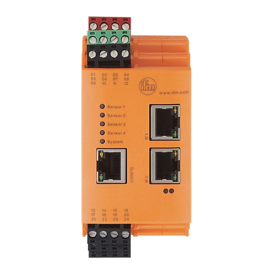
12 Operating and display elements LED 1 LED 2 LED 3 LED 4 LED 5 LED 7 LED 6 1: Config: TCP/IP, IP address 192.168.0.1 (factory setting), parameter setting and data interface (e.g. VES004) 2: IE 1: PROFINET IO 3: IE 2: PROFINET IO LED 1 for sensor 1... -
Page 21: Maintenance, Disposal
LED 6 bus error (BF) and LED 7 status error (SF) LED 6 (BF) LED 7 (SF) Description Parameter set and PROFINET IO settings must be written Green on A PROFINET controller has established an active connection to the PROFINET IO device Orange on Orange on Firmware image is loaded to the RAM via VES004...
Need help?
Do you have a question about the VSE150 and is the answer not in the manual?
Questions and answers