
Related Manuals for IFM VSE153


Summary of Contents for IFM VSE153
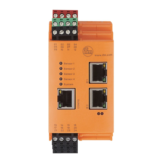
- Page 1 Device manual Diagnostic electronics with Modbus TCP interface for vibration sensors VSE153...
-
Page 2: Table Of Contents
9�1 General factory setting � � � � � � � � � � � � � � � � � � � � � � � � � � � � � � � � � � � � � � � 16 9�2 Factory setting VSE153 - Modbus TCP � � � � � � � � � � � � � � � � � � � � � � � � � � 16 10 Parameter setting �... -
Page 4: Preliminary Note
1 Preliminary note Technical data, approvals, accessories and further information at www�ifm�com� 1.1 Symbols used Symbols ► Instruction > Reaction, result […] Designation of keys, buttons or indications → Cross-reference Important note Non-compliance may result in malfunction or interference� Information... -
Page 5: Documentation
● For DC units the external 24 V DC supply must be generated and supplied according to the requirements for safe extra-low voltage (SELV) since this voltage is provided near the operating elements and at the terminals for the supply of sensors without further protection measures� 3 Documentation This documentation relates to the hardware and firmware status at the time of editing this manual�... -
Page 6: 5�1 Firmware
The dynamic inputs can be used for – vibration monitoring – vibration diagnostics – analysis of other dynamic signals Alternatively, the dynamic inputs can also be used like an analogue input with an analogue current signal (4���20 mA)� The hardware outputs can be configured as 2 x binary (NO/NC) or as 1 x analogue (0/4…20 mA) and 1 x binary (NO/NC)�... -
Page 7: 5�2 Functional Overview
Firmware and operating software → download area www.ifm.com A description of all firmware parameters and their meaning → VES004 PC software manual� 5.2 Functional overview With the device – vibration monitoring (total vibration to ISO) – condition monitoring (condition-based monitoring on the basis of vibration characteristics) –... -
Page 8: Installation
Data (e�g� measured values, alarm states, limits, rotational speeds, timer readings, ���) is exchanged between the diagnostic electronics and the Modbus TCP client/ master (e�g� PLC)� 6 Installation ► Mount the unit in a control cabinet with a protection rating of at least IP 54 to ensure protection against accidental contact with dangerous contact voltages and against atmospheric influence�... -
Page 9: 6�2 Cable Routing In Control Cabinets
6.2 Cable routing in control cabinets ► Install network/bus cables in separate cable ducts or separate cable bundles� ► Where possible, do not install network/bus cables parallel to power supply lines� ► Install network/bus cables at least 10 cm away from power lines� 6.3 Installation instructions Electrostatic discharge The device contains components that can be damaged or destroyed by... -
Page 10: 7�1 Wiring
7.1 Wiring Supply L+ (24 V DC ±20 %) Supply L- (GND) Sensor 4 OU 1: switch/analog OU 2: switch IN 1 (0/4...20 mA / pulse) GND 1 Sensor 3 IN 2 (0/4...20 mA / pulse) GND 2 Sensor 1 Sensor 2 Wiring of 1���4 (S1���S4) according to the use of the sensors Sensor... -
Page 11: 7�3 Ethernet Connection
If the DC circuit is to be grounded (e�g� due to national regulations), the PELV criteria must be adhered to (protective extra-low voltage, circuit electrically isolated from other circuits)� Sensor and diagnostic electronics supply are not electrically isolated� 7.3 Ethernet connection The RJ45 config socket is used for the connection to the Ethernet�... -
Page 12: 8�2 Modbus Tcp Data Model
8.2 Modbus TCP data model Input (PLC) Source Type Size Analogue inputs (DC) <input name> Real 4 bytes Value of the signal connected to the analogue input (IN1, IN2) External inputs <input name> Real 4 bytes Value of the external input (External_xx) Objects Time domain <object name>... - Page 13 State Byte 1 byte (Alarm) state of the object 0: OK 1: warning alarm 2: damage alarm 3: inactive 4: error (description: see Error) Error Word 2 bytes Error code for object state Hex0000: no error Hex0001: internal error Hex0002: calculation error Hex0004: speed out of range Hex0008: speed unstable Hex0010: invalid base line...
- Page 14 Rotational Real 4 bytes Trigger - rotational speed speed Reference Real 4 bytes Trigger - reference value value Warning Real 4 bytes Limits - warning alarm (relative) alarm Damage Real 4 bytes Limits - damage alarm (relative) alarm Counter <counter name> DINT 4 bytes Counter value (in seconds)
-
Page 15: 8�3 Register
DINT 4 bytes Set time, always UTC, format: - VSE150: U32: 0x00ssmmhh - VSE151: U32: 0x00hhmmss - VSE152: U32: 0x00hhmmss - VSE153: U32: 0x00hhmmss Set counter ID Byte 1 byte Set ID (1���32) of the counter Set counter value DINT... -
Page 16: 8�7 Modbus Tcp Output Function Code
Code 6 (dec) write single holding register Code 16 (dec) write multiple holding register 8.8 Modbus TCP exception response The following exception codes are supported by VSE153 Function code Name Code 01 Illegal function Code 02 Illegal data address... -
Page 17: Parameter Setting
10 Parameter setting The device parameters are set exclusively via the VES004 PC software� All parameters of the configured application are bundled in a parameter set and transferred to the device� For a detailed description of all parameters and possible configurations we refer you to the VES004 software manual�... -
Page 18: 11�1 Sensor Operating States
Yellow/red flashing alternately no parameter set loaded 11.2 Operating states for the status LEDs on the industrial Ethernet ports 1 and 2 VSE153 has two industrial Ethernet ports (RJ45 sockets) with one integrated link and activity LED each� Designation Colour... -
Page 19: Maintenance, Disposal
Designation Description Colour Status Description MOD (LED 7) Modbus TCP/IP n�a� device is switched off status (no voltage supply) green device functions reliably (normal operation) device error orange flashing firmware image is loaded to the orange firmware image is written to the flash green flashing 2 s...
Need help?
Do you have a question about the VSE153 and is the answer not in the manual?
Questions and answers