Table of Contents
Advertisement
Quick Links
STSW-IDS002V1: GUI for for STEVAL-ISV021V1, STDES-IDS002V1 and
Introduction
This document describes the software graphic user interface designed to test the key features of the SPV1050 ultra low power
energy harvester and battery charger device.
It can be downloaded directly from www.st.com and supports the following demonstration kit and evaluation boards:
STEVAL-ISV021V1: Energy harvesting demonstration kit based on SPV1050
STDES-IDS002V1: SPIDEr™ Autonomous wireless multi-sensor node powered by PV cells and based on SPV1050
STDES-IDS003V1: SPIDEr™ Autonomous wireless multi-sensor node powered by TEG and based on SPV1050
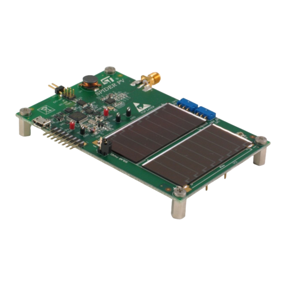
The pictures of evaluation boards listed above and of STDES- ERH001D (power monitoring board, PMB) are shown in
Figure 1. STDES-ERH003V1 (SPIDEr@ST™ with PV module): top and
with TEG): top and
bottom,
Figure 3. STEVAL-ISV021V1 (Energy harvesting module): top and bottom
ERH001D (power monitoring board, PMB): top and
Please refer to the related databriefs for further details.
The dedicated software GUI (STSW-IDS002V1) displays in a very user-friendly way the
performances to let users test the device in the real operating working condition.
The PMB has to be connected to the above mentioned boards in order to provide the electrical specification of energy
harvesting sources (PV module or TEG) and the power extracted from it, the battery operating voltage and current, the
conversion efficiency, the MPPT accuracy, the environmental irradiance or temperature, and the overall system power budget.
The next section describes the hardware setup and software configuration to perform measures and tests.
UM1752 - Rev 3 - March 2019
For further information contact your local STMicroelectronics sales office.
Table 1.
Evaluation products supported by the software
bottom.
STDES-IDS003V1 evaluation boards
bottom,
Figure 2. STDES-ERH001V1 (SPIDEr@ST™
SPV1050
features and system
UM1752
User manual
and
Figure 4. STDES-
www.st.com
Advertisement
Table of Contents

Subscribe to Our Youtube Channel
Related Manuals for ST STSW-IDS002V1


Summary of Contents for ST STSW-IDS002V1
- Page 1 This document describes the software graphic user interface designed to test the key features of the SPV1050 ultra low power energy harvester and battery charger device. It can be downloaded directly from www.st.com and supports the following demonstration kit and evaluation boards: Table 1.
-
Page 2: Evaluation Board Photos
UM1752 Evaluation board photos Figure 1. STDES-ERH003V1 (SPIDEr@ST™ with PV module): top and bottom Figure 2. STDES-ERH001V1 (SPIDEr@ST™ with TEG): top and bottom Figure 3. STEVAL-ISV021V1 (Energy harvesting module): top and bottom UM1752 - Rev 3 page 2/23... -
Page 3: Figure 4. Stdes- Erh001D (Power Monitoring Board, Pmb): Top And Bottom
UM1752 Figure 4. STDES- ERH001D (power monitoring board, PMB): top and bottom UM1752 - Rev 3 page 3/23... -
Page 4: Hardware Setup
UM1752 Hardware setup Hardware setup STEVAL-ISV021V1 Connect the PMB through the USB cable to the PC first and then connect the STEVAL-ISV021V1 to it as shown Figure 5. STEVAL-ISV021V1 and PMB connection. It's strongly recommended to not connect the PMB to the STEVAL-ISV021V1 if it is not yet powered by the USB cable as its current draining could damage the battery on the board. -
Page 5: Stdes-Ids002V1
UM1752 STDES-IDS002V1 Figure 6. Jumpers positioning on bottom side of STEVAL-ISV021V1 STDES-IDS002V1 Connect the PMB through the USB cable to the PC first and then connect the STDES-ERH003V1 to it as shown Figure 7. STDES-ERH003V1 and STDES-ERH001D connection. It's strongly recommended to not connect the PMB to the STDES-ERH003V1 if it is not yet powered by the USB cable as its current draining could damage the battery on the board. -
Page 6: Stdes-Ids003V1
UM1752 STDES-IDS003V1 Check jumper position on bottom side of the STEVAL-IDS002V1. In order to supply the system by the on board PV panel, close pins 2-3 of J7 and leave J4 open. When STDES-ERH003V1 is connected to PMB, the jumpers J5 and J6 must be left open, as shown in Figure 8. -
Page 7: Heater Board
UM1752 Heater board Figure 9. STDES-ERH001V1 and STDES-ERH001D connection Check jumper position on top side of the STDES-ERH001V1. In order to supply the system by the on board TEG, close pins 2-3 of J7 and leave J4 open. When the STDES-ERH001V1 is connected to the PMB, the jumpers J5 and J6 must be left open, as shown in Figure 10. -
Page 8: Figure 11. Peltier Cell Heating Surface And Bottom View Of The Stdes-Erh001V1 With Exposed Teg Plate Surface
UM1752 Heater board order to heat up the exposed surface of the TEG, the Peltier cell based heating module can be used. The module is not included in the box, but it represents a very immediate tool to quickly warm up the accessible plate of TEG. It is supplied through its USB cable which has to be connected to a PC. -
Page 9: Stsw-Isv002V1 Set-Up
Efficiency measurement and MPPT accuracy calculation using the STDES- ERH003V1 or the STEVAL-ISV021V1 Once the STDES-ERH003V1 or the STEVAL-ISV021V1 hardware setup is completed and the STSW-IDS002V1 GUI file runs, the following actions has to be taken: Select the “Efficiency Tab”... -
Page 10: Efficiency Measurement Using The Stdes-Erh001V1
Figure 13. Power visualization tab Efficiency measurement using the STDES-ERH001V1 Once the STDES-ERH001V1 hardware setup is completed and the STSW-IDS002V1 runs, the following actions has to be taken: Select the “Efficiency tab” Click on “Connect” button in PMB panel (highlighted by “1” in Figure 14. -
Page 11: Figure 14. Efficiency Tab: Teg Module Curve With Efficiency And Mppt Data
UM1752 Select “Thermal Efficiency” in the drop-down box in the bottom right side (highlighted by “2” in Figure 14. Efficiency tab: TEG module curve with efficiency and MPPT data) Click on “VOC Calc” button (highlighted by 3 in Figure 14. Efficiency tab: TEG module curve with efficiency and MPPT data) After 20 seconds, efficiency conversion and system power budget will be displayed in the right side table... - Page 12 UM1752 • On channel 2 the V and I profiles of the battery are plotted as a function of time • On channel 3 the output V and I profiles of the temperature sensors are plotted as a function of the time. UM1752 - Rev 3 page 12/23...
-
Page 13: Wireless Sensor Node Configuration And Data Transmission
UM1752 Wireless sensor node configuration and data transmission This section describes the configuration of the STDES-IDS002V1 and STDES-IDS003V1 (SPIDEr@ST), how to perform the data reading of environmental sensors and the transmission of data through wireless interface. By default, only the temperature sensor and the air pressure sensor are enabled, and related data are transmitted every 20 seconds. -
Page 14: Figure 16. Micro Usb Connector
UM1752 Select a pre-loaded configuration (sensor type: accelerometer, temperature, pressure and transmission period) (highlighted by 2 in Figure 16. Micro USB connector) Click on “Write” button (highlighted by 3 in Figure 16. Micro USB connector) Click “Disconnect” on "SPIDEr TX" board panel (highlighted by 1 in Figure 16. -
Page 15: Reading Data
Once connected the receiver the following steps must be followed (refer to Figure 21. Data Visualization tab): Launch the STSW-IDS002V1 and click on “Data Visualization” tab Disconnect the PMB board or the transmitter board Click on “Read Radio Data” button... -
Page 16: Overall System Efficiency And Power Budget
Figure 18. STDES- ERH003V1, LDO2 Switch: ENABLED (left) and DISABLED (right)): Step 1. Launch the STSW-IDS002V1 and select the “Power Visualization” tab Step 2. Disconnect the transmitter board if previously connected, and then click on “Connect” button of PMB panel Step 3. -
Page 17: Figure 22. Power Visualization Tab
UM1752 Figure 22. Power Visualization tab Finally, it is possible to use the STDES-IDS002V1 and the STDES-IDS003V1 as standalone wireless sensor node and the STEVAL-ISV021V1 as stand-alone battery charger, which means without connecting the PMB. In this case the correct jumper positions are shown in Figure 23. -
Page 18: Figure 23. Jumper Positions For The Stdes-Erh003V1 (Left) And Stdes-Erh001V1 (Right) In Stand-Alone Mode
UM1752 Figure 23. Jumper positions for the STDES-ERH003V1 (left) and STDES-ERH001V1 (right) in stand-alone mode Figure 24. Jumper positions for the STEVAL-ISV021V1 in stand-alone mode UM1752 - Rev 3 page 18/23... -
Page 19: Revision History
UM1752 Revision history Table 2. Document revision history Date Version Changes 29-Apr-2014 Initial release. 20-May-2015 Added: Figure 19 Updating to align the document to the the new boards names: STEVAL-IDS003V1 → STDES-ERH001V1; 04-Mar-2019 Transmitter board → STDES-ERH002V1; Power monitoring board → STDES-ERH001D; STEVAL-IDS002V1 →... -
Page 20: Table Of Contents
UM1752 Contents Contents Evaluation board photos............2 Hardware setup. -
Page 21: List Of Tables
UM1752 List of tables List of tables Table 1. Evaluation products supported by the software ..........1 Table 2. -
Page 22: List Of Figures
Figure 1. STDES-ERH003V1 (SPIDEr@ST™ with PV module): top and bottom ......2 Figure 2. - Page 23 ST’s terms and conditions of sale in place at the time of order acknowledgement. Purchasers are solely responsible for the choice, selection, and use of ST products and ST assumes no liability for application assistance or the design of Purchasers’...
Need help?
Do you have a question about the STSW-IDS002V1 and is the answer not in the manual?
Questions and answers