Table of Contents
Advertisement
Quick Links
User Manual
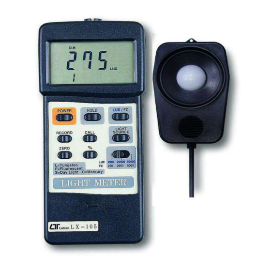
RS PRO LIGHT METER
Stock No: 123-8776
4 light type, zero button, Max., Min.
Your purchase of this LIGHT METER marks a step forward for
you into the field of precision measurement. Although this
LIGHT METER is a complex and delicate instrument, its durable
structure developed. Please read the following instructions
carefully and always keep this manual within easy reach.
OPERATION MANUAL
ENGLISH
Advertisement
Table of Contents

Related Manuals for RS PRO 123-8776


Summary of Contents for RS PRO 123-8776
- Page 1 User Manual RS PRO LIGHT METER ENGLISH Stock No: 123-8776 4 light type, zero button, Max., Min. Your purchase of this LIGHT METER marks a step forward for you into the field of precision measurement. Although this LIGHT METER is a complex and delicate instrument, its durable structure developed.
- Page 2 TABLE OF CONTENTS 1. FEATURES......................2. SPECIFICATIONS....................2-1 General Specifications................2-2 Electrical Specifications.................. 3. FRONT PANEL DESCRIPTION................3-1 Display......................3-2 Power Off/On Button................3-3 Data Hold Button................... 3-4 LUX/FC(Ft-cd) Button..............4 3-5 LCD Contrast Adjust..................3-6 Memory "Record" Button................3-7 Memory "CALL" Button.................. 3-8 Light Source Select Button................
-
Page 3: Specifications
1. FEATURES * Microprocessor circuit ensure high accuracy, and also and also provides special functions and features. * Super large LCD display with contrast adjustment for best viewing angle. * Dual function display. * Heavy duty & compact case. * Records Maximum, Minimum and Average readings. * Data hold. - Page 4 Measurement 0 - 50,000 LUX, 3 ranges. & ranges Foot-candle 0 -5,000 Ft-cd, 3 ranges. Relativity 0 to 1999 %. (Relative to the range selected and the measured value) Sensor The exclusive photo diode & color correction filter, spectrum designed to meet C.
- Page 5 ℃ 2-2 Electrical Specifications (23 5 Measurement Range Max. In-range Display 2,000 Lux 0 - 1,999 Lux 20,000 Lux 1,800 - 19,990 Lux 50,000 Lux 18,000 - 50,000 Lux Ft-cd 0 - 186.0 Ft-cd Foot-candle 2,000 Ft-cd 167 - 1,860 Ft-cd 5,000 Ft-cd 1,670 - 5,000 Ft-cd Range...
-
Page 6: Front Panel Description
3. FRONT PANEL DESCRIPTION Fig. 1 3-1 Display 3-10 % Button (Relativity) 3-2 Power Off/On Button 3-11 Range Switch 3-3 Data Hold Button 3-12 Light Sensor 3-4 LUX/FC(Ft-cd) Button 3-13 Sensor Cover 3-5 LCD Contrast Adjust 3-14 Light Sensor Plug 3-6 Memory "Record"... -
Page 7: Measuring Procedure
4. MEASURING PROCEDURE (1) Push the "Power Off/On Button"(3-2, Fig. 1) to switch the instrument on. (2) Zero Adjust Procedures * Cover the Light Sensor(3-12, Fig, 1) using the Sensor Cover provided (3-13, Fig. 1). * Slide the "Range Switch"(3-11, Fig. 1) to the 2000 LUX position. - Page 8 (6) * On the 20000 LUX range, the last digit will be shown on the lower line of LCD display. * On the 50000 LUX range, the last two digits will show on the lower line of LCD display. * For example : On the 20000 range, if the display show 1562 that means the real display is 15620 LUX.
- Page 9 (9) Data Record( Max., Min., Average reading) The DATA RECORD function displays the maximum, minimum and average readings. To start the DATA RECORD function, press the "Record Button"(3-6, Fig. 1) once. "REC" marker will appear on the LCD display. With the "REC" symbol indicated on the display (a) Push the "CALL Button"(3-7, Fig.
-
Page 10: Additional Features
Optional measuring procedures : DATA HOLD MEMORY RECORD RS232 OUTPUT Max., Min. AVG Power management AUTO POWER OFF MANUAL POWER OFF (Not activated under memory record function during Memory Record Selection) 5. ADDITIONAL FEATURES (a) The instrument has built-in "Auto Power Shut-off" in order to prolong battery life. - Page 11 An RS232 lead with the following connection will be required to link the instrument with the PC serial input. Meter (3.5 mm jack plug) (9W 'D" Connector) Center Pin..........Pin 2 Ground/shield........... Pin 5 The 16 digit data stream will be displayed in the following format : D15 D14 D13 D12 D11 D10 D9 D8 D7 D6 D5 D4 D3 D2 D1 D0 Each digit indicate the following status :...
-
Page 12: Battery Replacement
7. BATTERY REPLACEMENT (1) When the left corner of LCD display show "LBT", it is necessary to replace the battery. However, in-spec measurement may still be made for several hours after low battery indicator appears before the instrument become inaccurate. (2) Slide the Battery Cover(3-17, Fig.
Need help?
Do you have a question about the 123-8776 and is the answer not in the manual?
Questions and answers