Table of Contents
Advertisement
Quick Links
Advertisement
Table of Contents

Subscribe to Our Youtube Channel
Related Manuals for RS PRO 123-8769


Summary of Contents for RS PRO 123-8769
- Page 1 Instruction Manual 123-8769 VOLTAGE/CURRENT CALIBRATOR...
-
Page 2: Table Of Contents
TABLE OF CONTENTS 1. FEATURES............... 1 2. SPECIFICATIONS............ 1 2-1 General Specifications......... 1 2-2 Electrical Specifications........2 3. FRONT PANEL DESCRIPTION........4 3-1 Display..............3-2 Function Switch............3-3 Power Switch............3-4 Range Switch............3-5 Calibration Adjust knob..........3-6 Battery Compartment/Cover........3-7 Input Socket............ -
Page 3: Features
1. FEATURES * Portable instrument for calibrating process devices and measuring process signals. * Adjustable 0-24 mA current source. * Adjustable -199.9 mV to +199.9 mV DCV source. * Current calibrator drives loads up to 500 ohms. * The instruments can power as well as measure a two-wire current loop, useful for testing 4-20mA loop devices ( for example pressure transmitters). -
Page 4: Electrical Specifications
Sampling Approx. 0.4 second. Time Over input Indication of " 1 ". Indication Operating to 50 ( 32 to 122 ℃ ℃ ℉ ℉ Temperature Operating Less than 80% RH. Humidity Power Supply 006P DC 9V, MN1604/PP3 battery or equivalent. Alkaline type or heavy duty type. - Page 5 Current measurement Range Display Accuracy Resolution 0 - 19.99 mA 0.01 mA ± ( 0.25 % FS + 1 d ) 0 - 24 mA 0.1 mA ± ( 0.5 % FS + 1 d ) * FS : full scale Power and current measurement of two wire loop Range Display...
-
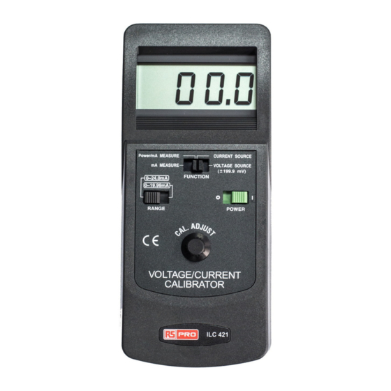
Page 6: Front Panel Description
3. FRONT PANEL DESCRIPTION Fig. 1 3-1 Display 3-2 Function Switch 3-3 Power Switch Symbol 1 = On 0 = Off 3-4 Range Switch 3-5 Calibration Adjust knob 3-6 Battery Compartment/Cover 3-7 Input Socket 3-8 Cable Plug 3-9 Alligator Clips... -
Page 7: Measuring Procedure
4. MEASURING PROCEDURE 4-1 Current source 1) Install the " Cable Plug " ( 3-8, Fig. 1 ) into the " Input Socket " ( 3-7, Fig. 1 ). 2) Slide the " Function Switch " ( 3-2, Fig. 1 ) to the "... -
Page 8: Power And Current Measurement Of Two Wire Loop
Note : The " Red Alligator clip " ( 3-9, Fig. 1 ) is for the positive current measurement input. The " Black Alligator clip " ( 3-9, Fig. 1 ) is for the negative current measurement input. 4-3 Self-powered two-wire current loop measurement meter equivalant block diagram clip DC 12 V... -
Page 9: Dc Mv Source
Note : a. The " Red Alligator clip " ( 3-9, Fig. 1 ) is for the positive current measurement input. The " Black Alligator clip " is for the negative current measurement input. b. The measuring procedures & principal are the same as those in 4-2 Current measurement except the fact that the 12V DC power source is derived from the calibrator rather than from an external voltage source... -
Page 10: Replacement Of Battery
5. REPLACEMENT OF BATTERY 1) When LCD display show the " BAT " marker, It is necessary to replace the battery. However, in-spec measurement may still be made for several hours after low battery indicator appears before the instrument become inaccurate. 2) Slide the "... - Page 11 Africa RS Components SA P.O. Box 12182, Vorna Valley, 1686 20 Indianapolis Street, Kyalami Business Park, Kyalami, Midrand South Africa www.rs-components.com Asia RS Components Ltd Suite 1601, Level 16, Tower 1, Kowloon Commerce Centre, 51 Kwai Cheong Road, Kwai Chung, Hong Kong www.rs-components.com China RS Components Ltd.
Need help?
Do you have a question about the 123-8769 and is the answer not in the manual?
Questions and answers