Table of Contents
Advertisement
Quick Links
Advertisement
Table of Contents

Related Manuals for IFM AE1300


Summary of Contents for IFM AE1300
- Page 1 > > Operating instructions edgeController AE1300 English...
- Page 2 edgeController Contents Preliminary note Legal and copyright information ................... 4 Symbols used ........................5 Warnings used ........................5 Change history ........................5 Safety instructions Electromagnetic compatibility ....................6 Cyber security ........................6 Functions and features Application example ......................8 Mounting Mounting accessories ......................
- Page 3 edgeController 7.1.4 Configuring the Ethernet interfaces .................... 30 7.1.5 Quitting the recovery mode ......................31 Set-up mode ........................32 7.2.1 Starting the set-up mode ......................32 7.2.2 Start application .......................... 33 7.2.3 Show the main set-up menu ....................... 34 7.2.4 Configuring the connections ....................... 35 7.2.5 Creating a data backup ......................
- Page 4 Legal and copyright information 33117 © All rights reserved by ifm electronic gmbh. No part of this manual may be reproduced and used without the consent of ifm electronic gmbh. All product names, pictures, companies or other brands used on our pages are the property of the respective rights owners: •...
- Page 5 edgeController > Symbols used 58277 Important note Non-compliance can result in malfunction or interference Information Supplementary note ► ... Request for action > Reaction, result → ... "see" Cross-reference Decimal number 0x123 Hexadecimal number 0b010 Binary number [...] Designation of pushbuttons, buttons or indications >...
- Page 6 edgeController Safety instructions Content Electromagnetic compatibility ........................6 Cyber security ............................6 61267 • The unit described is a subcomponent for integration into a system. The system architect is responsible for the safety of the system. The system creator undertakes to perform a risk assessment and to create documentation in accordance with legal and normative requirements to be provided to the operator and user of the system.
- Page 7 edgeController • Identification of data sources in the cloud according to a readable name scheme Restricted data flow: • Separation of IT and OT networks using separate network connections • Communication of the software components via standard protocols (Messaging/REST)
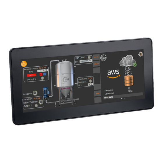
- Page 8 edgeController Functions and features Content Application example ..........................8 61270 The device serves as a gateway between the Operational Technology (OT) and Information Technology (IT) levels. The device is designed for use outside of a control cabinet. It is suited for use at an operating altitude of 3000 m above sea level even under severe conditions, such as an extended temperature range and mechanical stress, see (→...
- Page 9 • EC0733, installation kit for panel mounting • EC1410...EC1414, RAM® mount system for surface mounting You can find more information about the available accessories at: → www.ifm.com > General installation instructions 61273 The following applies to all types of mounting: The responsibility for the compliance with the requirements concerning mounting of the device in the application lies with the system architect.
- Page 10 edgeController 4.2.1 Location for mounting accessories 61274 The back of the unit has been prepared for fixing the mounting accessories. 38,1 1: 4 x M5 threaded hole for the fixing profiles of the installation kit 2: 4 x M5 threaded hole for RAM ® mount system 3: pressure compensation element NOTICE! The device is equipped with a pressure compensation element.
- Page 11 edgeController 4.2.2 Light sensor and status LED 61978 The device is equipped with a light sensor. This sensor is used for automatic brightness adaptation of the display and the operating elements to the ambient brightness. 1: Light sensor 2: Status LED ►...
- Page 12 edgeController > 4.2.3 Device temperature 61276 The internal temperature sensor and the light sensor of the device can be read out with the software. The device primarily heats up due to the following factors: • Solar radiation • Ambient temperature •...
- Page 13 edgeController > Panel mounting / control cabinet installation 61277 > 4.3.1 Safety instructions for panel mounting / control cabinet installation 61278 The specifications for the operating temperature apply in front of and behind the installation surface. The dimensions for the control panel cut-out are a basic prerequisite for the requirements concerning electrical protection, fire protection and protection rating of the device / system.
- Page 14 edgeController CAUTION The use of the installation kit does not ensure the requirements concerning the protection rating of the system with the installed device. > Protection rating and electrical protection might be impaired ► The system creator has to ensure the protection rating depending on the requirements of his application, if necessary by means of external precautions.
- Page 15 edgeController 4.3.3 Panel cutout 61280 ► Make a cut-out. 4 x R5 Panel cutout Tolerances: ± 0.5 mm > 4.3.4 Mounting steps 61281 ► Screw the set screws into the M5 thread on the back of the device. (→ Location for mounting accessories (→...
- Page 16 edgeController Mounting principle 1: M5 hexagon nuts and fixing profiles 2: Panel cutout 3: Damping strips 4: Device with tightened set screws Installation depth A = device depth (approx. 54 mm) Installation depth with the attached connector: approx. 78 mm The fixing profiles and set screws from the installation kit do not protrude from the device.
- Page 17 RAM® mount components 1: Mounting arm with fastening screw 2: Mounting plate with ball head Device with mounted RAM® mount system You will find more information about the available RAM® mount components at: → www.ifm.com > 4.4.1 Mounting steps 61283 ►...
- Page 18 edgeController 38 (1,5") Hole dimensions Tightening torque: 5 ±0.5 Nm ► Slightly loosen the fastening screw of the mounting arm. ► Place the mounting arm onto the ball heads and tighten the fastening screw. > Other installation types 61284 Permissible installation types: •...
- Page 19 edgeController Electrical connection Content General wiring information........................20 Wiring ..............................21 Connection accessories .........................21 Connection technology ...........................21 Operating voltage and circuit breakers ....................22 Shield connection ...........................23 Ethernet interfaces ..........................24 USB interfaces ............................24 61285 ► Disconnect the plant from the mains supply before installation. This also applies to the M12 connectors.
- Page 20 edgeController > General wiring information 61286 Wiring of the connectors (→ Data sheet). Connectors (back of the device) 1: Supply 2: USB0 3: USB1 4: ETH0 (interface for information technology) 5: ETH1 (interface for operational technology) NOTICE! Wrong connection may cause damage to the unit. ►...
- Page 21 114 (VBB+) and pin 120 (VBB-). All other pins must not be used. ► Always connect the pins 119, 121 and 114 of the VBB+ supply together (connection cables of the ifm accessories are correspondingly connected). ► Insulate unused cable ends.
- Page 22 edgeController Only connect the connector when the supply voltage is disconnected. "Hot plugging" is not permitted. "Hot plugging" is permitted at the USB type A connector of the connected M12 adapter. ► Use a min. category 5 (Cat 5) cable for the Ethernet connection. >...
- Page 23 edgeController > Shield connection 61291 To ensure the protection of the device against electrical interference and to ensure the safe function of the device, the housing has to be connected to GND of the supply using the shortest possible route. ►...
- Page 24 This USB interface is connected to a USB connector (art. no.: EC2099). It is used for the connection of USB 2.0 devices. The supply of external USB devices via the USB interface is protected against overload. Max. continuous current: 500 mA USB connection via M12 connector 1: AE1300 2: USB connector 3: USB device, e.g. LTE stick...
- Page 25 edgeController Permanent connection: device – USB connector ► Use a prewired cable. (M12 connector, B-coded on USB socket, type A, watertight, cable length 1.5 m, wires twisted and screened) ► If self-assembling cables, please only use cables according to USB 2.0 specification.
- Page 26 The user can replace the demo application with a user-specific application (→ Programming manual AE1300). > Required documentation 61296 To set up and program the unit, the following documents are required: • Operating instructions AE1300 • Programming manual AE1300 • Data sheet The documents can be downloaded from the internet: → www.ifm.com...
- Page 27 edgeController Settings Content Recovery mode ............................28 Set-up mode ............................32 61297...
- Page 28 edgeController > Recovery mode Content Starting the recovery mode ........................28 Updating the runtime system ........................28 Restoring the data backup........................29 Configuring the Ethernet interfaces ......................30 Quitting the recovery mode ........................31 61299 > 7.1.1 Starting the recovery mode 61300 The user can start the recovery mode via the set-up mode. To start the recovery mode: ►...
- Page 29 Updating the runtime system via USB interface 61302 Requirements: • New runtime system has been downloaded (→ www.ifm.com). • Runtime system file (*.swu) has been unpacked and copied to the USB memory. • USB memory is connected to the unit.
- Page 30 edgeController > 7.1.4 Configuring the Ethernet interfaces 61305 To update the runtime system via a network, the unit must be included in the corresponding Ethernet network. Factory-set IP parameters of the Ethernet interfaces ETH0 and ETH1: → Factory settings (→ p. 44) ►...
- Page 31 edgeController > 7.1.5 Quitting the recovery mode 61308 Requirements: • Recovery mode has been started. ► Click on [RESTART]. > The unit reboots. If an application is stored on the unit: > The application starts automatically. If no application is stored on the unit: >...
-
Page 32: Table Of Contents
edgeController > Set-up mode Content Starting the set-up mode ........................32 Start application ............................33 Show the main set-up menu ........................34 Configuring the connections ........................35 Creating a data backup ..........................36 Configuring the system ...........................37 Displaying the device information ......................42 Removing the USB stick safely ......................42 Leaving the main set-up menu .......................43 Starting the recovery mode ........................43 Rebooting the device ..........................43... -
Page 33: Start Application
edgeController > Notes on operation 61312 > Set-up: access in case of active password protection 61313 If the password protection of the device is activated, the user must enter the correct password to get access to the functions of the set-up menu. Requirements: •... -
Page 34: Show The Main Set-Up Menu
edgeController > 7.2.3 Show the main set-up menu 61315 Requirements: • The device is in the set-up mode. ► Click on [Launch Setup]. > The display shows the main set-up menu: Available options: Symbol / button Description [Connection] Configuring the Ethernet interfaces (→... -
Page 35: Configuring The Connections
edgeController > 7.2.4 Configuring the connections 61316 Requirements: • The main set-up menu is active. ► Click on [Connection]. > The menu page shows the available option: ▪ Configuring the Ethernet interfaces (→ p. 35) ▪ Selecting network services (→ p. 36) >... -
Page 36: Creating A Data Backup
edgeController > Selecting network services 61320 Requirements: • The [Connection] menu page is active. ► Click on [Network Services]. > The menu page shows the available network services. Service Description TELNET Service for non-secure access to the device panel Service for non-secure data transmission SSH/SCP Services for secure access to the device panel and secure data transmission Service for automatic time synchronisation... -
Page 37: Configuring The System
edgeController > When the backup is finished, a message appears to indicate whether the backup was successful. The backup (*.swu) can be restored in recovery mode. → Updating the runtime system (→ p. 28) > 7.2.6 Configuring the system 61322 Requirements: •... - Page 38 edgeController > Setting the system time 61324 Requirements: • The menu page [System Setup] is active. ► [Date and Time] ► Select the [System Time] tab. > The menu page shows the current system time (date, time). > The menu page shows the current time zone. ►...
- Page 39 edgeController > Enabling / disabling password protection 61325 On delivery, the password protection for the setup menu is disabled. If the password protection is enabled after the first setup, the password set at the factory will be valid: pdm3 ► To ensure effective protection, change this password set at the factory! The programming software CODESYS can access the IEC project saved on the device even if password protection is enabled.
- Page 40 edgeController > Changing the password 61326 If the password is forgotten, it is necessary to carry out a recovery update. ► Reinstalling the runtime system of the device (→ Updating the runtime system (→ p. 28)). ► Restoring stored data (→ Updating the runtime system (→...
- Page 41 edgeController > The device loads the selected image file. > The menu page shows the new start image. > Setting the display brightness 61328 Requirements: • The menu page [System Setup] is active. ► [Display Brightness] > The menu page shows the current relative brightness of the screen (in %). ►...
-
Page 42: Displaying The Device Information
edgeController > 7.2.7 Displaying the device information 61331 Requirements: • The main set-up menu is active. ► [Device Info] > Menu page shows the following information: Name Description [Firmware] Firmware version [Serial Number] Serial number of the device [MAC Address] MAC addresses of the Ethernet interfaces [External Voltage (supply clamp 15)] Value of the connected supply voltage on terminal 15 in mV... -
Page 43: Leaving The Main Set-Up Menu
edgeController > 7.2.9 Leaving the main set-up menu 61333 Requirements: • The set-up menu is active (→ Show the main set-up menu (→ p. 34)). ► Click on > The device leaves the set-up main menu. > The screen shows the start page of the set-up mode. >... - Page 44 edgeController Factory settings 61336 Parameter ETH0 (interface to OT level) ETH1 (interface to IT level) IP address 192.168.82.247 192.168.83.247 Network mask 255.255.255.0 255.255.255.0 Gateway address 192.168.82.1 0.0.0.0...
-
Page 45: System Update
edgeController Maintenance, repair and disposal Content System update ............................45 Battery change ............................46 Cleaning the display surface ........................47 Cleaning the housing surface .........................47 Repair ..............................47 Disposal ..............................47 61337 > System update 61338 ► The runtime system update is done in Recovery mode (→... -
Page 46: Battery Change
edgeController > Battery change 61339 The battery may only be changed by a qualified person ► Before changing the battery, fully separate the device from supply voltage. 1: service cover 2: battery ► Replace the battery if the displayed time is permanently wrong after the unit is switched on. NOTICE! The protection rating does not apply if the service cover is open and there is no ESD protection of the accessible contacts inside... -
Page 47: Cleaning The Display Surface
edgeController > Cleaning the display surface 61340 Unsuitable cleaning agents and chemicals may damage the display surface. The following agents are not suited for cleaning the display: • Chemicals dissolving plastics such as methylated spirit, benzine, thinner, alcohol, acetone or ammonia •...
Need help?
Do you have a question about the AE1300 and is the answer not in the manual?
Questions and answers