Table of Contents
Advertisement
Quick Links
Advertisement
Table of Contents

Related Manuals for IFM CabinetLine AE3100


Summary of Contents for IFM CabinetLine AE3100
- Page 1 Operating instructions IIoT controller CabinetLine AE3100...
-
Page 2: Table Of Contents
IoT Core ........ -
Page 3: Preliminary Note
/ packaging or at documentation.ifm.com. 1.1 Legal and copyright information © All rights reserved by ifm electronic gmbh. No part of these instructions may be reproduced and used without the consent of ifm electronic gmbh. All product names, pictures, companies or other brands used are the property of the respective rights owners. -
Page 4: Change History
AE3100 IIoT controller 1.5 Change history Issue Subject Date New creation of the document 04 / 2023... -
Page 5: Safety Instructions
IIoT controller AE3100 2 Safety instructions • The unit described is a subcomponent for integration into a system. – The system architect is responsible for the safety of the system. – The system architect undertakes to perform a risk assessment and to create documentation in accordance with legal and normative requirements to be provided to the operator and user of the system. - Page 6 AE3100 IIoT controller Restricted data flow • Factory separation of IT and OT networks using separate network connections • Communication of the software components via standard protocols (messaging/REST) ATTENTION Device operation in an unprotected network environment. w Unauthorised read or write access to data is possible. w Unauthorised manipulation of the device function is possible.
-
Page 7: Intended Use
IIoT controller AE3100 3 Intended use The device serves as a Programmable Logic Controller (PLC). The device offers special functions and protocols for flexible use in IIoT applications to transmit process data, status and diagnostic information between the automation level or also called operational technology level (OT) and the information technology level (IT). -
Page 8: Items Supplied
AE3100 IIoT controller 4 Items supplied • 1 IIoT controller AE3100 • 1 DIN rail holder incl. 2 self-tapping screws (Torx TX10) • 1 connecting plug for voltage connection... -
Page 9: System Description
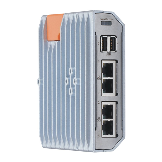
IIoT controller AE3100 5 System description 5.1 Overview 1: Status LEDs 2: USB port usb0 3: USB port usb1 4: Ethernet port eth0 5: Ethernet port eth1 6: Ethernet port eth2 7: Ethernet port eth3 8: Voltage supply 9: Service cover 10: Micro SD card slot 5.2 Ethernet ports The device has 4 Ethernet ports. -
Page 10: Micro Sd Card Slot
Ò Programming manual 5.8 ifm IoT Core The device has the ifm IoT Core. The ifm IoT Core represents the functionality of the device. The functionality consists of a set of data, services and events. The elements of the ifm IoT Core are arranged in a JSON object in a hierarchical tree structure. -
Page 11: Installation
IIoT controller AE3100 6 Installation 6.1 Install device The housing of the device has the following holes: 1: Rear: DIN rail adapter 2: Left side: DIN rail adapter This results in the following options for DIN rail mounting: Upright on horizontal DIN rail Flat on horizontal DIN rail Flat on vertical DIN rail The device may only be mounted and operated on a grounded DIN rail. -
Page 12: Electrical Connection
AE3100 IIoT controller 7 Electrical connection 7.1 General notices The device must be connected by a qualified electrician. u Observe the national and international regulations for the installation of electrical equipment. The device contains components that can be damaged or destroyed by electrostatic discharge. u Please observe the required precautions against electrostatic discharge! 7.2 Ethernet ports (IT level) The device is connected to the IT network level via the ethernet ports eth0 and eth1. -
Page 13: Voltage Supply
IIoT controller AE3100 1 2 3 4 1: +5 V Data + 2: Data - u Connect USB devices with free USB ports. 7.5 Voltage supply The device is connected to the US supply voltage via the voltage connection. Pin 0 V of the voltage connection is directly connected with the metal housing. Pin 0 V of the voltage connection is connected via the DIN rail holder with the DIN rail. -
Page 14: Operating And Display Elements
AE3100 IIoT controller 8 Operating and display elements 8.1 LEDs status: SYS status: APP status: PRG Ethernet: ACT (port eth0) Ethernet: LNK (port eth0) Ethernet: ACT (port eth1) Ethernet: LNK (port eth1) Ethernet: ACT (port eth2) Ethernet: LNK (port eth2) 10: Ethernet: ACT (port eth3) 11: Ethernet: LNK (port eth3) 8.1.1 Status SYS LED... -
Page 15: Function Keys
IIoT controller AE3100 8.2 Function keys The device provides the following function keys: • Boot Recovery Using the boot recovery button, the user can start the device in recovery mode. In recovery mode, various management functions can be performed (e.g. updating the device's firmware). The Boot Recovery button is located on the left side of the device next to the service cover. -
Page 16: Set-Up
The device starts. w The status LEDs show the status of the device. 9.1 Getting started The user can change the IP settings of the Ethernet interfaces of the device with the help of the ifm IoT Core Visualizer. Requirements: ü... -
Page 17: Settings
Start web browser. u Go to the following URL: http://<ip_eth3>:8090/browse (e.g. http:// 192.168.83.247:8090/browse ) w User interface of the ifm IoT Core Visualizer appears. u Select [Update] menu. w Menu page shows information about the current firmware version. u In the [Firmware] area: Click on [Load software file]. - Page 18 AE3100 IIoT controller u Connect the USB memory with a free USB port of the device. u Press and hold the boot recovery button and connect the device to the supply voltage. Keep the boot recovery button pressed until the status LED SYS flashes yellow. w The device starts.
-
Page 19: Troubleshooting
IIoT controller AE3100 11 Troubleshooting 11.1 Status LEDs The status LEDs signal the occurrence of errors and provide information about the cause of the error. 11.2 Resetting IP settings of the Ethernet ports If the IP addresses of the Ethernet ports are lost, the user can reset the IP settings to the factory settings. -
Page 20: Maintenance, Repair And Disposal
AE3100 IIoT controller 12 Maintenance, repair and disposal The device is maintenance-free with the exception of battery replacement. 12.1 Battery change If the time is permanently out of adjustment after the device is turned on, the battery must be changed. Position of the battery: 1: Service cover (orange) 2: Battery ATTENTION... -
Page 21: Repair
IIoT controller AE3100 Micro-fibre cloths without chemical additives are recommended. 12.3 Repair The device must only be repaired by the manufacturer. u Observe the safety instructions. 12.4 Disposal u After use, dispose of the unit in an environmentally friendly way in accordance with the applicable national regulations.
Need help?
Do you have a question about the CabinetLine AE3100 and is the answer not in the manual?
Questions and answers