
Related Manuals for IFM AC1433


Summary of Contents for IFM AC1433
- Page 1 > > Device Manual SmartPLC DataLine with EtherCAT slave interface AC1433 AC1434 Master profile: M4 Firmware: 4.3.1 or higher English...
- Page 2 Preliminary note Legal and copyright information ................... 5 Purpose of the document ..................... 5 Explanation of Symbols ....................... 6 Overview: User documentation for AC1433/34 ..............7 Modification history ......................7 Safety instructions General safety instructions ....................8 Required background knowledge ..................8 Tampering with the unit ......................
- Page 3 5.6.3 Interfaces: EtherCAT interface ....................87 ifm system solutions ......................92 5.7.1 Notes on ifm system solutions ....................93 5.7.2 Show information about installed ifm apps ................. 94 5.7.3 Install single/basic app ....................... 95 5.7.4 Install multi app .......................... 96 5.7.5 Update ifm apps .........................
- Page 4 SmartPLC DataLine with EtherCAT slave interface Appendix Approval tests / certifications ...................115 Technical data ........................116 8.2.1 Housing ............................ 116 8.2.2 Display elements ........................116 8.2.3 Operation ..........................116 8.2.4 Power supply connections ......................116 8.2.5 Interface ........................... 117 8.2.6 Programmable Logic Controller (PLC) ..................117 Address assignment in Ethernet networks ..............118 Configuration interfaces: Connection concepts ...............119 8.4.1...
-
Page 5: Preliminary Note
Legal and copyright information 33117 © All rights reserved by ifm electronic gmbh. No part of this manual may be reproduced and used without the consent of ifm electronic gmbh. All product names, pictures, companies or other brands used on our pages are the property of the respective rights owners: ... -
Page 6: Explanation Of Symbols
SmartPLC DataLine with EtherCAT slave interface > Explanation of Symbols 34171 WARNING! Death or serious irreversible injuries may result. CAUTION! Slight reversible injuries may result. NOTICE! Property damage is to be expected or may result. Important note Non-compliance can result in malfunction or interference Information Supplementary note ►... -
Page 7: Modification History
SmartPLC DataLine with EtherCAT slave interface > Overview: User documentation for AC1433/34 41793 ifm electronic provides the following user documentation for the models of the device class "SmartPLC DataLine mit EtherCAT-Slave-Schnittstelle": Document Content / Description Data sheet Technical data of the device as a table ... -
Page 8: General Safety Instructions
SmartPLC DataLine with EtherCAT slave interface Safety instructions Content General safety instructions ........................8 Required background knowledge ......................8 Tampering with the unit ..........................8 28333 > General safety instructions 41415 Read this document before setting up the product and keep it during the entire service life. Only use the product for its intended purpose. -
Page 9: System Description
SmartPLC DataLine with EtherCAT slave interface System description Content Intended use ............................10 Information concerning the device ......................11 28392... -
Page 10: Intended Use
SmartPLC DataLine with EtherCAT slave interface > Intended use Content Permitted use ............................10 Prohibited use ............................10 36928 > 3.1.1 Permitted use 36762 The device is designed for operation in the control cabinet. The device may only be used for the following purposes: ... -
Page 11: Information Concerning The Device
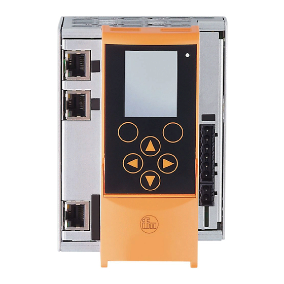
SmartPLC DataLine with EtherCAT slave interface > Information concerning the device Content Overview ..............................11 Operating elements ..........................12 Display elements ............................12 CODESYS PLC ............................12 Interfaces ..............................13 Required accessories ..........................13 36905 > 3.2.1 Overview 36757 Legend: Display Status LED (H1) 2 function keys 4 arrow keys Connector (X1) for AS-i 1, AS-i 2, functional earth... -
Page 12: Operating Elements
Applications that have been created with the IEC 61131-3 compliant programming software "CODESYS Development System" (from version 3.5 SP9 Patch 7 Hotfix 3) System solutions that have been provided by ifm electronic Programmable Logic Controller (PLC) Technical data: →... -
Page 13: Required Accessories
SmartPLC DataLine with EtherCAT slave interface > 3.2.5 Interfaces 36927 The device provides the following interfaces: > Ethernet configuration interfaces 36913 The configuration interface 1 (X3) is behind the front flap of the device. The configuration interface 2 (X8) is underneath the EtherCAT interface (X6/X7). The user can access the following functions via both interfaces: ... - Page 14 SmartPLC DataLine with EtherCAT slave interface Operation Content Control of the graphical user interface ....................14 Menu view...............................16 Page view ...............................19 Remote access ............................32 41713 > Control of the graphical user interface 41568 Below the display is the key panel with six membrane keys. The operator controls the graphical user interface of the device with these keys.
-
Page 15: Function Keys
SmartPLC DataLine with EtherCAT slave interface > 4.1.1 Function keys 41476 The two function keys allow the operator to trigger specified actions (e.g. tick a checkbox). The function of the function keys changes depending on the context. The two text fields in the navigation status bar are associated with the function keys located directly below the display. -
Page 16: Menu View
SmartPLC DataLine with EtherCAT slave interface > Menu view 41755 The menu view allows the user to select the menu page with the required control or display function. Legend: Info bar Main navigation bar Subnavigation bar 1 Subnavigation bar 2 Selected menu item (focus) Navigation status bar with ... -
Page 17: Navigation Aids
SmartPLC DataLine with EtherCAT slave interface > 4.2.2 Navigation aids 41748 The following screen elements help you navigate through the menu: > The info bar shows the navigation path of the selected menu symbol. > The navigation compass shows which navigation steps are possible from the current position. Legend: Info bar Navigation path to the focused menu element:... - Page 18 SmartPLC DataLine with EtherCAT slave interface 6. ► Use [] to select the [Settings] menu symbol. > The focus is on the [Settings] menu symbol. ► Press the [Select] function key to go to the page view of the [Settings] menu item. >...
-
Page 19: Page View
SmartPLC DataLine with EtherCAT slave interface > Page view 41786 The page view allows the user to select and execute a requested function. Legend: Info bar Main navigation bar Page Scroll bar Tab menu Page element with focus Navigation status bar with ... - Page 20 SmartPLC DataLine with EtherCAT slave interface > 4.3.3 Description of the control elements Content Tab menu/Tab ............................21 Button ..............................22 Checkbox ..............................22 List ................................23 Slave selector ............................24 Confirmation message ..........................29 Numerical field ............................30 Binary field ..............................31 41586 A page consists of different control elements.
- Page 21 SmartPLC DataLine with EtherCAT slave interface > Tab menu/Tab 41675 A tab menu groups together the different functions of a menu page. A tab menu consists of at least two tabs. A tab combines related functions. Example: > The focused tab has an orange background >...
- Page 22 SmartPLC DataLine with EtherCAT slave interface > Button 41536 A button allows the operator to carry out a specified action once. The caption on the button describes the action. Example: Use: Select a button ► Use the arrow keys [] / [] to select a button. >...
- Page 23 SmartPLC DataLine with EtherCAT slave interface > List 41484 A list provides a set of defined values. The operator can select precisely one value from this set (= 1 of n selection). Examples: = list without caption = list with caption Use: Select a list ►...
- Page 24 SmartPLC DataLine with EtherCAT slave interface > Slave selector Content Overview of slave states .........................25 Overview of free slave addresses ......................27 41653 The slave selector is used to select an AS-i slave or an AS-i address. Legend: Indicator of AS-i master operating mode AS-i address symbol Highlighted AS-i address (focus) Status message of highlighted AS-i address...
- Page 25 SmartPLC DataLine with EtherCAT slave interface > Overview of slave states 41728 > The slave selector shows an overview of the slaves in the selected AS-i network. > The symbol colour signals the slave status. Meaning of symbols and colours: Slave status: colour code + symbols →...
- Page 26 SmartPLC DataLine with EtherCAT slave interface > Slave status: colour code + symbols 41652 Single slave A/B slave Colour Meaning grey No slave found: slave address is neither in the LPS nor in the LDS green Slave is activated ( in LAS) Configuration error type 1: slave is projected (in LPS) but was not found (in LDS) yellow...
- Page 27 SmartPLC DataLine with EtherCAT slave interface > Overview of free slave addresses 41729 In this overview, the slave selector shows the free and occupied AS-i addresses. > The symbol colour indicates the state of the AS-i address. Meaning of symbols and colours: Free slave addresses: colour code + symbols →...
- Page 28 SmartPLC DataLine with EtherCAT slave interface > Free slave addresses: colour code + symbols 41493 Single slave A/B slave Colour Meaning Prio. grey Slave address is already used. turquoise Address is free according to LDS (= no slave found), however: address already belongs to a stored projection (= application profile).
-
Page 29: Confirmation Message
SmartPLC DataLine with EtherCAT slave interface > Confirmation message 41606 The confirmation message is a security prompt. It appears when important changes are made to the system settings. The confirmation message shows the changes made. For the changes to become effective, they first need to be acknowledged by the operator. - Page 30 SmartPLC DataLine with EtherCAT slave interface > Numerical field 41720 The numerical field allows the operator to enter integer values. The value range is context-specific. Numerical fields are part of the following GUI elements: Control element Example Meaning IP address Entry of an IP address (IPv4) in [w.x.y.z] format ...
- Page 31 SmartPLC DataLine with EtherCAT slave interface Adopt the set values ► Use [Select] function key to confirm the set values and to leave the edit mode. Use [Back] function key to reset the set values and to leave the edit mode. >...
-
Page 32: Remote Access
SmartPLC DataLine with EtherCAT slave interface > Remote access Content General ..............................32 Recommended browsers ........................32 Operating instructions ..........................33 41775 The device has an integrated web server. It generates a web interface which allows remote access to all device functions via an web browser. The web-interface allows the operator to easily configure, parameterise and monitor the device in permanent operation via an ethernet-based network. -
Page 33: Web Interface: Access
SmartPLC DataLine with EtherCAT slave interface > 4.4.3 Operating instructions 41723 > Web interface: Access 41681 ► PC / Laptop / mobile device: Start Internet browser. ► Internet browser: Enter IP address of the device in the address line (e.g. 192.168.82.2) >... -
Page 34: Web Interface Login
the PC/laptop is restarted AC1433/34 is restarted To prevent unauthorised access to the device settings: ► Manually log off before you leave the web interface! (→ Disconnect from web interface (→ S. 35)) ►... - Page 35 SmartPLC DataLine with EtherCAT slave interface > Disconnect from web interface 41457 To log out of the web interface: ► Start web interface > Status line with status message is displayed at the top of the web interface: ► Log out of the web interface by clicking [Logout] >...
-
Page 36: Start Screen
(→ S. 99)). The start screen displays the status information of important system components. The start screen is also the starting point for access to the menu functions of the AC1433/34. AS-i Master 1 operation mode →Operating mode of the AS-i master (→... -
Page 37: Menu Functions
SmartPLC DataLine with EtherCAT slave interface > Menu functions 41739 The main navigation bar of the AC1433/34 provides access to the following menus: Symbol Description Access to the most important device functions →System (→ S. 60) Configuration and diagnostics of the AS-i 1 network (AS-i master, AS-i slaves) →AS-i 1 / AS-i 2... -
Page 38: Quick Setup
SmartPLC DataLine with EtherCAT slave interface > Quick setup 42973 The [Quick-Setup] menu provides fast access to the most important device functions. Navigation path Functions → Quick setup: Project AS-i networks (→ S. 39) → Quick setup: Configure the operating mode of the AS-i masters (→... -
Page 39: Quick Setup: Project As-I Networks
SmartPLC DataLine with EtherCAT slave interface > 5.3.1 Quick setup: Project AS-i networks 41782 During projection adaptation, the AS-i master carries out the following actions: The configuration data of all detected AS-i slaves (LDS) is saved The detected AS-i slaves are added to the list of projected slaves (LPS) During a project a projection adaptation all output parameters of the unconnected AS-i slaves are reset to their default value in the AS-i master (single /A slaves = 0xF, B slaves = 0x7). -
Page 40: Quick Setup: Configure The Operating Mode Of The As-I Masters
SmartPLC DataLine with EtherCAT slave interface > 5.3.2 Quick setup: Configure the operating mode of the AS-i masters 41778 Operating modes of the AS-i Information regarding the operating modes of an AS-i master:→ master (→ S. 122) To configure the operating modes of the AS-i masters: Select the menu page ►... -
Page 41: Quick Setup: Configure The Output Access
SmartPLC DataLine with EtherCAT slave interface > 5.3.3 Quick setup: Configure the output access 41783 Only one control instance at a time can have write access to the outputs of the connected AS-i slaves. The operator configures the control instance with the parameter [Output access]. To configure the control instance of the AS-i slave outputs: Select the menu page ►... - Page 42 SmartPLC DataLine with EtherCAT slave interface Select menu page ► ► Select tab [EtherCAT]. Set the EtherCAT address of the device ► Set the following parameters as required: Parameter Description Possible values [ID] EtherCAT address of the device EtherCAT address 1 65535 EtherCAT address 65535 ►...
- Page 43 SmartPLC DataLine with EtherCAT slave interface > 5.3.6 Quick setup: Set the Configuration interface 1 41781 The device provides the following options for configuration of the Ethernet Configuration interface 1: The operator sets the interface parameters (IP address, network mask, Manual = gateway address) manually.
- Page 44 SmartPLC DataLine with EtherCAT slave interface Configure the IP parameters automatically ► Check [Optain IP address autom]. ► Press [Accept] to save the changes. > The device tries to obtain IP parameters from a DHCP server. > If the IP parameter configuration via DHCP server fails, the device will generate the IP parameters by means of the Zeroconf protocol.
- Page 45 SmartPLC DataLine with EtherCAT slave interface > 5.3.7 Quick setup: Set the configuration interface 2 42159 Configuration interface 2 (X8) has the same configuration options as configuration interface 1 (X3). → Quick setup: Set the Configuration interface 1 (→ S. 43) To configure configuration interface 2 (X8): Select menu page ►...
- Page 46 SmartPLC DataLine with EtherCAT slave interface > 5.3.8 Quick setup: Address the AS-i slaves connected to AS-i Master 1 41764 To change the address of an AS-i slave connected to AS-i Master 1: Select the menu page ► ► Select [Addressing AS-i 1] tab. Select the AS-i slave >...
- Page 47 SmartPLC DataLine with EtherCAT slave interface > 5.3.9 Quick setup: Address the AS-i slaves connected to AS-i Master 2 41763 The procedure for addressing the AS-i slaves connected to AS-i Master 2 is the same as for Quick setup: Address the AS-i slaves addressing the AS-i slaves connected to AS-i Master 1 (→...
- Page 48 SmartPLC DataLine with EtherCAT slave interface > AS-i 1 / AS-i 2 41522 The [AS-i 1] and [AS-i 2] menus provide access to configuration functions of the AS-i networks. The [AS-i 2] menu is only available for devices with two AS-i masters! Navigation path Content AS-i master settings...
- Page 49 SmartPLC DataLine with EtherCAT slave interface > 5.4.1 AS-i 1 / AS-i 2: Master setup 41537 The menu item [Master setup] provides access to the configuration options of the selected AS-i master. > Set the operating mode of the AS-i master 41640 More information on the operating modes of the AS-i master: →...
- Page 50 SmartPLC DataLine with EtherCAT slave interface > Carry out a projection adaptation 41535 During projection adaptation, the AS-i master stores the configuration of all AS-i slaves currently found on the AS-i network in its memory and assigns a valid AS-i address to each of them. The projection adaptation can only be carried out in projection mode: ►...
- Page 51 SmartPLC DataLine with EtherCAT slave interface > Set the monitoring functions of the AS-i master 41641 To set the monitoring functions of the selected AS-i master: Select the menu page > > ► Set the monitoring functions of the AS-i master ►...
- Page 52 SmartPLC DataLine with EtherCAT slave interface > 5.4.2 AS-i 1 / AS-i 2: Diagnosis 41538 The [Diagnosis] menu provides access to the diagnostic data of the selected AS-i network. > Display and reset the error counters 41445 To display and reset the AS-i error counters: Select the menu page ►...
- Page 53 SmartPLC DataLine with EtherCAT slave interface > Display the voltage supply analysis 41502 To display the voltage supply analysis: Select the menu page ► > > ► Select [Power supply] tab. Display the voltage supply analysis > Page shows the following information: Name Description Possible values...
- Page 54 SmartPLC DataLine with EtherCAT slave interface > 5.4.3 AS-i 1 / AS-i 2: AS-i slaves 41539 The [AS-i Slaves] menu provides access to information and configuration options of the AS-i slaves. The scope of configuration options shown ([Data] and [Setup] tab) varies according to the status of the selected AS-i slaves.
-
Page 55: Digital Output
SmartPLC DataLine with EtherCAT slave interface Digital output 41465 Designation Description Example / Possible values [Outputs] Current values of the digital outputs (binary and hexadecimal representation) Data bit is switched off (0 / OFF) Data bit is switched on (1 / ON) ... - Page 56 SmartPLC DataLine with EtherCAT slave interface > Change the digital output values manually 41602 WARNING! The manual change of digital output values may cause undesired consequences to the control process. > Risk of personal injury! > Risk of material damage to the machine/plant! The operator is responsible for any consequences caused by the manual change of the digital ouput values! ►...
- Page 57 SmartPLC DataLine with EtherCAT slave interface > Change the analogue output values manually 41598 To change the analogue output values of an AS-i slave manually: Enable manual access to the outputs ► Set [Output access] parameter = Manual (→Set the output access (→...
- Page 58 SmartPLC DataLine with EtherCAT slave interface > Change an AS-i slave address 41534 To change the address of an AS-i slave: Select the menu page ► > > ► Select an AS-i slave (→Slave selector (→ S. 24)). ► Select [Setup] tab. Change the address of the AS-i slave ►...
- Page 59 SmartPLC DataLine with EtherCAT slave interface > Change the Extended ID1 of the AS-i slave 41601 To set the Extended ID1 of an AS-i slave: Select the menu page > > ► ► Select an AS-i slave (→Slave selector (→ S. 24)). ►...
- Page 60 SmartPLC DataLine with EtherCAT slave interface > System 41700 The [System] menu provides access to functions that allow configuration of the system and the device-internal PLC. Navigation path Functions Device-internal PLC →System: Programmable Logic Controller (PLC) (→ S. 61) > System information →Show version information (→...
-
Page 61: System: Programmable Logic Controller (Plc)
Show target visualisation (→ S. 65) PLC diagnosis Show memory used → (→ S. 66) > > For information about the programming of the device-internal PLC with CODESYS, please refer to the programming manual: → www.ifm.com > product page > [Downloads]... -
Page 62: Plc: Information
SmartPLC DataLine with EtherCAT slave interface > PLC: Information 41796 The [Information] menu item provides access to the PLC status and project information. > Display the status of the CODESYS PLC 41467 To display information about the current status of the device-internal PLC: Select the menu page ►... -
Page 63: Plc: Settings
SmartPLC DataLine with EtherCAT slave interface > PLC: Settings 41801 The [Settings] menu item provides access to the PLC applications (apps) on the device. > Control a single PLC application 41576 [App x/y] – x ... number of the app displayed –... - Page 64 SmartPLC DataLine with EtherCAT slave interface > Control PLC applications 41577 To control all PLC applications stored on the device: Select the menu page > > ► ► Select [All applications] tab. Display status information about the PLC applications > Page shows the following information: Designation Meaning...
- Page 65 Using the CODESYS programming system, the user can optionally program a target visualisation to create an application-specific user interface for the display of AC1433/34. The target visualisation is loaded onto the device together with the CODESYS project, but it must be activated manually.
-
Page 66: Plc: Diagnosis
SmartPLC DataLine with EtherCAT slave interface > PLC: Diagnosis 41797 The [Diagnosis] menu item provides access to diagnostic data of the device-internal PLC. > Show memory used 41663 To display information about the memory capacity currently used: Select the menu page ►... -
Page 67: System Information
Show version information > Page shows the following information: Name Description Possible values [Modell] Article number of the device e.g. AC1433/34 [SN] Serial number of the device e.g. 000000113034 [Build] Version number of the installed firmware e.g. 4.3.1 [HW version] Version number of the device main board e.g. -
Page 68: System Setup
SmartPLC DataLine with EtherCAT slave interface > 5.5.3 System: Setup 41670 The [Setup] menu item provides access to the configuration options of the system. > Set the output access 41645 To set the control instance for the outputs of the AS-i slaves: Select the menu page ►... - Page 69 SmartPLC DataLine with EtherCAT slave interface > Enable/Disable the device-internal PLC 41496 NOTICE! When disabling the device-internal PLC, all running PLC applications will be stopped. This could have undesirable effects on the controlled process if the PLC figures as the control unit for the AS-i slave outputs.
- Page 70 SmartPLC DataLine with EtherCAT slave interface > Set the device cycle 41649 NOTICE! A device cycle that is too short can have undesirable effects on the correct transmission of the process and control data between the PLC and peripheral devices (higher-level PLC, AS-i slaves).
- Page 71 SmartPLC DataLine with EtherCAT slave interface > Switch the menu language 41701 To select the language of the GUI texts: Select the menu page ► > ► Select [System settings] tab. Select the menu language > The [Language] list shows the active language in which the GUI texts are displayed. ►...
- Page 72 SmartPLC DataLine with EtherCAT slave interface > Set the behaviour of the display 41651 To set the display behaviour (screen saver, behaviour in case of inactivity): Select the menu page ► > ► Select [System settings] tab. Set the behaviour of the display ►...
- Page 73 SmartPLC DataLine with EtherCAT slave interface > > Set the system time 41412 The system time consists of date and time. The device provides the following options for setting the system time: The operator sets the date and time manually. Manual: ...
-
Page 74: Ntp Status
SmartPLC DataLine with EtherCAT slave interface > Set the system time manually 41411 To set the system time manually: Select the menu page ► > ► Select [Clock] tab. Deactivate the NTP client of the device ► Uncheck [Activate NTP] (→Set the system time (→... - Page 75 SmartPLC DataLine with EtherCAT slave interface > Synchronise the system time with an NTP server 41424 To synchronise the system time with an NTP server: To synchronise the system time and date via Network Time Protocol (NTP), connect the configuration interface of the device to an NTP server directly or over a network. Select the menu page >...
- Page 76 SmartPLC DataLine with EtherCAT slave interface > Adopt the system time of the PC 41563 To adopt the date and time of a PC/laptop: (→Remote access This function is only available via the web-interface of the device (→ S. 32)). Requirements: ►...
- Page 77 SmartPLC DataLine with EtherCAT slave interface > Clone device configuration 41593 This function is only available via the local user interface of the device! The device makes it possible to create an image of the current device configuration, to transfer it to another device and activate it there (clone).
- Page 78 The SD card has to be formatted with the FAT32 file system. SD cards with other file systems are not recognised by the AC1433/34. To allow identification of the saved configuration the export file is saved using the following name convention: ifm_DevID_xxxxxxxxxxxx_YYYYMMDDhhmmss.iconf...
- Page 79 SmartPLC DataLine with EtherCAT slave interface > Import device configuration 41489 NOTICE! During the import the control functions of the device are not available. During the import the device reboots. > Risk of undesired system behaviour ► Do not import the device configuration during operation of the plant! NOTICE! An interruption of the import can lead to a faulty device configuration.
-
Page 80: System Reset
> ► Select the [Diagnostic protocol] tab. Store diagnostic protocol ► Press the [Generate diagnostic protocol] button. > AC1433/34 generates diagnostic protocol. > The progress bar indicates the status of the process. > A dialogue window appears. ► Select file name and memory location and press [OK] to confirm. -
Page 81: System Diagnosis
SmartPLC DataLine with EtherCAT slave interface > 5.5.4 System: Diagnosis 9053: The [Diagnosis] menu item provides access to the diagnostic data of the device. > Display diagnostic data 41435 To display the diagnostic data of the device: Select menu page >... - Page 82 SmartPLC DataLine with EtherCAT slave interface > Interfaces 42920 The [Schnittstellen] menu provides access to the configuration options of the device's interfaces. Navigation path Functions Configuration interface 1 →Configure the IP parameters manually (→ S. 84) > →Configure the IP parameters automatically (→...
- Page 83 SmartPLC DataLine with EtherCAT slave interface > 5.6.1 Interfaces: Configuration interface 1 41481 The [Configuration interface 1] menu provides access to the settings of the Ethernet Configuration interface 1 (port X3). > Notes on IP settings 41751 The device provides the following options for configuration of the Ethernet Configuration interface 1: ...
- Page 84 SmartPLC DataLine with EtherCAT slave interface > Configure the IP parameters manually 41608 To configure the IP parameters of the configuration interface manually: Select the menu page > ► ► Select [IP setup] tab. Deactivate the NTP client ► Uncheck [Obtain IP address autom.] (→Notes on IP settings (→...
- Page 85 SmartPLC DataLine with EtherCAT slave interface Show Ethernet information 41660 To show Ethernet information regarding the configuration interface: Select the menu page > ► ► Select [Ethernet information] tab. Show Ethernet information > Page shows the following information: Name Description [MAC ID] MAC identification number of the interface...
- Page 86 SmartPLC DataLine with EtherCAT slave interface > 5.6.2 Interfaces: Configuration interface 2 42105 The [Configuration interface 2] menu provides access to the settings of the Ethernet configuration interface 2 (port X2). The Ethernet configuration interfaces 1 (X3) and 2 (X8) must not be participants of the same EtherNet subnet.
- Page 87 SmartPLC DataLine with EtherCAT slave interface > 5.6.3 Interfaces: EtherCAT interface 42888 The [EtherCAT] menu provides access to information, settings and diagnostic data regarding the EtherCAT interface. Navigation path Functions EtherCAT information →Show information (→ S. 88) > > →Display EtherCAT parameters (→...
- Page 88 EtherCAT: Information 41553 The menu item [Information] provides access to information regarding the EtherCAT interface. > Show information 42930 To display information about the EtherCAT module AC1433/34: Select menu page > > ► ► Select tab [ID object] Show information >...
- Page 89 SmartPLC DataLine with EtherCAT slave interface > Display the module configuration 41434 To display the current module configuration: Select the menu page > > ► ► Select [Module configuration] tab. Display the module configuration > The page shows the active module configuration of the EtherCAT slots. (→Profibus modules) The fieldbus slots can only be configured in the EtherCAT projection software.
- Page 90 SmartPLC DataLine with EtherCAT slave interface > EtherCAT: Setup 41552 The [Setup] menu item provides access to the configuration options of the EtherCAT interface. > Configure the EtherCAT interface 42965 To configure the EtherCAT interface: Select menu page ► > >...
- Page 91 SmartPLC DataLine with EtherCAT slave interface > EtherCAT: Diagnosis 41554 The menu item [Diagnosis] provides access to the diagnostic data of the EtherCAT interface: > Display diagnostic data 42944 To display the diagnostic EtherCAT data: Select menu page ► > >...
- Page 92 41480 This menu is only available via the web interface of AC1433/34. → Remote access (→ S. 32) The [ifm system solutions] menu provides access to information and installation options for ifm system solutions. Navigation path Functions ifm system solutions: Show information about installed ifm apps →...
-
Page 93: Notes On Ifm System Solutions
5.7.1 Notes on ifm system solutions 41753 With the AC1433/34, ifm electronic offers different system solutions for the simple implementation of typical applications. System solutions consist of applications which are processed by the device-internal CODESYS PLC. ifm system solutions and user-created applications must not be stored and run simultaneously on the AC1433/34! ►... -
Page 94: Show Information About Installed Ifm Apps
Select menu page ► ► Select the [Information] tab. Show information about installed ifm apps > The browser window displays an overview of the installed ifm apps. The following information is displayed for each ifm app: Information Meaning [Name] Designation of the ifm system solution app... -
Page 95: Install Single/Basic App
41487 Only one single app, basic app or CODESYS PLC application must be stored on the device. When installing a single/basic app, all ifm system solutions and CODESYS PLC applications stored on the device are deleted. To install a single or basic app on the device: Select menu page ►... -
Page 96: Install Multi App
SmartPLC DataLine with EtherCAT slave interface > 5.7.4 Install multi app 41488 Maximum 5 multi apps must be stored on the device simultaneously. To install a multi app on the device: Requirements: > The basic app is installed and started (RUN state) (→ Install single/basic app (→... -
Page 97: Update Ifm Apps
SmartPLC DataLine with EtherCAT slave interface > 5.7.5 Update ifm apps 41682 The user can update an ifm system solution installed on the device by overwriting it with the new version of the ifm system solution. Naming convention for ifm apps: AppName_x.y.z.ifmapp AppName = name of the ifm app x.y.z =... -
Page 98: Ethercat Interface
> 6.1.1 EtherCAT interface 42951 If AC1433/34 is to be operated as EtherCAT slave: ► Connect EtherCAT IN (X7) to the EtherCAT master or the previous EtherCAT slave ► Optional: Connect EtherCAT OUT (X6) with the next EtherCAT slave. >... -
Page 99: Start Screen 'Basic Settings'
SmartPLC DataLine with EtherCAT slave interface ► e 1 (X3) or 2 (X8). Start screen 'Basic settings' 41689 The 'Basic settings' start screen appears after the following actions/events: initial setup firmware update data loss due to battery failure The basic settings provide access to the GUI texts, system time, etc. - Page 100 SmartPLC DataLine with EtherCAT slave interface Set the system time Option 1: Set the system time manually ► [Uhrzeit] and [Datum] indicate the current system time. ► Deactivate the checkbox [NT aktivieren]. > Status LED = ► In the group [Uhrzeit], set the desired clock time one position at a time.
-
Page 101: Update The Firmware Of The Device
SmartPLC DataLine with EtherCAT slave interface > Update the firmware of the device 41685 NOTICE! Interrupting a firmware update leads to a loss of the current system and fieldbus settings. > Risk of data loss! Export device ► Secure the device settings before carrying out a firmware update! (→ configuration (→... -
Page 102: Firmware Update From Sd Card
simultaneously and keep them pressed (→ picture). Connect the device to a circuit. ► Keep the keys pressed until the screen [ifm Recovery] appears (approx. 10 s). > Update the firmware ► Use the arrow keys [] / [] to select the menu item [Install from SD] (→... -
Page 103: Firmware Update Via The Web Interface
simultaneously and keep them pressed (→ picture). Connect the device to a circuit. ► Keep the keys pressed until the screen [ifm Recovery] appears (approx. 10 s). > Optional: adjust the IP parameters ► Use the arrow keys [] / [] to select the menu item [Network Setup]. - Page 104 The display shows the [Network Setup] page with the new IP address. ► Leave the network setup with [Back]. > The display shows the [ifm Recovery] page. > Update the firmware ► Access the web interface of the device. >...
-
Page 105: Connect And Address As-I Slaves
2. Optional: AC1433/34 is added to a hot-connect group. 3. Configure EtherCAT slots of the AC1433/34 (→ Cyclic data (→ S. 138)). If the AC1433/34 is to be operated as EtherCAT master: ► Add and configure EtherCAT master stack (→ Programming manual) > Set Ethernet configuration interfaces... - Page 106 SmartPLC DataLine with EtherCAT slave interface AC1433/34 makes it possible to replace an AS-i slave by a new AS-i slave in the operating mode "protected mode". Requirements: > The new and the old AS-i slave have the same device profile(→...
-
Page 107: Troubleshooting
SmartPLC DataLine with EtherCAT slave interface Troubleshooting Content Status LED ............................107 Start screen: Status LEDs ........................109 Online diagnosis function ........................111 Online Support Center (OSC) ......................112 41667 This chapter offers information regarding fault detection and troubleshooting. > Status LED 41692 The status LEDs of the device provide information about the current state of system components. →Overview Position of the status LED on device: (→... - Page 108 SmartPLC DataLine with EtherCAT slave interface > 7.1.3 Status LED: Configuration interface 2 (X8) 42115 Status LED Description yellow no data transmission flashes Reception of data green no physical connection Physical connection OK...
-
Page 109: Start Screen: Status Leds
SmartPLC DataLine with EtherCAT slave interface > Start screen: Status LEDs 41688 (→Start screen The start screen of the graphic user interface proves the following status information (→ S. 36)): > 7.2.1 Status of the web interface 41707 Status LED Description Web interface offline... - Page 110 SmartPLC DataLine with EtherCAT slave interface 7.2.5 EtherCAT: Error status 42915 Status LED Description ECAT ERR no error flashes (200 ms on, invalid configuration 200 ms off) flashes (200 ms on, local error / unexpected change of status 1000 ms off) flashes (200 ms on, watchdog error 200 ms off, 200 ms on,...
-
Page 111: Online Diagnosis Function
The device offers an online diagnosis function. It helps the user to find and eliminate the source of occuring failures and errors. > 7.3.1 Message types 41754 The online diagnostic function of AC1433/34 distinguishes 3 types of messages: Symbol Message type Meaning Error An error occurred;... -
Page 112: Online Support Center (Osc)
SmartPLC DataLine with EtherCAT slave interface > Online Support Center (OSC) 41718 The Online Support Center (OSC) displays detailed information about occuring events, failures and errors. The OSC has the following appearance: List to select a filter and name of the selected filter Message An message consists of error symbol, timestamp and detailed information about the errors... -
Page 113: Osc: View Current Error Messages
SmartPLC DataLine with EtherCAT slave interface > 7.4.1 OSC: View current error messages 41726 The [Current] tab lists all current messages. The messages are in chronological order. All messages regarding warnings and errors are displayd. →Message types Information about the different types of messages: (→... -
Page 114: Osc: Show Message History
SmartPLC DataLine with EtherCAT slave interface > 7.4.2 OSC: Show message history 41733 The [History] tab lists all messages which occurred during the operating time of the device. The messages are shown in chronological order. The device displays messages regarding events, warnings and errors. - Page 115 SmartPLC DataLine with EtherCAT slave interface Appendix Content Approval tests / certifications ........................115 Technical data ............................116 Address assignment in Ethernet networks ...................118 Configuration interfaces: Connection concepts ..................119 AS-i master ............................121 AS-i slaves ............................125 Fieldbus EtherCAT ..........................135 OSC messages ............................164 33879 >...
-
Page 116: Technical Data
SmartPLC DataLine with EtherCAT slave interface > Technical data Content Housing..............................116 Display elements ..........................116 Operation ..............................116 Power supply connections ........................116 Interface ..............................117 Programmable Logic Controller (PLC) ....................117 34188 > 8.2.1 Housing 41477 Housing Degrees of protection IP20 Material Aluminium, steel sheet, Makrolon Dimensions (W x H x D) [mm] 93 x 128,2 x 106,2 >... -
Page 117: Programmable Logic Controller (Plc)
SmartPLC DataLine with EtherCAT slave interface > 8.2.5 Interface 42139 Ethernet configuration interface Connection 2x RJ45 Transfer 10/100 Mbits/s Protocol HTTP, FTP, Telnet 42139 EtherCAT interface Connection 2x RJ45 Protocol EtherCAT slave Transfer 10/100 Mbits/s 42139 SD card slot Media SD memory cards (max. -
Page 118: Address Assignment In Ethernet Networks
SmartPLC DataLine with EtherCAT slave interface > Address assignment in Ethernet networks 39571 In the Ethernet network every IP address MUST be unique. The following IP addresses are reserved for network-internal purposes and are therefore not allowed as an address for participants: nnn.nnn.nnn.0 | nnn.nnn.nnn.255. Only network participants whose subnet mask is identical and whose IP addresses are identical with respect to the subnet mask can communicate with each other. -
Page 119: Configuration Interfaces: Connection Concepts
SmartPLC DataLine with EtherCAT slave interface > Configuration interfaces: Connection concepts Content Direct connection ..........................119 Connection via Ethernet network ......................120 42146 Ethernet configuration interfaces The device has 2 configuration interfaces X3 and X8 (→ (→ S. 13)). To use the interface functions configuration interface X3 or X8 has to be connected to the necessary IT infrastructure. -
Page 120: Connection Via Ethernet Network
SmartPLC DataLine with EtherCAT slave interface > 8.4.2 Connection via Ethernet network 42108 ► Connect either configuration interface 1 (X3) or 2 (X8) to switch / WiFi router via Ethernet cable. ► Set IP parameters of the configuration interface and the switch / WiFi router so that the data exchange between both devices is ensured. - Page 121 SmartPLC DataLine with EtherCAT slave interface > AS-i master Content Operating modes of the AS-i master ....................122 Master flags ............................124 41540 Master = Handles the complete organisation on the bus. The master decides on the bus access time and polls the →slaves cyclically.
-
Page 122: Operating Modes Of The As-I Master
SmartPLC DataLine with EtherCAT slave interface > 8.5.1 Operating modes of the AS-i master Content Protected mode ............................122 Projection mode ............................122 Switch operating modes ........................123 41721 The AS-i master can be operated in one of the following operating modes: > Protected mode 41761 In the operating mode "Protected mode"... - Page 123 SmartPLC DataLine with EtherCAT slave interface > Switch operating modes 41702 The operator / programmer can switch the operating modes of the AS-i master as follows: Set the operating mode of the AS-i master per GUI / web interface (→ (→...
-
Page 124: Master Flags
SmartPLC DataLine with EtherCAT slave interface > 8.5.2 Master flags 41738 The master flags contain information about the status of the AS-i master and the fieldbus host. The master flags are transmitted along with the input data of the digital AS-i slaves in the acyclic data set DS2 (→... - Page 125 SmartPLC DataLine with EtherCAT slave interface > AS-i slaves Content Profiles of AS-i slaves ...........................126 41533 Slave = Passive participant on the bus, only replies on request of the →master. Slaves have a clearly defined and unique →address in the bus.
-
Page 126: Profiles Of As-I Slaves
SmartPLC DataLine with EtherCAT slave interface > 8.6.1 Profiles of AS-i slaves Content Configuration data (CDI) of the slaves (slave profiles) .................127 Slave profiles for slaves with combined transaction ................133 Combined transaction – Use of analogue channels in the gateway depending on the slave profile ...133 41771... - Page 127 SmartPLC DataLine with EtherCAT slave interface > Configuration data (CDI) of the slaves (slave profiles) Content Structure of the slave profile .........................127 Description of the IO code for digital slaves ..................128 Description of the ID code (selection) ....................128 Description of the extended ID code 1 ....................129 Description of the extended ID code 2 ....................129 Valid combinations IO code / ID code / extended ID code 2 ..............130 41591...
- Page 128 SmartPLC DataLine with EtherCAT slave interface > Description of the IO code for digital slaves 41588 Structure slave profile = S-[IO-Code].x.x Function of the periphery bit IO code IO code (bits 3…0) [hex] 0000 input input input input 0001 output input input input...
- Page 129 SmartPLC DataLine with EtherCAT slave interface > Description of the extended ID code 1 41585 Can be changed by the user, however not a part of the slave profile. Default value: 0xF for single slaves 0x7 for A/B slaves The value is evaluated and checked by the master. The user can make an additional distinction between slaves which do not differ in the AS-i system, e.g.
- Page 130 SmartPLC DataLine with EtherCAT slave interface Valid combinations IO code / ID code / extended ID code 2 41677 Structure slave profile = S-[IO code].[ID code].[ext. ID code2] Ext. IO code ID code ID code 2 Meaning [hex] [hex] [hex] 0…E binary I/O connections for sensors and actuators not: 9, B, D...
- Page 131 SmartPLC DataLine with EtherCAT slave interface Ext. IO code ID code ID code 2 Meaning [hex] [hex] [hex] slave operates in the "extended addressing mode" (B slave or A/B slave) combined slave; supports combined transaction type 2 slave operates in the "extended addressing mode" (B slave or A/B slave) 4 binary inputs + 4 binary outputs slave operates in the "extended addressing mode"...
- Page 132 SmartPLC DataLine with EtherCAT slave interface Devices with M4 master profile enable connection of slaves with more than 4 digital inputs/outputs. The transmission is combined: Part of the data transmission is carried out via the digital bits D0...D3, another part via the "analogue" channels. The more data is transmitted, the longer it takes until all data of a slave has been transmitted.
- Page 133 SmartPLC DataLine with EtherCAT slave interface > Slave profiles for slaves with combined transaction 41654 Structure slave profile = S-[IO-Code].[ID-Code].[ext.ID-Code2] Slave Master Assignment analogue channels in the Bits Additional Combined profile profile device D0…D3 acyclic string transaction data transaction Number of Use analogue / digital channels 2/3/4 x 4 binary inputs...
- Page 134 SmartPLC DataLine with EtherCAT slave interface Analogue input channels Analogue output channels Slave Slave Number Transaction profile type channels Trans. Trans. – – – – – – – – CTT5 6.0.x – – – – – – – – – 7.3.C –...
- Page 135 SmartPLC DataLine with EtherCAT slave interface > Fieldbus EtherCAT Content Parameter data .............................136 Cyclic data ............................138 Acyclic data ............................151 EtherCAT projection software: Programmers' notes ................156 42131...
-
Page 136: Parameter Data
SmartPLC DataLine with EtherCAT slave interface > 8.7.1 Parameter data Content Fieldbus parameters ..........................136 Device-specific parameters ........................136 ESI file ..............................137 34170 > Fieldbus parameters 42136 The fieldbus parameters provide information for the integration of the device into the EtherCAT network. Name Description Possible values... - Page 137 ESI file 42188 To represent the AC1433/34 in a field bus projection software ifm electronic provides an ESI file. The ESI file is saved in the device. It can be downloaded to the PC with the EtherCAT projection Download ESI file software via the web interface (→...
-
Page 138: Cyclic Data
SmartPLC DataLine with EtherCAT slave interface > 8.7.2 Cyclic data Content Overview: EtherCAT modules ......................138 Slot 1 – Digital inputs/outputs of the single/A slaves to AS-i Master 1 ..........139 Slot 2 – Digital inputs/outputs of the single/A slaves to AS-i Master 2 ..........139 Slot 3 –... - Page 139 SmartPLC DataLine with EtherCAT slave interface > Slot 1 – Digital inputs/outputs of the single/A slaves to AS-i Master 1 42179 Slot Description Value range Length location [Bytes] Digital inputs/outputs of single or Empty module = module is deactivated A slaves, connected to <AS-i1> all S/A slavesAS-i 1 = all S/A slaves of AS-i Master 1 →...
- Page 140 SmartPLC DataLine with EtherCAT slave interface > Slot 3 – Digital inputs/outputs of the B slaves to AS-i Master 1 42171 Slot Description Value range Length location [Bytes] Digital inputs/outputs of the B Empty module = module is deactivated slaves, connected to AS-i Master all B slavesAS-i 1 = all B slaves of AS-i Master 1 Mapping: digital input / output data (TxPDO/RxPDO) →...
- Page 141 SmartPLC DataLine with EtherCAT slave interface > Mapping: digital input / output data (TxPDO/RxPDO) 42112 TxPDO: Byte master flags slave 1(A) or 1B: DI3...DI0 (→ S. 141) or reserved* slave 3(A) or 3B: DI3...DI0 slave 2(A) or 2B: DI3...DI0 slave 5(A) or 5B: DI3...DI0 slave 4(A) or 4B: DI3...DI0 slave 29(A) or 29B: DI3...DI0 slave 28(A) or 28B: DI3...DI0...
- Page 142 SmartPLC DataLine with EtherCAT slave interface > Slot 5 ... 66 – Analogue slaves to AS-i Master 1 and AS-i Master 2 42958 Slot Description Value range Length location [Word] 5...66 Input and output values of the Empty module = module is deactivated analogue slaves connected to an IN 1 word A or S = 1-word input data, single or A slave AS-i Master 1 and AS-i Master 2...
- Page 143 Empty module = module is deactivated PLC to the EtherCAT PLC PLC IN, 004 words = 4 words AC1433/34 PLC >> fieldbus PLC PLC IN, 008 words = 8 words AC1433/34 PLC >> fieldbus PLC PLC IN, 012 words = 12 words AC1433/34 PLC >> fieldbus PLC PLC IN, 016 words = 16 words AC1433/34 PLC >>...
- Page 144 Empty module = module is deactivated to the device-internal PLC PLC OUT, 004 words = 4 words fieldbus PLC >> AC1433/34 PLC PLC OUT, 008 words = 8 words fieldbus PLC >> AC1433/34 PLC PLC OUT, 012 words = 12 words fieldbus PLC >> AC1433/34 PLC PLC OUT, 016 words = 16 words fieldbus PLC >>...
- Page 145 The diagnostic data comprise max. 9 words. Slot Data length Description Value range location [Worte] Diagnostic data sent to the EtherCAT master Empty module Module: AC1433 diagnostics AC1433 (→ (→ S. 145)) Module: AC1434 diagnostics AC1434 (→ (→ S. 146)) > Module: AC1433 diagnostics 42933...
- Page 146 SmartPLC DataLine with EtherCAT slave interface > Module: AC1434 diagnostics 42932 Word Description Details Diagnosis - System diagnosis → System diagnostics (→ S. 146) → Diagnosis - AS-i diagnosis 2...5 AS-i Master 1: AS-i diagnostics (→ S. 147) → Diagnosis - List of missing slaves (LCMES) 6...9 AS-i Master 1: List of missing slaves (→...
- Page 147 SmartPLC DataLine with EtherCAT slave interface > Diagnosis - AS-i diagnosis 41466 Offset Word no. PF19 PF22.5 CEIP CEAS CEMS Voltage AS-i+ to AS-i- in mV Voltage FE to AS-i- in mV Symmetry in % (-100% ... +100%) Legend: Flag Description internal master error: Internal system error of an AS-i master projection mode: AS-i master was set to the projection mode.
- Page 148 SmartPLC DataLine with EtherCAT slave interface > Diagnosis - List of missing slaves (LCMES) 41453 Offset Word no. 15(A) 14(A) 13(A) 12(A) 11(A) 10(A) 9(A) 8(A) 7(A) 6(A) 5(A) 4(A) 3(A) 2(A) 1(A) 31(A) 30(A) 29(A) 28(A) 27(A) 26(A) 25(A) 24(A) 23(A) 22(A)
- Page 149 SmartPLC DataLine with EtherCAT slave interface > Diagnosis - List of slaves with wrong slave profile (LCE) 41447 Offset Word no. 15(A) 14(A) 13(A) 12(A) 11(A) 10(A) 9(A) 8(A) 7(A) 6(A) 5(A) 4(A) 3(A) 2(A) 1(A) 31(A) 30(A) 29(A) 28(A) 27(A) 26(A) 25(A)
- Page 150 SmartPLC DataLine with EtherCAT slave interface > Diagnosis - List of double addressed slaves (LDAS) 41451 Offset Word no. 15(A) 14(A) 13(A) 12(A) 11(A) 10(A) 9(A) 8(A) 7(A) 6(A) 5(A) 4(A) 3(A) 2(A) 1(A) 31(A) 30(A) 29(A) 28(A) 27(A) 26(A) 25(A) 24(A) 23(A)
-
Page 151: Acyclic Data
SmartPLC DataLine with EtherCAT slave interface > 8.7.3 Acyclic data Content Fieldbus objects ............................151 Overview: acyclic data sets (DSx) ......................152 Overview: System commands ......................153 Overview: AS-i master commands .......................154 41545 > Fieldbus objects 42140 The device uses the following fieldbus objects for acyclic communication: ... - Page 152 – – DS20 n.a. Detailed information about the acyclic data sets and the command interface is given in the supplement to the device manual of the SmartPLC DataLine mit EtherCAT-Slave-Schnittstelle Overview: User documentation for AC1433/34 (→ (→ S. 7)).
- Page 153 Read text of an OSC entry 0110 Display target visualisation Detailed information about the acyclic data sets and the command interface is given in the supplement to the device manual of the SmartPLC DataLine mit EtherCAT-Slave-Schnittstelle Overview: User documentation for AC1433/34 (→ (→ S. 7)).
- Page 154 SmartPLC DataLine with EtherCAT slave interface > Overview: AS-i master commands 41795 Comm. no. Comm. no. Description Note [hex] [dec] 0001 Write parameters to a connected AS-i slave 0003 Adopt and save currently connected AS-i slaves in the configuration ConfDataInput Slave →...
- Page 155 Combined transaction – Use of analogue channels in the gateway depending on the slave profile (→ S. 133) Detailed information about the acyclic data sets and the command interface is given in the supplement to the device manual of the SmartPLC DataLine mit EtherCAT-Slave-Schnittstelle Overview: User documentation for AC1433/34 (→ (→ S. 7)).
- Page 156 SmartPLC DataLine with EtherCAT slave interface > 8.7.4 EtherCAT projection software: Programmers' notes Content Integrate the device into a TwinCAT project ..................156 Read cyclical data ..........................157 Use acyclic services ..........................157 41549 > Integrate the device into a TwinCAT project 42135 To integrate the device into a TwinCAT project: Integrate ESI file ►...
- Page 157 SmartPLC DataLine with EtherCAT slave interface > Read cyclical data 42940 To access the cyclical process data of the device the user has to configure the fieldbus slots of the device. ► In the Solutions Explorer: Double click on the device icon. >...
- Page 158 SmartPLC DataLine with EtherCAT slave interface > Read acyclic data records 42163 To access acyclic data sets of the device the user can use the TwinCAT function block FB_EcCoESdoRead. The functions block is part of the TwinCAT library Tc2_EtherCAT.lib (→ TwinCAT documentation).
- Page 159 SmartPLC DataLine with EtherCAT slave interface > Example: Read list of projected slaves (LPS) 42898 Task: Read list of projected AS-i slaves on AS-i master 2 Solution: Read acyclic data set DS10 of the device Preparations ► Create empty array for return values of the data set (e.g. arRxData): Word Value Description...
- Page 160 SmartPLC DataLine with EtherCAT slave interface > Use acyclic commands 42909 Since request and response are paired, the following partial steps always have to be executed sequentially in the program code: 1. Send command to the device (write) 2. Check if command was successfully executed (read) 3.
- Page 161 SmartPLC DataLine with EtherCAT slave interface > Example: Set the operating mode of AS-i master 2 to "Projection mode" 42896 Task: Set the operating mode of AS-i master 2 to "Projection mode" Solution: Execute command 0x0005 Preparations ► Create data structure for values to be transferred to the device (arTxData): Word Value Description...
- Page 162 SmartPLC DataLine with EtherCAT slave interface ► Evaluate the status of the command processing (bRxStatus). Receive command response from the device ► After faultless function block processing: Execute function block FB_EcCoESdoRead with the following input values: Input Value Description nNetId depends on the project AMS network ID of the EtherCAT master nSlaveAddr...
- Page 163 SmartPLC DataLine with EtherCAT slave interface Send command request to the device ► Execute function block FB_EcCoESdoWrite with the following input values: Input Value Description nNetId depends on the project AMS network ID of the EtherCAT master nSlaveAddr depends on the project EtherCAT address of the device nSubIndex 0x01...
-
Page 164: Osc Messages
Message Type Corrective measures ► An internal device error was detected Error Note the message and contact the ifm service center <Fehlernummer> ► Permitted temperature limit value inside the Warning Check thermal conditions of the system environment device was exceeded (<xxx.x> °C) - Page 165 ► System errors: AS-i master <1,2> Error Reboot the device If the error occurs again: ► Note the message and contact the ifm service center! ► Earth fault: AS-i <1,2> Error Check for earth fault of AC1433/34 ► Incorrect profile: AS-i <1,2>, slave <1(A)..31(A),...
- Page 166 SmartPLC DataLine with EtherCAT slave interface Description of the ID code (selection) ..........128 Index Description of the IO code for digital slaves ........128 Device-specific parameters ..............137 Diagnosis - AS-i diagnosis ..............148 Diagnosis - List of detected slaves (LDS) ........... 148 Acyclic data ..................
- Page 167 Information concerning the device ............11 System commands ..................154 Install multi app ..................96 User documentation for AC1433/34 ............... 7 Install single/basic app ................95 Overview of free slave addresses ............27 Integrate the device into a TwinCAT project ........157 Overview of slave states ................
- Page 168 Show AS-i slave information..............57 Show Ethernet information ..............85 Web interface Show information ................... 88 Access ......................33 Show information about installed ifm apps ..........94 Navigation ...................... 33 Show memory used ................66 Password protection ..................34 Web interface login ................34 Show target visualisation ...............
Need help?
Do you have a question about the AC1433 and is the answer not in the manual?
Questions and answers