Table of Contents
Advertisement
Quick Links
Advertisement
Table of Contents

Related Manuals for IFM ecomatController CR710S


Summary of Contents for IFM ecomatController CR710S
- Page 1 Original operating instructions ecomatController CR710S CR711S P_MZ_e100_0094...
-
Page 2: Table Of Contents
Contents 1 Preliminary note ���������������������������������������������������������������������������������������������������4 1�1 Symbols used ������������������������������������������������������������������������������������������������4 1�2 Warnings used �����������������������������������������������������������������������������������������������4 2 Safety instructions �����������������������������������������������������������������������������������������������5 3 Functions and features ����������������������������������������������������������������������������������������7 3�1 Predictive incorrect use: ��������������������������������������������������������������������������������8 4 Items supplied������������������������������������������������������������������������������������������������������8 5 Installation������������������������������������������������������������������������������������������������������������8 5�1 Installation location ����������������������������������������������������������������������������������������8 5�2 Mounting surface �������������������������������������������������������������������������������������������9 5�3 Heat dissipation ���������������������������������������������������������������������������������������������9 5�4 Installation position ��������������������������������������������������������������������������������������10 5�5 Fastening �����������������������������������������������������������������������������������������������������10... - Page 3 8�1 CR710S �������������������������������������������������������������������������������������������������������26 8�1�1 Mechanical and electric data ��������������������������������������������������������������26 8�1�2 Test standards and regulations �����������������������������������������������������������29 8�1�3 ST A / input characteristics �����������������������������������������������������������������30 8�1�4 ST A / output characteristics ���������������������������������������������������������������32 8�1�5 Connectors �����������������������������������������������������������������������������������������35 8�1�6 ST A / wiring ����������������������������������������������������������������������������������������36 8�2 CR711S �������������������������������������������������������������������������������������������������������37 8�2�1 Mechanical and electric data ��������������������������������������������������������������37 8�2�2 Test standards and regulations �����������������������������������������������������������40 8�2�3 ST A / input characteristics �����������������������������������������������������������������41...
-
Page 4: Preliminary Note
1 Preliminary note Technical data, approvals, accessories and further information at www�ifm�com� 1.1 Symbols used ► Instructions > Reaction, result […] Designation of keys, buttons or indications → Cross-reference Important note Non-compliance may result in malfunction or interference� Information Supplementary note�... -
Page 5: Safety Instructions
2 Safety instructions • The device described is a subcomponent for integration into a system� The manufacturer is responsible for the safety of the system� The system manufacturer undertakes to perform a risk assessment and to create documentation in accordance with legal and normative requirements to be provided to the operator and user of the system�... - Page 6 NOTE! Excessive current, weld slag and soiling due to welding > Damage to the device, deterioration of the electrical safety ► Welding work on the chassis frame must only be carried out by qualified personnel� ► Remove and cover the plus and minus terminals of the batteries�...
-
Page 7: Functions And Features
• Two separately programmable controllers: - safe PLC for safety-related applications - non-safe PLC for standard applications - CODESYS V3�5 programming system (in a version approved by ifm) for both controllers� The safe controller requires a safety SIL2 extension for CODESYS�... -
Page 8: 3�1 Predictive Incorrect Use
4 protective covers 1 original operating instructions CR71xS, ident no� 80275324 CE declaration of conformity ► In the event of incomplete or damaged items supplied, please contact ifm� Programming manual and software (firmware of the controller and programming environment) → www.ifm.com 5 Installation 5.1 Installation location... -
Page 9: 5�2 Mounting Surface
5.2 Mounting surface The housing must not be exposed to any torsional forces or mechanical stress� ► Use suitable compensating elements if there is no flat mounting surface available� Mounting surface ► During installation, ensure that the pollution degree is 2 or better� Pollution degree 2 is a light, common contamination which can become conductive caused by occasional condensation or hand perspiration (DIN EN 60664-1)�... -
Page 10: 5�4 Installation Position
5.4 Installation position In wet environments, install the controller ensuring that no liquid remains on the connectors� The installation position is defined by the 90° angled cable entry� The cable entries must be oriented vertically downwards to prevent moisture ingress� If this is not possible then an orientation between horizontal and vertically down is allowed�... -
Page 11: Electrical Connection
The connection terminals may only be supplied with the signals indicated in the technical data / on the device label and only the approved accessories from ifm may be connected� Only connect the connector pins as shown in the pin layout� Unspecified connector pins remain unconnected�... -
Page 12: 6�2 Connection Technology
NOTE! Absence of reverse polarity protection Reverse polarity protection is only ensured in case of supply via the on-board system (via a battery), if the polarity of the supply is reversed as a whole (battery connected incorrectly)� The basic principle of the reverse polarity protection is that the upstream fuses are quickly switched off in case of excessive current�... -
Page 13: 6�3 Shield Connection
► Unused sockets are equipped with protective caps (included)� Tightening torque: 0�8 ±0�1 ► Use 81-pole connectors with individually sealed cores to ensure protection rating IP 67� Only connect the 81-pole connectors when the supply voltage is disconnected� No "hot plugging" is permitted� The ingress resistance of cables which the users have cut to length themselves has to be ensured�... -
Page 14: 6�4 Fuses
Only use the supplied screw for the shield connection on the device to avoid corrosion� Tightening torque: 3�0 ±0�2 To avoid contact corrosion on the shield connection of the device, do not use any stainless steel, copper or nickel-plated materials for the bolting element! 6.4 Fuses ►... -
Page 15: 6�5 Laying Of The Supply And Signal Cables
6.5 Laying of the supply and signal cables supply sensor input output load sensor input output load input output load sensor controller RESET-COM Shield Connection of the supply and signal cables (X = not permitted), example CR711S 1: GND star point Bridging of connections in the connectors is not permitted�... -
Page 16: 6�5�1 Gnd Connections
If a prewired connection cable is used, remove the cores with unused signal inputs and outputs� Provide the unconnected signal inputs with sealing of the individual cores� Unconnected cores or core loops are not permitted� In case of signal failures, operate inputs with shielded cables� Connect the shields to the shield connection on one side�... -
Page 17: 6�6 Analogue Inputs
6.6 Analogue inputs Abbreviation Input / output type analogue binary high side (CSO) binary low side (CSI) frequency/pulse inputs configurable low side (CSI) / high side (CSO) pulse width modulation high side (CSO) pulse width modulation low side (CSI) pulse width modulation current-controlled resistor input supply output group 0���2... -
Page 18: 6�7 Resistor Inputs
6.7 Resistor inputs supply input input nn GND controller Shield Connection of the resistor inputs (R) ► Connect GND to the GND of the signal source� Do not connect GND to other GND connections or to the common GND star point�... -
Page 19: 6�8 High-Side Digital Inputs (Cso)
6.8 High-side digital inputs (CSO) supply input , FRQ input , FRQ nn GND controller Shield Connection of the high-side inputs (B , FRQ 1: Connection for 3-wire sensors ► Connect the GND of the signal source to the common GND star point� Do not connect the GND of the signal source to GND or GND �... -
Page 20: 6�9 Analogue Outputs
6.9 Analogue outputs supply A (0...10 V) load Con. A Con. A controller Shield Connection of the analogue outputs (A) The controller can be connected to the following loads: • resistive loads The connected load must not exceed the maximum permissible values of the respective output (→... -
Page 21: 6�10 Digital / Pwm Outputs
6.10 Digital / PWM outputs supply output load output load output load controller Shield Connection of the high-side digital outputs (PWM 1: GND star point... - Page 22 WARNING! • Interruption of all GND power supply connections and simultaneously • loads at the outputs connected to GND This may cause fault currents to flow through the controller and load which lead to an undefined state of the controller and the system�...
-
Page 23: 6�11 Digital / Pwm Outputs, H-Bridge
6.11 Digital / PWM outputs, H-bridge supply load load load controller load Shield Connection of the low-side digital outputs (PWM The controller can be connected to the following loads: • resistive loads • capacitive loads (adapt diagnostic settings to the load, see programming manual) •... -
Page 24: 6�12 Mixed Operation (12
6.12 Mixed operation (12 V / 24 V) In case of supply via PELV, mixed operation is not permitted� Mixed operation is only permitted in case of supply via the on-board system� supply 24 V sensor input output load sensor input output load... -
Page 25: Set
In addition to the CODESYS programming system, the following documents are required for programming and set-up of the device: • CODESYS V3�5 programming manual The manuals can be downloaded from the internet: www�ifm�com CODESYS online help: www�ifm�com (in the download space with registration) -
Page 26: Technical Data
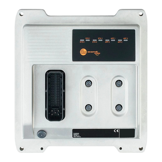
8 Technical data 8.1 CR710S 8.1.1 Mechanical and electric data Control systems CR710S P_MZ_e100_0094 Original Scale Drawing (MTD) Scale: 1:2 ecomatController/37 IEC 61508:2010 SIL 2 LEDs IEC 62061:2005 + A1:2012 + A2:2015 SIL CL 2 if used as safety controller Suited for requirements up to: PL d (ISO 13849-1:2015) AgPL d (ISO 25119:2018,... - Page 27 2 x LED (G) for ETH0 and ETH1 Application LED 4 x three-colour LED (R/G/B) for APP0, APP1, APP2 and APP3, programmable ifm electronic gmbh ● Friedrichstraße 1 ● 45128 Essen We reserve the right to make technical alterations without prior notice! CR710S / page 2...
- Page 28 Output, external, dual channel <1�0 x 10 Lifetime: 8000 h operating time Other characteristic values: see SISTEMA library at ifm�com for download ifm electronic gmbh ● Friedrichstraße 1 ● 45128 Essen We reserve the right to make technical alterations without prior notice!
-
Page 29: 8�1�2 Test Standards And Regulations
ISO 16750-5 AA, BA, BD, CC, DB, DC, DD, only one chemical permitted at a time ifm electronic gmbh ● Friedrichstraße 1 ● 45128 Essen We reserve the right to make technical alterations without prior notice! CR710S / page 4... -
Page 30: 8�1�3 St A / Input Characteristics
≤ 30 kHz Switch-on level > 0�7 VBB Switch-off level < 0�3 VBB Accuracy ± 10 µs ifm electronic gmbh ● Friedrichstraße 1 ● 45128 Essen We reserve the right to make technical alterations without prior notice! CR710S / page 5 19/06/2019... - Page 31 (CSI) pulse width modulation current-controlled resistor input supply output group supply controller ifm electronic gmbh ● Friedrichstraße 1 ● 45128 Essen We reserve the right to make technical alterations without prior notice! CR710S / page 6 19/06/2019...
-
Page 32: 8�1�4 St A / Output Characteristics
GND Digital output (B Range diagnostics min�/max� 0 A / 2�5 A (default) ifm electronic gmbh ● Friedrichstraße 1 ● 45128 Essen We reserve the right to make technical alterations without prior notice! CR710S / page 7 19/06/2019... - Page 33 Accuracy ± 5 % FS (OUT VOLTAGE-A) Step response time 10���90 % < 1�8 ms ifm electronic gmbh ● Friedrichstraße 1 ● 45128 Essen We reserve the right to make technical alterations without prior notice! CR710S / page 8 19/06/2019...
- Page 34 (CSO) pulse-width modulation low side (CSI) pulse-width modulation current-controlled supply output group supply controller ifm electronic gmbh ● Friedrichstraße 1 ● 45128 Essen We reserve the right to make technical alterations without prior notice! CR710S / page 9 19/06/2019...
-
Page 35: 8�1�5 Connectors
ST A AMP, 81 poles, A-coded 1-81: see wiring ST A EPS Sou Product Frame S ifm electronic gmbh ● Friedrichstraße 1 ● 45128 Essen We reserve the right to make technical alterations without prior notice! CR710S / page 10 19/06/2019... -
Page 36: 8�1�6 St A / Wiring
(CSI) pulse-width modulation current-controlled resistor input supply output group supply controller ifm electronic gmbh ● Friedrichstraße 1 ● 45128 Essen We reserve the right to make technical alterations without prior notice! CR710S / page 11 19/06/2019... -
Page 37: 8�2 Cr711S
(≤ 30 kHz) / B 4 x R (0�016���30 kOhm) / B 4 x B (impedance ≤ 3.2 kOhm) ifm electronic gmbh ● Friedrichstraße 1 ● 45128 Essen We reserve the right to make technical alterations without prior notice! CR711S / page 1 19/06/2019... - Page 38 2 x LED (G) for ETH0 and ETH1 Application LED 4 x three-colour LED (R/G/B) for APP0, APP1, APP2 and APP3, programmable ifm electronic gmbh ● Friedrichstraße 1 ● 45128 Essen We reserve the right to make technical alterations without prior notice! CR711S / page 2...
- Page 39 Output, external, dual channel < 1�0 x 10 Lifetime: 8000 h operating time Other characteristic values: see SISTEMA library at ifm�com for download ifm electronic gmbh ● Friedrichstraße 1 ● 45128 Essen We reserve the right to make technical alterations without prior notice!
- Page 40 ISO 16750-5 AA, BA, BD, CC, DB, DC, DD, Only one chemical permitted at a time ifm electronic gmbh ● Friedrichstraße 1 ● 45128 Essen We reserve the right to make technical alterations without prior notice! CR711S / page 4...
-
Page 41: 8�2�3 St A / Input Characteristics
≤ 30 kHz Switch-on level > 0�7 VBB Switch-off level < 0�3 VBB Accuracy ± 10 µs ifm electronic gmbh ● Friedrichstraße 1 ● 45128 Essen We reserve the right to make technical alterations without prior notice! CR711S / page 5 19/06/2019... - Page 42 (default) Observe the notes on the confi guration of the inputs/outputs! (Programming manual "ecomatController CR711S") ifm electronic gmbh ● Friedrichstraße 1 ● 45128 Essen We reserve the right to make technical alterations without prior notice! CR711S / page 6 19/06/2019...
- Page 43 (CSI) pulse width modulation current-controlled resistor input supply output group 0���2 supply controller ifm electronic gmbh ● Friedrichstraße 1 ● 45128 Essen We reserve the right to make technical alterations without prior notice! CR711S / page 7 19/06/2019...
-
Page 44: 8�2�4 St A / Output Characteristics
GND Digital output (B Range diagnostics min�/max� 0 A / 4 A (default) ifm electronic gmbh ● Friedrichstraße 1 ● 45128 Essen We reserve the right to make technical alterations without prior notice! CR711S / page 8 19/06/2019... - Page 45 ± 1�5 % FS (for inductive loads) Range diagnostics min�/max� 0 A / 2�5 A (default) ifm electronic gmbh ● Friedrichstraße 1 ● 45128 Essen We reserve the right to make technical alterations without prior notice! CR711S / page 9...
- Page 46 (CSO) pulse-width modulation low side (CSI) pulse-width modulation current-controlled supply output group 0���2 supply controller ifm electronic gmbh ● Friedrichstraße 1 ● 45128 Essen We reserve the right to make technical alterations without prior notice! CR711S / page 10 19/06/2019...
-
Page 47: 8�2�5 Connectors
ST A AMP, 81-pole, A-coded 1-81: see wiring ST A EPS Sou Product Frame S ifm electronic gmbh ● Friedrichstraße 1 ● 45128 Essen We reserve the right to make technical alterations without prior notice! CR711S / page 11 19/06/2019... -
Page 48: 8�2�6 St A / Wiring
(CSI) pulse-width modulation current-controlled resistor input supply output group 0���2 supply controller ifm electronic gmbh ● Friedrichstraße 1 ● 45128 Essen We reserve the right to make technical alterations without prior notice! CR711S / page 12 19/06/2019... -
Page 49: Maintenance, Repair And Disposal
9 Maintenance, repair and disposal The device is maintenance-free� ► Contact ifm in case of malfunction� ► Do not open the housing as the device does not contain any components which can be maintained by the user� The device must only be repaired by the manufacturer�...
Need help?
Do you have a question about the ecomatController CR710S and is the answer not in the manual?
Questions and answers