Table of Contents
Advertisement
Available languages
Available languages
Quick Links
Advertisement
Table of Contents

Subscribe to Our Youtube Channel
Related Manuals for Peavey Automix 2


Summary of Contents for Peavey Automix 2
- Page 1 A U T O M I X ™ 8 Channel Automatic Mixer OPERATING GUIDE...
- Page 2 Intended to alert the user to the presence of uninsulated Òdangerous voltageÓ within the productÕs enclosure that may be of sufficient magnitude to constitute a risk of electric shock to persons. Intended to alert the user of the presence of important operating and maintenance (servicing) instructions in the literature accompanying the product.
-
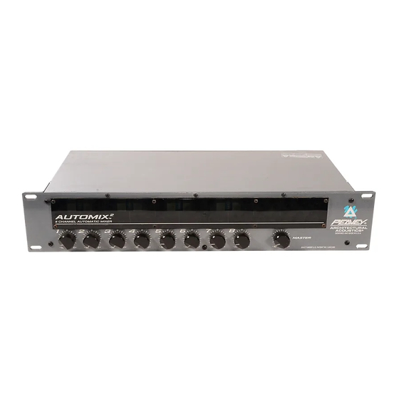
Page 3: Front Panel Features
2 has been designed to easily link multiple units together to form a single mixer with many more inputs (16, 24, 32...). The Automix 2 is supplied with a see-through plexiglass security panel to prevent changes to the installerÕs settings. - Page 4 INTERNAL PANEL INTERNAL PANEL FEATURES DIP SWITCHES Each channel has four DIP switches that control the following functions. MAN/AUTO This switch determines whether the channel is operating in the automatic or manual mode. OFF/MBUS This switch is used to connect the channel to the system mutebus. This allows multiple inputs to be muted simultaneously under external control.
- Page 5 PRIORITY (CHANNEL 1 and 2 ONLY) Turning the priority control clockwise allows one channel to override the others in the mix. It does this by ÒtrickingÓ the gain computing circuits into thinking this channel is louder than the others. Up to 9dB of priority is available. AUX MASTER LEVEL CONTROL This control sets the level of the signal being sent to the Aux Out.
-
Page 6: Back Panel Features
BACK PANEL FEATURES MIC INPUTS For use with low impedance microphones or low level sources. This is a transformer balanced input with an impedance of 2,000½. Input sensitivity for nominal output is -56dBu to -19dBu. LINE INPUTS These allow line level inputs to be used. This is a transformer balanced input through a 30dB resistive pad. -
Page 7: Status Output
MUTE Channels can be muted individually by shorting this terminal to ground. It provides approximately 45dB of attenuation. STATUS OUTPUT The status output is a DC logic output that is high (+5 Volts) when the channel is active and low (0Volts) when the channel is not active. This DC voltage can be used to key video cameras or trigger key lights on active microphones. -
Page 8: Link Switch
Select the mixer to be used as the master and place its link switch in the ÒmasterÓ position. All other mixers in the system should have their link switches in the ÒslaveÓ position. You now have a 16 (or more) channel automatic mixer. The master controls of the unit chosen as ÒmasterÓ... -
Page 9: Specifications
Input Specifications: Function Input z (ohms) Microphone (150 ohms) Line >20k (10K ohms) * Minimum input level (Sensitivity) is the smallest signal that will produce nominal output (2.21dBu) with channel and master controls set for maximum gain. ** Nominal settings are defined s all control set at 0 dB (or 50% rotation for rotary pots. EIN: Phantom Power: Priority (Channels 1 and 2):... -
Page 10: General Specs
Hum and Noise: Output Residual Noise Ref: 0 dBu Main Out -85dBu -84dBu -85dBu Aux Out -80dBu (Hum and noise measurements: 22 Hz to 22 kHz BW) GENERAL SPECS: Remote volume range: Off channel attenuation: Mute: MuteBus: Status output: Power consumption: Weight: Dimensions: AUTOMIX... - Page 11 Wiring Inputs and Outputs: For best results, it is recommended that two-conductor shielded cable is used for all input and output connections. When making connections remember to observe proper polarity. The recommended strip length for the detachable screw terminals is 1/2". Initial Control Settings: Channel Levels Channel Gain Trims...
- Page 12 Setting the Overall Level: Set the master level control (external) for the desired overall output level. This mixerÕs levels are now set and the mixerÕs other features (downward expander, low cut and priorities) can be set as desired for the application. Attaching the Security Panel: Attach the security plexiglass with the eight supplied screws.
- Page 13 (16, 24, 32É). Para evitar modificaciones a las configuraciones del instalador, el mezclador Automix 2 se suministra con un panel de seguridad de plexiglas transparente. Consulte los diagramas del panel delantero en la secci—n de inglŽs de est manual.
- Page 14 permite que varias entradas se silencien simult‡neamente mediante un control externo. Vea BUS DE SILENCIADO en la p‡gina 7. CORTE DE BAJOS/PLANO Este conmutador selecciona el filtro de corte de bajos. El filtro de corte de bajos provee atenuaci—n progresiva de baja frecuencia, que ayuda a minimizar los ruidos no deseados (movimiento de micr—fonos, golpes en la mesa, etc.).
- Page 15 CONFIGURACIîN DEL EXPANSOR DESCENDENTE Pida a otra persona que hable frente a un micr—fono al nivel m‡s bajo que se espera utilizar. Gire lentamente el expansor descendente hacia la derecha, hasta que se atenœe el ruido ambiente de fondo entre las palabras. Tenga cuidado de no excederse. Cuanto m‡s expansor descendente se utilice, menos "natural"...
- Page 16 ENTRADAS DE LêNEA Permiten utilizar entradas con nivel de l’nea. Son entradas equilibradas por transformador a travŽs de un atenuador resistivo de 30 dB. La impedancia de entrada es >20 k½. ENTRADA/SALIDA DE INSERCIîN Es un circuito de se–al que permite insertar un dispositivo externo, tal como un ecualizador, en el camino de la se–al de los canales individuales (consulte el diagrama m‡s abajo).
- Page 17 ESTADO DE SALIDA El estado de la salida es una salida l—gica de CC que est‡ en condici—n alta (+5 V) cuando el canal est‡ activo, y baja (0 V) cuando est‡ inactivo. El voltaje de CC se puede utilizar para excitar videoc‡maras o disparar luces indicadoras en micr—fonos activos.
- Page 18 Prepare un cable de enlace. Conecte los mezcladores segœn el diagrama de m‡s arriba. Seleccione el mezclador a ser utilizado como maestro y coloque su conmutador de enlace en la posici—n ÒmasterÓ (maestro). Todos los otros mezcladores del sistema deben tener sus conmutadores de enlace en la posici—n ÒslaveÓ...
- Page 19 INTRODUCTION Nous vous fŽlicitons pour lÕachat de cet Automix mixeur automatique haute qualitŽ possŽdant huit entrŽes micro/ligne symŽtriques (transformateur). Chaque canal poss•de un contr™le de gain, une alimentation phantom 48 Volt (entrŽes micro), une filtre coupe-bas, une LED dÕactivitŽ/Žcr•tage, un contr™le Aux send et le choix entre une opŽration manuelle ou automatique.
- Page 20 LO CUT/FLAT Ce sŽlecteur actionne le filtre coupe-bas. Ce filtre attŽnue les frŽquences graves afin de minimiser les bruits indŽsirables (manipulation du micro, etc...). La frŽquence de coupure est fixŽe ˆ 100 Hz (-3dB) et la pente du filtre est de 6dB par octave. OFF/+48 Lorsque ce sŽlecteur est en position +48, une alimentation Phantom de +48 Volt est prŽsente aux bornes + et - de lÕentrŽe micro.
- Page 21 panneau avant sur sa position maximum, tous les canaux au niveau nominal et les amplificateurs de puissance en marche et ˆ leur niveau dÕutilisation normale. Lorsque le niveau est Žtabli en dessous du niveau de feedback, aucune manipulation en face avant nÕentra”nera de larsen.
- Page 22 rŽcupŽrer le signal dÕun canal individuel. Ce signal est indŽpendant des manipulation de gain automatiques. Son niveau de sortie nominal est de 2.21dBu (1 Volt). MUTE Les canaux peuvent •tre mis en sourdine individuellement en mettant cette borne ˆ la masse. LÕattŽnuation est de lÕordre de 45dB.
- Page 23 PORT LINK Pour augmenter le nombre dÕentrŽes, plusieurs Automix peuvent •tre reliŽs ensembles. Pour cela, vous avez besoin dÕun simple tourne-vis et dÕune petite longueur de c‰ble 4 conducteurs blindŽ. Suivez unes ˆ unes les Žtapes ci-dessous: Confectionnez un c‰ble adŽquat. Reliez les mixeurs comme indiquŽ...
- Page 24 LautstŠrkeanschlŸsse (Volume). Der Automix leicht miteinander verknŸpfen zu kšnnen, um einen einzelnen Mixer mit vielen (16, 24, 32...) EingŠngen zu erhalten. Der Automix 2 ist mit einem klarsichtigen Plexiglas als Sicherheitspanel ausgestattet, damit festgelegte €nderungen sich nicht ohne weiteres Šndern lassen.
- Page 25 LO CUT/FLAT Hiermit wird der Low Cut Filter gewŠhlt. Der Low Cut Filter bietet eine abrollende Niederfrequenz die ungewollte StšrgerŠusche zu minimalisieren hilft (Mikrofonhandling, versehentliche Tischaneckung, etc..). Der Rolloff beginnt bei 100 Hz (-3dB) und betrŠgt 6dB pro Oktave Filter. OFF/+48 In der Position ã+48Ò...
- Page 26 vorsichtig nicht zu weit zu gehen. Je mehr Downward Expander Sie benutzen, um so ãunnatŸrlicherÒ klingt das System. Anhand dieser Methode erhalten Sie eine gute Ausgangsposition. Die beste Einstellmethode des Downward Expander ist jedoch wŠhrend einem eigentlichen Meeting oder Event. Auf diese Weise lŠ§t sich der Downward Expander fŸr den besten Sound einstellen.
- Page 27 INSERT IN/OUT Hierbei handelt es sich um eine Signalschleife, die es einem externen GerŠt, wie z.B. einem EQ erlaubt in den Signalpfad individueller KanŠle eingeschliffen zu werden (siehe Abb.unten). INSERT BYPASS SCHALTER Wenn kein Signalprozessor benutzt wird, oder es nicht erforderlich ist den Signalprozessor zu umgehen, sollte sich dieser Schalter in der Position ãInÒ...
- Page 28 Ausgang benutzen lŠ§t. Der Nominalausgang betrŠgt 2.21 dBu (1 volt). REMOTE VOLUME Der Hauptpegel des Mixers lŠ§t sich mit einer einfachen Verbindung auf der GerŠterŸckseite fernsteuern. Ein 10k Poti bietet eine annŠhernde DŠmpfung von 0-25dB. Ein 100k Poti bietet eine DŠmpfung von 0-45dB.
- Page 29 Stellen Sie ein Verbindungskabel her. Verbinden Sie die Mixer gemŠ§ obiger Abbildung. Selektieren Sie den Mixer der als Master in Frage kommt und bringen seinen Link-Schalter in die ãMasterÒ Position. Die Link-Schalter aller anderen Mixer im System sollten sich in der ãSlaveÒ Position befinden.
- Page 30 What Peavey Will Do We will repair or replace (at Peavey's discretion) products covered by warranty at no charge for labor or materials. If the product or component must be shipped to Peavey for warranty service, the consumer must pay initial shipping charges. If the repairs are covered by warranty, Peavey will pay the return shipping charges.
-
Page 31: Important Safety Instructions
WARNING: When using electric products, basic cautions should always be followed, including the following: Read these instructions. Keep these instructions. Heed all warnings. Follow all instructions. Do not use this apparatus near water. For example, near or in a bathtub, swimming pool, sink, wet basement, etc. Clean only with a damp cloth. - Page 32 ARCHITECTURAL ACOUSTICS ¨ Features and specifications subject to change without notice. Peavey Electronics Corporation ¥ 711 A Street ¥ Meridian ¥ MS ¥ 39301 (601) 483-5376 ¥ FAX (601) 486-1678 ¥ www.peavey.com ©1998 Printed in the U.S.A. 12/98 80304515...
Need help?
Do you have a question about the Automix 2 and is the answer not in the manual?
Questions and answers