
Related Manuals for Aiphone GH SERIES 0207 AIC


Summary of Contents for Aiphone GH SERIES 0207 AIC
- Page 1 0207 GH SERIES Apartment Intercom System INSTALLATION &OPERATION MANUAL - 1 -...
-
Page 2: General Precautions
11. Do not put anything on or cover the unit with cloth, etc. Fire or unit trouble could result. 12. For DC powered systems, use Aiphone power supply model specified with system. If non-specified product is used, fire or malfunction could result. -
Page 3: System Configuration
SYSTEM CONFIGURATION GH-VA + GH-DA/A + GH-NS, GH-10K GH-VA PS24 Max. 5 (3 per trunk) GH-DA/A GH-VA + GH-DA/A + GH-SW GH-DA/A + GH-NS, GH-10K PS24 GH-DA/A + GH-SW GH-MK [14] PS24 Max. 2 Max. 48 Max. 25 / Trunk Trunk #6 ~ #2 GH-1KD... -
Page 4: Standard System Configuration
Standard System Configuration (1) Audio signal line (2) Video signal line (3) Power supply line a. Entrance station (For details, see 2-1 and 2-2) [1] Audio/video + digital name scrolling type GH-VA + GH-DA/A + GH-NS, GH-10K [2] Audio/video + direct selection type GH-VA + GH-DA/A + GH-SW [3] Audio + digital name scrolling type GH-DA/A + GH-NS, GH-10K... -
Page 5: Table Of Contents
SYSTEM CONFIGURATION Standard System Configuration Expanded System Configuration Wiring Distance COMPONENTS Unit (Entrance Station) Combination Examples for Entrance Station, Unit (Bus Control Unit and Others) Residential Station, Security Guard Station MOUNTING Mounting the Entrance Station (1) Mounting the Entrance Station (2), (3) Bus Control Unit and Power Supply Residential Station, Optional Handset Security Guard Station (Desk-top Mounting Using the GFW-S Stand), (Mounted on Wall) - Page 6 GH-VA + GH-DA/A + GH-NS, GH-10K PS24 GH-VA GH-DA/A Max. 8 (3 per trunk) GH-MK PS24 Max. 2 GH-VA + GH-DA/A + GH-NS, GH-10K PS24 GH-VA GH-DA/A Max. 8 (3 per trunk) GH-MK PS24 Max. 2 PS24 GH-VBX GH-BC PS24 GH-BCX/A PS24 GH-BC...
-
Page 7: Expanded System Configuration
Expanded System Configuration Diagram 1. Common trunk line #1, 2 2. Sub trunk line #1 - 4 Sub trunk line #2 - #4 are the same as #1. Maximum 125 units per sub trunk line. (1) Audio signal line (2) Video signal line (3) Power supply line a. -
Page 8: Components
COMPONENTS [10] [11] [12] [15] [16] [18] [20] [19] [21] [22] [23] [25] [26] [27] Unit (Entrance Station) [1] Speech module panel GH-DP [2] Speech module GH-DA/A [3] Camera module panel GF-VP [4] Camera module GH-VA [5] 1-call button panel GF-1P [6] 2-call button panel GF-2P [7] 3-call button panel GF-3P [8] 4-call button panel GF-4P... - Page 9 AIPHONE AIPHONE Combination Examples for Entrance Station 1. Audio only. Direct selection (8 stations). 2. Audio/video. Direct selection (8 stations). 3. Audio only. Digital name scrolling. 4. Audio/video. Digital name scrolling. AIPHONE AIPHONE [10] Unit (Bus Control Unit and Others)
-
Page 10: Security Guard Station
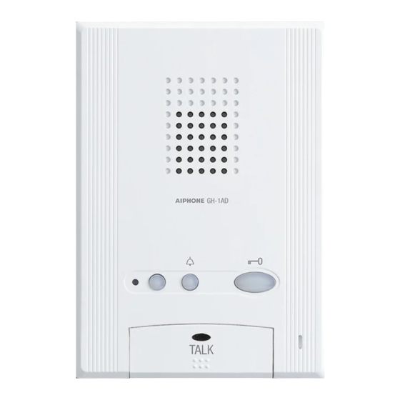
Residential Station [1] Audio residential station GH-1AD [2] Color monitor residential station GH-1KD [3] Mounting screws (enclosed with GH-1AD and GH-1KD) [4] Black-and-white monitor residential station GH-1MD [5] Mounting screws (enclosed with GH-1MD) [6] Optional handset GH-HS (mounting screws are attached back side) GH-HS can be installed only for the color monitor residential station GH-1KD. -
Page 11: Mounting
Do not mount the back box on a surface that is recessed by 15 mm (1/2") or more from the external surface of the wall. Up to 6 GH-SW modules can be used. If you would like to connect 7 modules or more, please contact Aiphone. Peel off protection film on GH-NS display. -
Page 12: Mounting The Entrance Station (2)
GH-DA/A GH-DA/A GH-SW GH-DA/A Mounting the Entrance Station (2) 1. Remove the terminal cover. 2. From the speech module to the next module, insert the attached connector into the socket. Make sure to run the cable under the terminal cover for protection. 3. -
Page 13: Bus Control Unit And Power Supply
GH-BC GH-VBC GH-4Z GH-BCX/A GH-VBX – – PS-2410LC PS-2410DIN Bus Control Unit and Power Supply [1] Din rail (W-DIN11) [2] Screw hole [3] POWER switch [4] Power On LED (green) [5] Lock release lever [6] Wall mounting screws (x2) 1. Mount GH-BC and GH-VBC to the Din rail. Click unit into place. -
Page 14: Optional Handset
GH-1AD GH-1KD SW1 A Do not remove the wires (For end users) 0.65 10 9 R1 R2 R1 R2 C K KE GH-1MD Residential Station [1] Mounting screws (x2) [2] Mounting bracket [3] 1-gang box or round back box [4] Terminal block (GH-1AD, GH-1KD) 1. - Page 15 Security Guard Station (Desk-top Mounting Using GFW-S Stand) [1] Screws included with GFW-S (x4) [2] Cable tie included with GFW-S 1. Separate the mounting bracket and the protective cover from the back of the unit. 2. Mount the mounting bracket to GFW-S as shown in the drawing. 3.
-
Page 16: Wiring Standard System
WIRING Standard system Capacity 5 Entrance stations 2 Security guard stations 48 Residential stations Homerun wiring with GH-4Z Trunk line #1 1Px2 1Px2 1Px2 1Px2 Doorbell Doorbell GH-1KD GH-1MD GH-1MD, unlike GH-1KD, is only available to connect on a trunk line with GH-4Z used Distribution point... - Page 17 Homerun wiring with GH-4Z Trunk line #1 R1 R2 GH-1KD R1 R2 1Px2 OUT 3 Doorbell 1Px2 OUT 1 R1 R2 GH-1MD Doorbell 1Px2 GH-BC Distribution point PS24 Light control Orange Timer Blue 1Px2 Orange GH-RY White Light GH-DA/A R1 R2 ELB ELC ELM RY RY A1 A2 GH-VA...
- Page 18 GH-VA #2 - #5 GH-NS #2 , #3 GH-NS #1 + – A1A2 GH-10K #1 CN100 1 2 3 4 GH-DA/A #2 , #3 GH-DA/A #4 , #5 GH-MK GH-MK #1 1 2 3 4 1 2 3 4 PS-2410LC PS-2410LD PS24 GH-VA #1 + –...
-
Page 19: Standard System (2) Station-To-Station Wiring
IN OUT R1R2 R1R2 C CE K KE R1, R2 IN OUT IN OUT B1B2 B1B2 R1R2 R1R2 C CE K KE IN OUT IN OUT B1B2 B1B2 R1R2R1R2 C CE K KE GH-1KD IN OUT IN OUT B1B2 B1B2 R1R2R1R2 C CE K KE GH-VBC... - Page 20 GH-4Z GH-4Z GH-4Z GH-VBC GH-BC GH-4Z GH-4Z GH-1KD - 20 - B1 B2 R1 R2 C CE K KE B1, B2 Do not remove the wires! R1, R2 IN OUT R1R2 R1R2 C CE K KE R1, R2 IN OUT IN OUT B1B2 B1B2 R1R2R1R2...
-
Page 21: Standard System (3) Homerun Wiring
Standard System (3) Homerun Wiring [1] 4-way video junction unit GH-4Z • For the terminating GH-4Z (maximum of 6 units per trunk), set the setting switch (SW1) to "A". [2] Residential station GH-1KD, GH-1AD, GH-1MD • For GH-1KD, set the setting switch (SW1) to "A". [3] Short lead •... -
Page 22: Expanded System
Expanded system Capacity Trunk line #1 16 Entrance stations 4 Security guard stations 500 Residential stations GH-1KD GH-1KD Distribution point COMMON1 Entrance #2 - #8 GH-NS #2 , #3 GH-NS 1Px2 #4 - #6 GH-NS 1Px3 #7 , #8 PS24 Door release 1Px2 Entrance station... - Page 23 SUB1A Distribution point 1Px2 GH-BC PS24 1Px2 GH-BCX/A COMMON1 PS24 1Px2 Entrance #2 - #8 1Px2 GH-NS #2 , #3 1 2 3 4 1 2 3 4 1 2 3 4 1 2 3 4 1 2 3 4 1 2 3 4 1Px2 1 2 3 4...
- Page 24 COMMON1 COMMON2 GH-VA #1 GH-DA/A #1 1 2 3 4 1 2 3 4 1 2 3 4 1 2 3 4 GH-NS #1 PS24 1 2 3 4 1 2 3 4 1 2 3 4 1 2 3 4 GH-VA #2 - #8 GH-DA/A...
-
Page 25: External Signaling Relay Connection
[6] Buzzer [7] Entrance light • GH-RY contact specifications: AC/DC 24 V, 0.5 A ([3], [4]) When connecting GH-RY to GH-1AD, GH-1KD, GH-1MD or GH-MK, the separate option connector is required. Please consult your AIPHONE Distributor. - 25 - GH-RY... -
Page 26: Names (Entrance Station)
NAMES (ENTRANCE STATION) GH-VA GH-DA/A GH-DA/A GH-SW [11] Entrance Station 1. Digital name scrolling entrance station • Camera module GH-VA [1] Camera • Speech module GH-DA/A [2] Speaker [3] In Use LED [4] Microphone • Digital name scrolling module GH-NS [5] Display [6] Cancel button (or set and return) [7] Back search button (or move cursor to the left) -
Page 27: Residential Station (Gh-1Md)
GH-1MD Residential station (GH-1MD) [1] Video monitor 4 inch black and white CRT [2] Microphone [3] Speaker [4] Light button / Security guard station call button [5] Door release / Monitor button [6] Talk button [7] Talk LED [8] Monitor brightness control [9] Receive volume control [10] Call tone volume control [10]... -
Page 28: Setting Up (Entrance Station)
SETTING UP (ENTRANCE STATION) 95cm 65cm 65cm GH-VA GH-VA 24cm 113cm 24cm Adjusting the Camera Angle 1. View from the initial camera position 2. Changing the camera angle • Remove the rubber cap. Move the lever to the desired position. ∗... -
Page 29: Making Adjustments With The Mounting Gauge
Making Adjustments with the Mounting Gauge [1] Mounting gauge • To mount multiple rows of panels, apply the mounting gauge to the mounting bracket. While using the mounting gauge to make adjustments, tighten the screws. ∗ There is a mounting gauge for the built-in back box of GF-2B and GF-3B. -
Page 30: Setting Up The System
GH-BC GH-NS GH-SW GH-SW GH-NS GH-DA/A Setting up the System 1. Make sure that all units are installed and wired properly. Turn on the power switch in GH-BC. When the system includes GH- NS, program the resident information (names and room numbers) in advance. -
Page 31: Programming (Gh-Ns)
GH-NS Enter Program Mode DISPLAY YOUR OPERATION WELCOME RE-ENTER ID CODE ID CODE = + 4 digit Select Menu & Quit DISPLAY SELECT LANGUAGE MENU SELECT LANGUAGE CHANGE ID CODE ACCESS CODE RESIDENT INFO SET TIMER DECIDE & NEXT CHANGE GREETING TRANSFER DATA SCROLL SPEED QUIT... - Page 32 DISPLAY YOUR OPERATION SELECT LANGUAGE DECIDE & NEXT MENU ENGLISH FRANCAIS BACKWARD DEUTSCH ESPANOL NEDERLANDS SELECT LANGUAGE ENGLISH DECIDE & BACK DISPLAY YOUR OPERATION CHANGE ID CODE DECIDE & NEXT Enter new ID code CHANGE ID CODE 1111 INITIAL ID NEW ID (4-digit) CHANGE ID CODE 0123...
-
Page 33: Program Mode (Gh-Ns)
Program Mode (GH-NS) 1. Menu 1: Select language Choose language to be displayed on GH-NS. 2. Menu 2: Change ID code Enter new ID code starting with "∗", then 4-digit number. (Example: ∗1234) 3. Menu 3: Set access code Enter new 4-digit Access Code. (Example: 1234) •... -
Page 34: Setting Up (Security Guard Station)
SETTING UP (SECURITY GUARD STATION) GH-MK Enter Program Mode DISPLAY YOUR OPERATION AIPHONE RE-ENTER ID CODE INITIAL ID CODE ID CODE = + 4 digit Select Menu & Quit DISPLAY SELECT LANGUAGE MENU SELECT LANGUAGE CHANGE ID CODE RESIDENT INFO... -
Page 35: Programming (Gh-Mk)
Save programmed data and resident information data to your PC is recommended. b. Programming with GH-MK • Confirm that "AIPHONE" is shown on the Display, indicating that the system is in standby mode. • First, set the system to program mode. (For details, see 9-2.) ∗... - Page 36 DISPLAY YOUR OPERATION SELECT LANGUAGE DECIDE & NEXT MENU ENGLISH FRANCAIS BACKWARD DEUTSCH ESPANOL NEDERLANDS SELECT LANGUAGE ENGLISH DECIDE & BACK DISPLAY YOUR OPERATION CHANGE ID CODE DECIDE & NEXT Enter new ID code CHANGE ID CODE 1111 INITIAL ID NEW ID (4-digit) CHANGE ID CODE 0123...
-
Page 37: Program Mode (Gh-Mk)
Program Mode (GH-MK) 1. Menu 1: Select language Choose language to be displayed on GH-MK. 2. Menu 2: Change ID code Enter new ID code starting with "∗", then 4-digit number. (Example: ∗1234) 3. Menu 3: Write in resident information Register room #s and resident names. -
Page 38: Operations (Entrance Station)
OPERATIONS (ENTRANCE STATION) 10-1 DISPLAY YOUR OPERATION Press button intermittently WELCOME or hold down for 2 sec. to show in succession. BACKWARD SMITH CALLING SMITH DISPLAY YOUR OPERATION Press ROOM #. WELCOME SMITH CALL CALLING SMITH DISPLAY YOUR OPERATION WELCOME ENTER 'SMITH' (example) ENTER A LETTER... -
Page 39: Door Release
10-2 Calling the Security Guard Station Press the call button once. You will hear a low-volume call tone from the entrance station. 10-3 DISPLAY YOUR OPERATION WELCOME Enter Access Code 4567 DOOR OPEN When there is no code, Door Release 1. - Page 40 11-2 Calling from the Doorbell (at Individual Door) 1. The doorbell button is pushed. A call tone sounds as long as the button is held down. 2. A different call tone sounds (there is no communication available). 11-3 Door Release 1.
-
Page 41: Emergency Alarm
11-7 Emergency Alarm 1. Press and lock the emergency alarm switch (or when there is a line - off trouble). 2. An alarm will sound from the residential station. 3. When there is a call from the security guard station, the alarm will change to a standard call tone and sound for approximately 45 seconds. -
Page 42: Operations (Security Guard Station)
OPERATIONS (SECURITY GUARD STATION) 12-1 Replying to a Call from an Entrance Station 1. When a call is received from an entrance station, a call tone will sound for approximately 10 seconds at the security guard station and the entrance station number will be displayed. Lift the handset and respond. -
Page 43: Calling An Entrance Station
Making a call by entering letters and selecting the corresponding name NOTES: 1. Pressing the search button for approximately 2 - 43 - DISPLAY YOUR OPERATION Press button intermittently AIPHONE or hold down for 2 sec. to show in succession. BACKWARD FORWARD SMITH Scroll... -
Page 44: Calling Another Security Guard Station
12-5 DISPLAY YOUR OPERATION Press button intermittently or hold AIPHONE down for 2 sec. to show in succession. BACKWARD SECURITY GUARD A Scroll CALLING SECURITY GUARD A DISPLAY YOUR OPERATION Press ROOM #. AIPHONE SECURITY GUARD A CALL When there is no Room #,... -
Page 45: Calling From The Doorbell Button
12-7 E01 101 SMITH Reception mode Setting While in standby mode, press "∗", "1" and "∗" on a security guard station to display "RECEPTION MODE". In this mode, you can intercept a call from an entrance to a tenant, and transfer the calls directly to the security guard station. -
Page 46: Technical Precautions
TECHNICAL PRECAUTIONS Technical precautions • Operating temperature: Entrance Station: Residential Station: Security Guard Station:0 °C to 40 °C Control Unit: • Mounting location: Do not install the entrance station in a place where there would be a bright light behind a visitor (or where there would be a bright background) or in a place where the camera lens would be directly exposed to sunlight or a bright... -
Page 47: Warranty
This warranty does not cover batteries or damage caused by batteries used in connection with the unit. This warranty covers bench repairs only,and any repairs must be made at the shop or place designated in writing by Aiphone. Aiphone will not be responsible for any costs incurred involving on site service calls.
Need help?
Do you have a question about the GH SERIES 0207 AIC and is the answer not in the manual?
Questions and answers