
Related Manuals for Advantech SKY-524


Summary of Contents for Advantech SKY-524
- Page 1 User Manual SKY-524 2U 4 Node Hybrid Server with High Density and Flexible Storage capability, support dual 10GbE and 2x PCIe x16 slots per node.
- Page 2 No part of this manual may be reproduced, copied, translated or transmitted in any form or by any means without the prior written permission of Advantech Co., Ltd. Information provided in this manual is intended to be accurate and reliable. How- ever, Advantech Co., Ltd.
- Page 3 Whether your new Advantech equipment is destined for the labo- ratory or the factory floor, you can be assured that your product will provide the reliability and ease of operation for which the name Advantech has come to be known.
- Page 4 There are no user serviceable components inside. (2) Do not operate controls, make adjustments, or perform procedures to the laser device other than those specified herein. (3) Allow only authorized service technicians to repair the laser device. SKY-524 User Manual...
- Page 5 Repair of the device may only be carried out by trained service personnel. Advantech recommends that a service contract be obtained with Advantech Service and that all repairs also be carried out by them. Otherwise the correct functioning of the device may be compromised.
- Page 6 CAUTION: Any changes or modifications not expressly approved by the party responsible for compliance could void the user's authority to operate this equip- ment. Contact information: Advantech Co., Ltd. Website: www.advantech.com.tw Address: No.1, Alley 20, Lane 26, Rueiguang Road Neihu District, Taipei, Taiwan 114, R.O.C. TEL: +886-2792-7818 SKY-524 User Manual...
- Page 7 You must become familiar with the safety information in this guide before you install, operate, or service Advantech products. Machine Room Environment ...
- Page 8 Advantech, your authorized Advantech partner, or their agents. Equipment Modifications Do not make mechanical modifications to the system. Advantech is not respon- sible for the regulatory compliance of Advantech equipment that has been mod- ified. Equipment Repairs and Servicing ...
- Page 9 0129 H.S R3 I-Skylake-SP S-165W 1960081155N101 CoolJag For CPU1 108x78.0x25.5-SC Heatsink Heatsink I-Skylake-EP S- 1960081155N001 CoolJag For CPU0 165W 107.75x78.0x25.5-SC SKY-524 PCIex16 riser Card, 9691Y524500 Advantech left site Riser Card SKY-524 PCIex16 riser Card, 9691Y524600 Advantech right site 2200W 96PSRM-A2K2W1UT...
- Page 10 It should be free of marks and scratches and in perfect working order upon receipt. When unpacking the SKY-524, check it for signs of ship- ping damage. (For example, damaged box, scratches, dents, etc.) If it is damaged or it fails to meet the specifications, notify our service department or local sales repre- sentative immediately.
-
Page 11: Table Of Contents
Server Management ..............70 3.2.6 Security ..................74 3.2.7 Boot..................... 74 3.2.8 Save & Exit ................. 75 Chapter Chipset Software Installation Utility and BMC Update77 Before You Begin ..................78 Introduction ..................... 78 Windows OS Driver Setup ..............79 SKY-524 User Manual... - Page 12 . 87 Watchdog Timer Overview..............88 Programming the Watchdog Timer ............88 Appendix B Exploded Diagram and Parts List..91 Exploded Diagram and Parts List ............92 Table B.1: Parts List ..............92 Appendix C RoHS Declaration......93 SKY-524 User Manual...
-
Page 13: Chapter 1 Overview
Chapter Overview... -
Page 14: Introduction
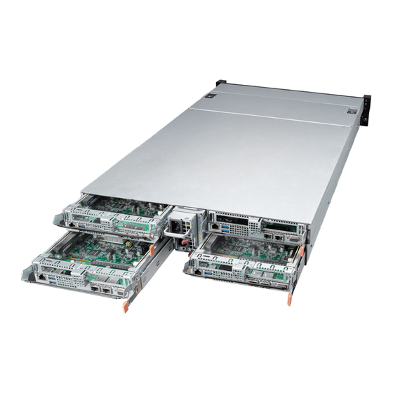
Introduction The Advantech SKY-524 server is a 2U 4 Node Hybrid Server with 24 x 2.5” drives. It is a highly configurable high performance server designed to balance server-class processing with flexible I/O and offload density in limited 2U cabinet space. The sys- tem is a cost effective, robust platform optimized for high reliability in network, edge and industrial computing. -
Page 15: System Specifications
Air Shroud Power status, HDD Status, Fan Status, Location, LED Indicators Overheat, Node Status, Node Alert Miscellaneous Remote Advantech Remote Monitoring Utility Management Operating Non-operating Temperature 0 ~ 35 °C (32 ~ 95 °F) -40 ~ 60 °C (-40 ~ 140 °F) 95% @ 40 °C, non-con-... -
Page 16: System Dimension
System Dimension 1. SKY-524 System Dimension 438.00 Unit: mm 446.00 763.60 763.60 573.10 573.10 243.10 243.10 449.00 52.60 52.60 484.60 465.00 SKY-524 User Manual... -
Page 17: System Layout, Led, Jumpers And Connectors
2. Sky-524 Node Dimension Unit: mm 186.30 System Layout, LED, Jumpers and Connectors This chapter mainly focuses on the system layout, LED definition, jumper settings and the connectors of SKY-524. 1.5.1 System Layout 8 x NVMe /SAS/SSD Drives 6* Drives for... - Page 18 But please note that the system fan will shut down 10 seconds after the whole system shuts down as a protection mechanism. (1+1) 2200W Redundant PSU Node 1 Node 3 Node 4 Node 2 SKY-524 User Manual...
- Page 19 Supports half height / half length PCIe card Supports half height / half length PCIe card Flexible I/O port con gura on bl / Enclosure management (via IPMI) 10GbE RJ45 (default) 10GbE SFP+ 1GbE SKY-524 User Manual...
-
Page 20: Led Definitions
CPU0 LGA3647 socket LGA3647 socket Intel X557 chip Intel C622 PCH with cut n heatsink with full n heatsink 2 x HH/HL On board RAID M.2 2280 B key 24*DDR4 DIMM slot expansion card 1.5.2 LED Definitions SKY-524 User Manual... - Page 21 Node LED (Rear) Status Color Description Blue Node receives chassis identity On command. Node Locate LED Nodes working normal Node alert happened: voltage abnormal, temper- ature abnormal and watchdog event happened. Node Alert LED Node working normal SKY-524 User Manual...
-
Page 22: Jumpers
Blinking Green 10G bps Active LAN 2 / LAN3 LED No Link 1.5.3 Jumpers Label Function Default JCMOS1 CMOS clear JME1 ME update Keep CMOS data / Disable ME update Clear CMOS data / Enable ME update SKY-524 User Manual... -
Page 23: Connectors
High density slot with PCIe Gen3 x16 signal from CPU0 for Left CPU_L_PCIEX16_1 Side PCIe Riser Card LPC2 LPC port for debug & TPM module LAN1 IPMI dedicated LAN USB1_2 Rear panel 2*USB2.0 ports LAN2 10GbE LAN LAN3 10GbE LAN VGA1 Rear panel VGA port SKY-524 User Manual... -
Page 24: Block Diagram
Block Diagram SKY-524 User Manual... -
Page 25: System Memory
System Memory SKY-524 has twenty-four 288-pin memory slots per node for DDR4 2133/2400/2666 MHz memory modules with maximum capacity of 768 GB (Maximum 32 GB for each DIMM). SKY-524 supports registered DIMMs ONLY. Memory Installation Procedures DIMM Configurations Quantity of memory module installed... - Page 26 SKY-524 User Manual...
-
Page 27: Chapter 2 Setting Up
Chapter Setting up... -
Page 28: Before You Begin
Components and electronic circuit boards can be damaged by discharges of static electricity. Working on a system that is connected to a power supply can be extremely dangerous. Follow the guidelines below to avoid damage to SKY-524 or injury to yourself. -
Page 29: Installing Node Components
CPUs, memory modules and add-on cards. 2.2.1 Removing the Node Follow these instructions to remove SKY-524 node from whole system to do the CPU and key parts assembly. Push the latch (lock mechanism) to the direction right as the diagram below shows. -
Page 30: Installing The Cpu And Heatsink Per Node
Installing the CPU and Heatsink per Node Follow the steps below to install CPUs and CPU heatsinks. Locate the CPU sockets - The CPU0 must be installed first. Please see below diagram shows the location of CPU0 and CPU1. SKY-524 User Manual... - Page 31 Remove CPU dust cover from the CPU socket. SKY-524 supports dual CPUs per node, before putting the CPU on board, please assemble the CPU with heatsink socket. SKY-524 User Manual...
- Page 32 Assemble the heatsink and the sub assembly as in the previous step. Carefully align the triangle mark on the CPU against the triangle mark on the CPU socket then place the CPU with heatsink into the CPU socket. SKY-524 User Manual...
- Page 33 For thermal considerations, please follow the diagram and use full fin heatsink on CPU0, cut fin heatsink on CPU1. Use a T30 Torx screwdriver tighten the screws in the order of 1,2 -> 3,4 with a torque of 12lbf. SKY-524 User Manual...
- Page 34 4,3 -> 2,1, then lift the CPU and heatsink up. After the CPU and heatsink assembly has finished, please use two screws to assemble the air ducts on board as shown below. SKY-524 User Manual...
-
Page 35: Installing The Memory Per Node
Align the memory module with the slot. When inserted properly, the memory slot locking levers lock automatically onto the indentations at the ends of the mod- ule. Follow the recommended memory population table to install the other mem- ory modules. SKY-524 User Manual... -
Page 36: Installing The Riser Cards (Right Side And Left Side) Per Node
Then pull up the PCIe cards with the brackets. Unscrew one screw on the low profile bracket and remove the bracket. Follow- ing the horizontal direction, plug the PCIe card into the PCIex16 slot on the left side of PCIe rider card. Riser Card Bracket SKY-524 User Manual... -
Page 37: M.2 2280 Installation Per Node
Under the PCIe Card (R), there is an M.2 2280 B Key slot. In order to install the M.2 2280 SATA interface SSD, remove the screw circled in red below. Insert the M.2 2280 B key (in red square) below then affix the screw back in. SKY-524 User Manual... -
Page 38: Installing Hard Drives
2.2.6 Installing Hard Drives SKY-524 supports 24 x 2.5” hard drives. Eight of them support 2.5" NVMe drives shown in red on HDD tray button; the other 16 HDD trays are orange. Please follow instructions below to install a hard drive. - Page 39 Press the locking lever latch and pull the locking lever open, then slide the HDD tray out. Place a hard drive into the drive tray and use the screws to secure the HDD, then insert the HDD tray back into the chassis and press the locking lever to secure the tray. SKY-524 User Manual...
-
Page 40: Removable Fan
2.2.7 Removable FAN Undo the screw on the top cover and press on both right side and left side to open the top cover. SKY-524 User Manual... - Page 41 Follow illustration and press directly on the clip to pull up the fan from fan mod- ule. Note! When there are two system fans showing alert, the system will shut down as a protect mechanism. SKY-524 User Manual...
-
Page 42: Rack Mounting
Rack Mounting After installing the necessary components, SKY-524 can be mounted in a rack using the optional rack mounting kit. We strongly recommend that the minimum depth of the cabinet is 1100mm. 2.3.1 Slide Rail installation Please read prior to installation. The server slides are developed for 1U or 2U aplica- tions of which the system load does not exceed 75lbs. - Page 43 Align the positioning pin to the desired complete U location, and pull the bracket forwards to lock it to the post. The bracket is locked to the post after you hear a “click” sound. Release the locking latch upward. SKY-524 User Manual...
- Page 44 After the inner member goes in, push up/ down the disconnect lever to unlock the slides and keep pushing the chassis to the fully closed position. Screw the system into the cabinet. SKY-524 User Manual...
- Page 45 M5 Screw Tips. For EIA square hole diecasting Press the latch to transfer from square to cylinder (for EIA 7.5 round hole) SKY-524 User Manual...
- Page 46 Uninstall the bracket Remove the inner member SKY-524 User Manual...
- Page 47 Fiabilité de la mise - Fiable mise à la terre de l'équipement monté en rack doit être maintenue. Une attention particulière devrait être accordée à fournir connexions autres que les connexions directes sur le circuit de branche (par exemple l'utilisation de multiprises). SKY-524 User Manual...
- Page 48 SKY-524 User Manual...
-
Page 49: Chapter 3 Ami Bios
Chapter AMI BIOS... -
Page 50: Introduction
The Setup program uses a number of menus for making changes and turning special features on or off. This chapter describes the basic navigation of the SKY-524 setup screens. AMI's BIOS ROM has a built-in Setup program that allows users to modify the basic system configuration. -
Page 51: Bios Setup
System Date using the <Arrow> keys. Enter new values through the keyboard. Press the <Tab> key or the <Arrow> keys to move between fields. The date must be entered in MM/DD/YY format. The time must be entered in HH:MM:SS format. SKY-524 User Manual... -
Page 52: Advanced Bios Features Setup
3.2.2 Advanced BIOS Features Setup Select the Advanced tab from the SKY-524 setup screen to enter the Advanced BIOS setup screen. You can select any of the items in the left frame of the screen, such as ACPI Settings, to go to the sub menu for that item. You can display an Advanced BIOS Setup option by highlighting it using the <Arrow>... - Page 53 3.2.2.1 Trusted Computing Security Device Support Enables or disables BIOS support for security devices. Note! Purchase Advantech LPC TPM module to enable TPM function. P/N: PCATPM-00A1E. SKY-524 User Manual...
- Page 54 3.2.2.2 ACPI Settings Enable Hibernation Enable or Disable Hibernation. Lock Legacy Resources Enable or Disable Lock Legacy Resources. Power on by Modem Enable or Disable Power On by Modem SKY-524 User Manual...
- Page 55 3.2.2.3 ITE8528 Super IO Configuration Serial Port 1 Configuration – Serial Port Enable or Disable Serial Port 1. SKY-524 User Manual...
- Page 56 ACPI OS to pro- tect the system from overheat damage. CPU Warning Temperature Set the CPU warning temperature threshold. When the system reaches the warning temperature, the speaker will beep. SKY-524 User Manual...
- Page 57 Fan Configuration There is only one fan zone in SKY-524. – Zone 0 for 4 Nodes System Fan Zone 0 Mode There are two options for customer choose: Full speed and Smart Fan Mode. SKY-524 User Manual...
- Page 58 3.2.2.5 Serial Port Console Redirection Console Redirection Enable or Disable console redirection feature. Console Redirection Settings SKY-524 User Manual...
- Page 59 'stop' signal can be sent to stop the data flow. Once the buffers are empty, a 'start' signal can be sent to re-start the flow. Hard- ware flow control uses two wires to send start/stop signals. Options available: None/Hardware RTS/CTS. SKY-524 User Manual...
- Page 60 Redirection After BIOS Post 3.2.2.6 PCI Subsystem Settings Above 4G Decoding Enable or disable 64-bit capable devices to be decoded in above 4G address space. This setting is available only if system supports 64-bit decoding. SKY-524 User Manual...
- Page 61 3.2.2.7 Network Stack Network stack Enable or disable UEFI Network Stack for Network access under BIOS setup. 3.2.2.8 CSM Configuration CSM Support Enable or disable CSM support SKY-524 User Manual...
- Page 62 Selects the USB transfer time-out value. [1,5,10,20sec] Device Reset Time-out Selects the USB device reset time-out value. [10,20,30,40 sec] Device Power-up Delay This item appears only when device power-up delay item is set to [manual] SKY-524 User Manual...
-
Page 63: Platform Configuration
3.2.3 Platform Configuration 3.2.3.1 PCH Configuration SKY-524 User Manual... - Page 64 Select active video type as on board device or PCIE device. Default auto is PCIE device priority higher than on board device. – RTC wake system from S4/S5 Enable or Disable system wake on alarm event. When enabled, system will wake on the day and time specified. SKY-524 User Manual...
- Page 65 PCIeM.2 B+M Key Configuration – PCIe M.2 Slot Enable or disable PCI Express M.2 Root Port – PCIe Speed Change the link speed with "Auto / Gen1 / Gen2 / Gen3" items. PCH sSATA/M.2 Configuration SKY-524 User Manual...
- Page 66 Enable or disable on board LAN1/LAN2 from Intel X557AT2 Controller sup- port. – LAN1 PXE OpROM Enable or disable Legacy Boot option for LAN1 from Intel X557AT2 control- ler. – LAN2 PXE OpROM Enable or disable Legacy Boot option for LAN2 from Intel X557AT2 control- ler. SKY-524 User Manual...
-
Page 67: Socket Configuration
3.2.3.2 Server ME Configuration This page shows the operating ME firmware version and state. 3.2.4 Socket Configuration SKY-524 User Manual... - Page 68 Set to enable or disable. DCU Streamer Prefetch Enable prefetch of next L1 data line based upon multiple loads in same cache line. DCU IP Prefetcher Enable prefetch of next L1 line based upon sequential load history. SKY-524 User Manual...
- Page 69 MSR 31h Bit[0] - A write of 1 selects the DCU mode as 16KB 4-way with ECC. AES-NI Enable or disable AES-NI support. Core Disable Bitmap (Hex) Hex value for CPU Core disable, default value 0 is enable all cores. SKY-524 User Manual...
- Page 70 3.2.4.2 UPI Configuration – UPI status – Link Speed Mode Select the QPI link speed as either the POR speed (Fast) or default speed (Slow). SKY-524 User Manual...
- Page 71 Allows for selecting the QPI Link frequency. – Link L0p Enable Enable or disable QPI Link0p. – Link L1 Enable Enable or disable QPI L1. 3.2.4.3 Memory Configuration NUMA Enable or disable Non-uniform Memory Access (NUMA). Memory Topology SKY-524 User Manual...
- Page 72 3.2.4.4 IIO Configuration PCI-E ASPM Support (Global) Enable or disable the Active State Power Management for all PCI-Express slots. SKY-524 User Manual...
- Page 73 Socket 0 Configuration SKY-524 User Manual...
- Page 74 IOU0-Port 1C (PCIex8 PM8222) IOU1-Port 2A (PCIex8 PCH) IOU2-Port 3A (PCIex16 PCIe Left Riser Card) – Link Speed Select target link speed as Auto, Gen1, Gen2, Gen3. SKY-524 User Manual...
- Page 75 Socket 1 Configuration SKY-524 User Manual...
- Page 76 IOU0-Port 1A (PCIex16 PCIe Right Riser Card) IOU2-Port 3A (PCIex4 NVMe1) IOU3-Port 3B (PCIex4 NVMe2) – Link Speed Select target link speed as Auto, Gen1, Gen2, Gen3. – Hot plug Capable SKY-524 User Manual...
- Page 77 Intel VT for Direct I/O (VT-d) – Intel VT for Direct I/O (VT-d) Enable or disable Intel Virtualization Technology for directed I/O (VT-d) by reporting the I/O device assignment to VMM through DMAR ACPI tables. SKY-524 User Manual...
- Page 78 – Intel VMD for Volume Management Device Intel® VMD enables hot swap replacement of NVMe* SSDs from the PCIe* bus without shutting down the system while standardized LED management helps provide quick identification of SSD status. SKY-524 User Manual...
- Page 79 SpeedStep (P-state) When enabled, OS sets CPU frequency according to load. When disabled, CPU frequency is set at max non-turbo. Boot performance mode Select the performance state that BIOS will set before the OS hands off. SKY-524 User Manual...
- Page 80 Enable or disable autonomous C-State control for CPU cores. Default is disable. CPU C6 report Enable or disable CPU C6 report. Default is disable. Enhanced Halt State (C1E) Enable or disable C1E for lower power consumption, default is disable. SKY-524 User Manual...
- Page 81 Package C State Set package C state limit, default is C0/C1 state. MEMHOT Throttling Mode Configure MEMHOT input and output mode: Options available: Disabled/Output only/Input only. Default setting is Input only. SKY-524 User Manual...
-
Page 82: Server Management
After that, the normal BIOS post screen will be displayed. If disabled, the motherboard will not wait for BMC module's response. Wait for BMC counter Wait for BMC counter for initialize host to BMC interfaces. The MB beeps per 5 seconds to check it. SKY-524 User Manual... - Page 83 – When SEL is Full Choose options for reactions to a full SEL. – Log EFI Status Codes Disable the logging of EFI status codes, or log only error codes, or only prog- ress codes, or both. SKY-524 User Manual...
- Page 84 BMC Self Test Log – Erase Log Erase log options. – When Log is Full Select the action to be taken when log is full. SKY-524 User Manual...
- Page 85 BMC Network Configuration – Configuration Address Source Select to configure LAN channel parameters statically or dynamically (by BMC). Unspecified option will not modify any BMC network parameters dur- ing BIOS phase. SKY-524 User Manual...
-
Page 86: Security
3.2.6 Security 3.2.7 Boot Setup Prompt Timeout Number of seconds to wait for setup activation key. 16 (0x10) means indefinite waiting. SKY-524 User Manual... -
Page 87: Save & Exit
Restore Defaults Restore/Load default values for all the setup options. Save as User Defaults Save the changes done so far as user defaults. Restore User Defaults Restore the user defaults to all the setup options. SKY-524 User Manual... - Page 88 SKY-524 User Manual...
-
Page 89: Chapter 4 Chipset Software Installation Utility
Chapter Chipset Software Installation Utility and BMC Update... -
Page 90: Before You Begin
Windows Server 2016 Standard Windows Server 2012 R2 Standard SKY-524 there is BMC firmware has been installed inside the SKY-524 system, it can help customer to get the system information and control the system status via Web GUI. When first time power up the system, please help to download the latest BMC firmware in Advantech website. -
Page 91: Windows Os Driver Setup
Windows OS Driver Setup Download the Chipset driver on the website, the file downloaded is compressed, unzip the folder then install the Chipset driver by running the SetupChipset.exe SKY-524 User Manual... - Page 92 SKY-524 User Manual...
-
Page 93: Chapter 5 Vga Setup
Chapter VGA Setup... -
Page 94: Introduction
Download the Graphic driver on the website, the file downloaded is compressed, unzip the folder then install the Graphic driver. Note! If SKY-524 carries an additional graphics card for VGA output, please set this additional graphic card as "major output" under the "Display properties" of OS. -
Page 95: Chapter 6 Lan / Sata Raid&Ahci / Usb
Chapter LAN / SATA RAID&AHCI / USB 3.0... -
Page 96: Lan Configuration
LAN Configuration 6.1.1 Introduction The SKY-524 has two 10G Base-T Ethernet LAN 2/3 connections - Intel X557 PHY. They eliminate bottlenecks in network data flow when incorporating Gigabit Ethernet at 10Gbps. 6.1.2 Features 10/100/1000 & 10G Base-T Ethernet controller ... -
Page 97: Ahci & Sata Raid
AHCI & SATA RAID 6.2.1 Introduction SKY-524 support onboard RAID 0/1/10/5 via PM8222 RAID chip under Windows operation system. Note! Please unzipped the file "SKY-524_Other_Win10_Server 2012R2_2016" and go to file "Smart RAID_PM8222" to install the driver of RAID feature. 6.2.2... -
Page 98: Usb3.0
USB3.0 6.3.1 Introduction SKY-524 offers two USB 3.0 ports per node. The USB 3.0 could provide the bandwidth up to 500MB/s to shorter the time for data transmission. 6.3.2 Windows Series Driver Setup Download the USB driver on the website, the file downloaded is compressed, unzip the folder then install the USB driver. -
Page 99: Appendix A Programming The Watchdog Timer
Appendix Programming the Watchdog Timer... -
Page 100: Watchdog Timer Overview
The SKY-524’s watchdog timer can be used to monitor system software operation and take corrective action if the software fails to function within the programmed period. This section describes the operation of the watchdog timer and how to pro- gram it. - Page 101 0x29A, BIT1, = 0 Write 0x28 to 0x29A Start watchdog Wait 1 ~ 9 Wait IBF clear 0x29A, BIT1, = 0 Write 0x29 to 0x29A Stop watchdog Wait IBF clear 0x29A, BIT1, = 0 Go to Step 07 SKY-524 User Manual...
- Page 102 SKY-524 User Manual...
-
Page 103: Appendix B Exploded Diagram And Parts List
Appendix Exploded Diagram and Parts List... -
Page 104: Exploded Diagram And Parts List
Connection Board Bracket Connection Board Management Board Cable Routing Cover Fan Bar 8038 System FAN Node Backplane Bracket Node Backplane Connected Bracket HDD Cage Cover Mylar Plastic Memo Top Cover Power Supply unit Controller Node System Chassis SKY-524 User Manual... -
Page 105: Appendix C Rohs Declaration
Appendix RoHS Declaration... - Page 106 限用物質含有情況標示聲明書 Declaration of the Presence Condition of the Restricted Substances Marking 設備名稱:伺服器 型號 (型式) :SKY-524-R20A1 Equipment name Type designation (Type) 限用物質及其化學符號 Restricted substances and its chemical symbols 多溴二苯醚 六價鉻 多溴聯苯 單元 Unit 鉛 汞 鎘 Polybrominated Hexavalent Polybrominated Lead Mercury...
- Page 107 SKY-524 User Manual...
- Page 108 No part of this publication may be reproduced in any form or by any means, electronic, photocopying, recording or otherwise, without prior written permis- sion of the publisher. All brand and product names are trademarks or registered trademarks of their respective companies. © Advantech Co., Ltd. 2019...
Need help?
Do you have a question about the SKY-524 and is the answer not in the manual?
Questions and answers