Table of Contents
Advertisement
Quick Links
your ticket to all buses
your ticket to all buses
Instruction manual
Electronic cam control
LOCON 200
Manual Art.-No. V3492E
Deutschmann Automation GmbH & Co. KG | Carl-Zeiss-Str. 8 | D-65520 Bad Camberg
Tel:+49 6434 9433-0 | Hotline: +49 6434 9433-33 | Fax: +49 6434 9433-40
www.deutschmann.com | wiki.deutschmann.de
Advertisement
Table of Contents

Related Manuals for DEUTSCHMANN AUTOMATION LOCON 200


Summary of Contents for DEUTSCHMANN AUTOMATION LOCON 200
- Page 1 Instruction manual Electronic cam control LOCON 200 Manual Art.-No. V3492E Deutschmann Automation GmbH & Co. KG | Carl-Zeiss-Str. 8 | D-65520 Bad Camberg Tel:+49 6434 9433-0 | Hotline: +49 6434 9433-33 | Fax: +49 6434 9433-40 www.deutschmann.com | wiki.deutschmann.de...
- Page 3 AUTOMATION reserves the right to carry out alterations to the described products in order to improve the reliability, function or design thereof. DEUTSCHMANN AUTOMATION only accepts liability to the extent as described in the terms and conditions of sale and delivery.
- Page 4 Deutschmann Automation GmbH & Co. KG Instruction manual LOCON 200 V. 4.3 5.3.15...
-
Page 5: Table Of Contents
Electrical connections LOCON 200 ....18 Front view LOCON 200 ......18 Assignment X1 (communication) . - Page 6 Operation mode of the shift register ..... 32 6.8.4 Logic functions of the LOCON 200-Out I/O8 ....33 6.8.4.1 Example for the use of a shift register .
- Page 7 Configuration and initialization ..... . 47 9.3.1 LOCON 200 parameter table ......47 9.3.2 Parameter description .
- Page 8 12 Order Code ......61 12.1 Cam control LOCON 200 ......61 12.1.1 Explanation of the order designation .
-
Page 9: Introduction
In such cases, the information applies to the entire model series. 1.1.3 Suggestions We are always pleased to receive suggestions and wishes etc. and endeavour to allow for these. It is also helpful if you bring our attention to any errors. 5.3.15 Instruction manual LOCON 200 V. 4.3... -
Page 10: From The Mechanical System To An Electronic System
The output is switched on between these points. Thanks to twenty years of experience, consistent further development and the use of ultra-mod- ern technology, DEUTSCHMANN AUTOMATION has now become one of the leading suppliers of electronic cam controls. Deutschmann Automation’s range of products A detailed and up-to-date overview of our product range can be found on our homepage at http://www.deutschmann.de. -
Page 11: Emc Directives For Products Of Deutschmann Automation
Deutschmann Automation GmbH & Co. KG EMC Directives for products of Deutschmann Automation 2 EMC Directives for products of Deutschmann Automation The installation of our products has to be carried out considering the relevant EMC directives as well as our internal instructions. -
Page 12: Basic Unit Locon 200
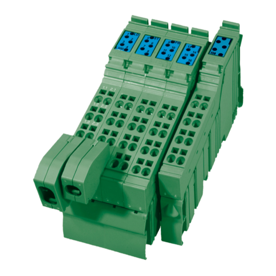
Deutschmann Automation GmbH & Co. KG 3 Basic unit LOCON 200 LOCON 200 is a modular cam control in industrial design for DIN-rail mounting. The basic device is made for the connection of an SSI-encoder (Singleturn or Multiturn), 13 bit parallel or for an incremental encoder for a counting area of up to 16 mio.... -
Page 13: Mechanical Installation Instructions
4 Mechanical installation instructions Installation LOCON 200 is a modular cam control in industrial design for DIN-rail mounting. Housing dimension The housing dimension of LOCON 200 results from the dimension of the basic unit and the dimensions of the connectors. Housing 5.3.15... -
Page 14: Mounting / Dismounting Of The Extension Module
The extension module is exclusively meant for the use at a LOCON 200. It is simply attached to the LOCON 200: No further tool is required to do so. By sequencing the potential and the bussignal connection between the components is automatically built up. -
Page 15: Connecting Lines Without Shield
Deutschmann Automation GmbH & Co. KG Mechanical installation instructions 4.4.1 Connecting lines without shield Connection example connector 5.3.15 Instruction manual LOCON 200 V. 4.3... -
Page 16: Connecting Shielded Lines
Mechanical installation instructions Deutschmann Automation GmbH & Co. KG 4.4.2 Connecting shielded lines Instruction manual LOCON 200 V. 4.3 5.3.15... -
Page 17: Grounding Clip
When using thin lines then the curvature of the grounding clip has to be directed towards the line (see pictures D - F), for thicker lines the other way round (see pictures A - C). 5.3.15 Instruction manual LOCON 200 V. 4.3... -
Page 18: Electrical Connections Locon 200
DIC- 1.4 / 2.4 Assignment X2 (encoder connection SSI + incremental) Ink 422 1.1 / 2.1 +24V_Enc. Gnd_Enc. +24V_Enc. Gnd_Enc. 1.2 / 2.2 Clk+ Clk- 1.3 / 2.3 Dat+ Dat- 1.4 / 2.4 Instruction manual LOCON 200 V. 4.3 5.3.15... -
Page 19: Assignment X3 + X4 (I/Os)
Preset, Out-Enable, external program selection and so on. Further information can be found in the chapter "Signal description LOCON 200". There are exceptions when it comes to a connection of a parallel absolute encoder or an incremental encoder with 24V-signals (see below). -
Page 20: Assignment Extension Module I/O 8
6, then the arrangement of inputs or outputs looks as follows: 1.1 / 2.1 O 17 O 18 1.2 / 2.2 O 19 O 20 1.3 / 2.3 O 21 O 22 1.4 / 2.4 I 23 I 24 Instruction manual LOCON 200 V. 4.3 5.3.15...
Need help?
Do you have a question about the LOCON 200 and is the answer not in the manual?
Questions and answers