
Related Manuals for DEUTSCHMANN AUTOMATION LOCON 200


Summary of Contents for DEUTSCHMANN AUTOMATION LOCON 200
- Page 1 Instruction manual Electronic cam control LOCON 200 Deutschmann Automation GmbH & Co. KG www.deutschmann.com | wiki.deutschmann.de...
- Page 2 Manual Art.-No. V3492E...
- Page 3 AUTOMATION reserves the right to carry out alterations to the described products in order to improve the reliability, function or design thereof. DEUTSCHMANN AUTOMATION only accepts liability to the extent as described in the terms and conditions of sale and delivery.
- Page 4 Deutschmann Automation GmbH & Co. KG Instruction manual LOCON 200 V. 4.6 13.11.18...
-
Page 5: Table Of Contents
Electrical connections LOCON 200 ....18 Front view LOCON 200 ......18 Assignment X1 (communication) . - Page 6 Operation mode of the shift register ..... 32 6.8.4 Logic functions of the LOCON 200-Out I/O8 ....33 6.8.4.1 Example for the use of a shift register .
- Page 7 10.3 Configuration and initialization ..... . 52 10.3.1 LOCON 200 parameter table ......52 10.3.2 Parameter description .
- Page 8 13 Order Code ......67 13.1 Cam control LOCON 200 ......67 13.1.1 Explanation of the order designation .
-
Page 9: Introduction
In such cases, the information applies to the entire model series. 1.1.3 Suggestions We are always pleased to receive suggestions and wishes etc. and endeavour to allow for these. It is also helpful if you bring our attention to any errors. 13.11.18 Instruction manual LOCON 200 V. 4.6... -
Page 10: From The Mechanical System To An Electronic System
The output is switched on between these points. Thanks to twenty years of experience, consistent further development and the use of ultra-mod- ern technology, DEUTSCHMANN AUTOMATION has now become one of the leading suppliers of electronic cam controls. Deutschmann Automation’s range of products A detailed and up-to-date overview of our product range can be found on our homepage at http://www.deutschmann.de. -
Page 11: Emc Directives For Products Of Deutschmann Automation
Deutschmann Automation GmbH & Co. KG EMC Directives for products of Deutschmann Automation 2 EMC Directives for products of Deutschmann Automation The installation of our products has to be carried out considering the relevant EMC directives as well as our internal instructions. -
Page 12: Basic Unit Locon 200
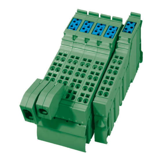
Deutschmann Automation GmbH & Co. KG 3 Basic unit LOCON 200 LOCON 200 is a modular cam control in industrial design for DIN-rail mounting. The basic device is made for the connection of an SSI-encoder (Singleturn or Multiturn), 13 bit parallel or for an incremental encoder for a counting area of up to 16 mio.... -
Page 13: Mechanical Installation Instructions
4 Mechanical installation instructions Installation LOCON 200 is a modular cam control in industrial design for DIN-rail mounting. Housing dimension The housing dimension of LOCON 200 results from the dimension of the basic unit and the dimensions of the connectors. Housing 13.11.18... -
Page 14: Mounting / Dismounting Of The Extension Module
The extension module is exclusively meant for the use at a LOCON 200. It is simply attached to the LOCON 200: No further tool is required to do so. By sequencing the potential and the bussignal connection between the components is automatically built up. -
Page 15: Connecting Lines Without Shield
Deutschmann Automation GmbH & Co. KG Mechanical installation instructions 4.4.1 Connecting lines without shield Connection example connector 13.11.18 Instruction manual LOCON 200 V. 4.6... -
Page 16: Connecting Shielded Lines
Mechanical installation instructions Deutschmann Automation GmbH & Co. KG 4.4.2 Connecting shielded lines Instruction manual LOCON 200 V. 4.6 13.11.18... -
Page 17: Grounding Clip
When using thin lines then the curvature of the grounding clip has to be directed towards the line (see pictures D - F), for thicker lines the other way round (see pictures A - C). 13.11.18 Instruction manual LOCON 200 V. 4.6... -
Page 18: Electrical Connections Locon 200
Modbus RS485 (optional) Modbus RS485 (optional) Modbus RS232 (optional) 1.1 / 2.1 +24V +24V +24V 1.2 / 2.2 n. c. n. c. n. c. n. c. n. c. n. c. 1.3 / 2.3 485+ 485- 1.4 / 2.4 Instruction manual LOCON 200 V. 4.6 13.11.18... -
Page 19: Assignment X2 (Encoder Connection Ssi + Incremental)
Preset, Out-Enable, external program selection and so on. Further information can be found in the chapter "Signal description LOCON 200". There are exceptions when it comes to a connection of a parallel absolute encoder or an incremental encoder with 24V-signals (see below). -
Page 20: Assignment Extension Module I/O 8
6, then the arrangement of inputs or outputs looks as follows: 1.1 / 2.1 O 17 O 18 1.2 / 2.2 O 19 O 20 1.3 / 2.3 O 21 O 22 1.4 / 2.4 I 23 I 24 Instruction manual LOCON 200 V. 4.6 13.11.18... -
Page 21: Signal Description Locon 200
Signal to present the status of the cam control Incremental output* Two outputs to generate an A/B-signal Not connected *) These signals are distributable on the I/Os as desired. *) These signals have to be applied for at least 1ms! 13.11.18 Instruction manual LOCON 200 V. 4.6... -
Page 22: External Program Selection
200 ms. The following steps are required if, for example, program 7 (binary 00000111) is to be activated: 5.6.1 Applying the corresponding voltages Volt Binary PROG_NR128 PROG_NR64 PROG_NR32 PROG_NR16 PROG_NR8 PROG_NR4 PROG_NR2 PROG_NR1 Instruction manual LOCON 200 V. 4.6 13.11.18... -
Page 23: Generating The Acceptance Edge
If pin "PROG_START" is permanently wired to 24V, LOCON accepts the program applied externally each time the unit is powered up. Installation and initiation of LOCON 200 The screw-type plug connectors of the LOCON must be plugged in and unplugged only with the power supply disconnected!!! 5.7.1... -
Page 24: Connection Of The Inputs And Outputs
For switching please use a suitable tool and carefully shift the microswitch to the left or the right. Attach a new sticker with the corresponding mark. Instruction manual LOCON 200 V. 4.6 13.11.18... -
Page 25: Interface Switch (Firmware V3.0 And Higher)
All "DIC+" signals are interconnected and all "DIC-" signals are interconnected on the bus. The signals are not reversed. However, it must be ensured that the potential differences between the DICNET users do not exceed 7V. Please always follow the information in chapter "RS485 link (DICNET)"! 13.11.18 Instruction manual LOCON 200 V. 4.6... -
Page 26: Configurations Locon 200
After uploading the basic configuration from the device a wizard is started via the function “Reconfigure“ that leads the user through the configuration menu. With it a predefined sequence is kept, where the LOCON 200 can be adjusted to the relevant requirements step-by-step. -
Page 27: Possible Error Messages On The Configuration
Based on the basic device the encoder type is selected first. The following parameters depend on the chosen encoder type. Therefore it is required to keep the predefined order of the configu- ration tree. 13.11.18 Instruction manual LOCON 200 V. 4.6... -
Page 28: Configuration Example
0 = None 1 = Blockwise Idle time type 0x0032 2 = Bitwise 3 = Blockwise on/off 4 = Bitwise on/off Note: After the configuration the device has to be restartet. Instruction manual LOCON 200 V. 4.6 13.11.18... -
Page 29: Parameter Table
PNR_AKTIV_STATUS 0x0057 PNR_PROC_LOAD 0x0058 Processor utilization PNR_ENABLE_OPTION 0x0059 Release of options PNR_TEACH_IN_ZEROPOINT 0x0060 Teach-in zero offset PNR_ENABLE_TESTMODE 0x005B With 0x1234 -> Switch to testmode PNR_ERROR_QUIT 0x0060 Error quit through Modbus 0 -> 1 13.11.18 Instruction manual LOCON 200 V. 4.6... -
Page 30: Pnr_Encoder_Typ - Encoder Type
3. Multiturn with a resolution of 25 bit (8192 x 4096). Please note that the evaluation here takes place as for a 24 bit-encoder - that is 4096 x 4096. The SSI-interface‘s assignment can be found in chapter "Electrical connections LOCON 200". Instruction manual LOCON 200 V. 4.6... -
Page 31: Incremental Encoder
Example: A plant is equipped with an incremental encoder (resolution 8192 inc./rev.) and a LOCON 200 (counting area 8192). The application comes to an end after four revolutions of the encoder. -
Page 32: Logic Functions (Optional)
• A 32-bit shift register The outputs and markers may be inverted. The logic of the LOCON 200 - Basis can not be linked with the LOCON 200-Out I/O8. Special instruction for PROFIBUS-interface: For an operation via the PROFIBUS-interface the logic inputs can be read in either via the I/Os or the PROFIBUS. -
Page 33: Logic Functions Of The Locon 200-Out I/O8
• A 32-bit shift register The outputs and markers may be inverted. The logic of the LOCON 200-Out I/O8 can not be linked with the LOCON 200-Basis. Special instruction for PROFIBUS-interface: For an operation via the PROFIBUS-interface the logic inputs can be read in either via the I/Os or the PROFIBUS. -
Page 34: Count Cam
Afterwards an update of the outputs only takes place if the encoder’s direction of rotation corre- sponds to the programmed direction of the output and a cam edge (switch on- or switch off-point) is present. Instruction manual LOCON 200 V. 4.6 13.11.18... -
Page 35: Run-Control-Output
6.12 Dynamical zero offset Besides the static zero offset (NPV) a dynamical zero offset can be programmed in LOCON 200. During operation through an initiator signal the position can be offset to „0“ at any position of the encoder via an input that can be mapped as desired. -
Page 36: Offline Programming
With the rising edge at the teach-in-input (transition 0V -> 24V) the cam’s switching point is defi- ned, with a falling edge (transition 24V -> 0V) the cam’s release operating point is defined. Swit- ching points and release operating points are the positions, that are read-in by LOCON 200 at the time of the edge change. -
Page 37: Mapping
Configurations LOCON 200 6.19 Mapping In LOCON 200 the following input and output signals (see also chapter "Signal description LOCON 200") can be distributed as desired among the I/Os of the basic device via a mapping in WINLOC32: Function Significance... -
Page 38: Networking Terminals With Cam Controls And Pcs
UNITRONIC -BUS LD cable 2 x 2 x 0.22, available on a drum from LAPP KABEL in Stuttgart, or by the metre from DEUTSCHMANN AUTOMATION. Instruction manual LOCON 200 V. 4.6 13.11.18... -
Page 39: Earthing, Shielding
DICNET up to a certain extent. Wherever possible, the RS232 interface should be used only for temporary connections (e. g. for connecting a PC). 13.11.18 Instruction manual LOCON 200 V. 4.6... -
Page 40: Connection Examples
The bus termination resistor must be activated on both units. Consequently, in the case of simple wiring with a LOCON and an external operator control panel, it is the obvious choice to use the same 24V supply for both units. Instruction manual LOCON 200 V. 4.6 13.11.18... -
Page 41: Rs232 Link Locon - Term
The two ground potentials must be connected Picture 5: RS232 link Terminal - LOCON The presented devices exemplary stand for Deutschmann terminals and cam controls of the series LOCON / ROTARNOCK respectively. 13.11.18 Instruction manual LOCON 200 V. 4.6... -
Page 42: Dicnet Link Locon-Term-Pc
PC is made at a serial port COMx - see the illustration below DICNET+ DICNET+ DICNET- DICNET- Terminal LOCON COMx Picture 6: Link DICNET bus to PC The presented devices exemplary stand for Deutschmann terminals and cam controls of the series LOCON / ROTARNOCK respectively. Instruction manual LOCON 200 V. 4.6 13.11.18... -
Page 43: Short Instuction
Deutschmann Automation GmbH & Co. KG Networking terminals with cam controls and PCs Short instuction 13.11.18 Instruction manual LOCON 200 V. 4.6... - Page 44 A more detailed description on how the device is programmed via TERM 24 can be found in the instruction manual for ”LOCON 24 / 48 / 64”. The described ways of proceeding for LOCON 24 / 48 / 64 also apply for TERM 24. Instruction manual LOCON 200 V. 4.6 13.11.18...
-
Page 45: Locon 200 With Modbus
LOCON 200-MB through the Modbus-master. There is the possibility to change this mode so that the LOCON 200-MB saves the cam values in the EEROM permanently. To do so the parameter "DataInRamOnly" in the configuration area has to be set to “No“... - Page 46 A maximum of 32 cams each output can be programmed! ------------------------------------------------------------------------------------------------------------------------------- Process data - Example: The process data “Position“ are supposed to be read out from the L200- Modbus with the Modbus address = 1: Instruction manual LOCON 200 V. 4.6 13.11.18...
- Page 47 00 Parameter H 1. byte 00 Parameter H 2. byte 00 Parameter L 1. byte 01 Parameter L 2. byte CRC ------------------------------------------------------------------------------------------------------------------------------- Cams - Example: Setting the 1. cam on output 1 from position 1000 - 2000. 13.11.18 Instruction manual LOCON 200 V. 4.6...
- Page 48 02 Length in words L 04 Length in bytes CRC 00 Pos Off H 1. byte 00 Pos Off H 2. byte 07 Pos Off L 1. byte D0 Pos Off L 2. byte Instruction manual LOCON 200 V. 4.6 13.11.18...
-
Page 49: Angle-Time-Cam At Locon 200 With Modbus
Modbus RTU specification. Angle-time-cam at LOCON 200 with Modbus The LOCON 200 with Modbus supports a single-turn application with a maximum encoder resolution of 13 bits. This corresponds to an input and output value of a maximum of 8192 increments. -
Page 50: Locon 200 With Profibus
CD. PROFIBUS Slave ID The PROFIBUS-address (ID) at the LOCON 200 is set through the rotary coding switches at the device’s underside, through WINLOC32 or the PROFIBUS-Master. If an ID between 1...7E (126 dec.) is set this address is always valid for the device. -
Page 51: Commissioning And Self-Test
Please refer to chapter "Error messages" for the significance of this number and the actions required. Moreover, the optional Run-Control relay remains in dropped-out condition and the correspond- ing status LED "Run Error" lights. 13.11.18 Instruction manual LOCON 200 V. 4.6... -
Page 52: Self-Test Of The Cam Control
Ex: DICNET with bus termination (x = DICNET ID) Dx: DICNET without bus termination (x = DICNET ID) Angle-time cam No, yes No, yes Direction cams Both Both, positive and negative direction Both, positive and negative direction Instruction manual LOCON 200 V. 4.6 13.11.18... -
Page 53: Parameter Description
NET bus and with which, for example, it is addressed by WINLOC32 or communicates with TERM 6. This value can be changed only with the rear-panel DIP switch and not in the menu. 13.11.18 Instruction manual LOCON 200 V. 4.6... -
Page 54: Zero Offset (Only For Absolute Encoders)
The following restriction applies for the MT-configuration: If „real value’ is not equal to „fictitious value“ (i. e. if you work with fictitious counting areas or encoder resolutions), then both values must not exceed 65535. Instruction manual LOCON 200 V. 4.6 13.11.18... -
Page 55: Technical Details
In case a higher current is required, it is possible to insert a segment terminal (designation: seg- ment terminal for LOCON 200, art.-no. V3694) between the basic device and the extension module (also between the single extension modules). With this segment terminal another 8A can be fed. -
Page 56: Locon 100 Memory Structure
1 logic record 1 data record 1 output name (max. 30 characters) 5 data records (6 characters/data record) 11.4 LOCON 200 memory structure - Out I/08 (expansion module) Memory size Number of data records 8 kbyte 232 data records 8 bytes are required for each data record. The remaining data records are required by the firm- ware. -
Page 57: Nt Module
11.5 NT Module The NT module for LOCON 200-Out I/O8 is a power supply that must be used for a configuration level step of more than 8 LOCON 200-Out I/O8 expansion modules. The NT module must be inserted immediately after the LOCON 200 basic unit. Nothing can be connected to the NT module itself. -
Page 58: Switching Accuracy Of The Deutschmann Cam Controls
- INK (High speed version) = 84µs (see High speed version) - other encoder types = 500µs = ST: 0.6µs/bit -> 13 data bits + 3 bits pause = 16 bits x 0.6µs = 9.6µs ~ 10µs comm. Instruction manual LOCON 200 V. 4.6 13.11.18... -
Page 59: Function Of The Idle Time Compensation
13.11.18 Instruction manual LOCON 200 V. 4.6... -
Page 60: Time-Controlled Idle Time Compensation
The transmission baud rate is 312.5 kbaud with a length of 11 bits/byte. A maximum of 127 users may be operated on one bus, whereby data packets of maximum 14 bytes per cycle can be sent. Instruction manual LOCON 200 V. 4.6 13.11.18... -
Page 61: Modbus
"Modicon Modbus Protocol Reference Guide" from the company Modicon. 11.14 Communication interface DEUTSCHMANN AUTOMATION encourages the use of cam controls with remote control and display unit in order to meet market requirements. Since different combinations of cam control and terminal have been required repeatedly, specific... -
Page 62: Coding Device Numbers
11.15 Coding device numbers The device number is set in hexadecimal code on the rotary switch. The following assignment applies: ID HIGH ID LOW Display Device number Binary coding Display Device number Binary coding Instruction manual LOCON 200 V. 4.6 13.11.18... -
Page 63: Error Messages
EEPROM full All data records in the EEPROM are used. Either you must remove cams no longer required or the unit must be equipped with a higher-capacity mem- ory card (LOCON 32 only). 13.11.18 Instruction manual LOCON 200 V. 4.6... - Page 64 Error programming a direction cam Direction cam prohibited PLL-error Counting area too high for speed Area of the transferred cams is wrong All outputs are switched briefly to 0V when error 31 is acknowledged. Instruction manual LOCON 200 V. 4.6 13.11.18...
-
Page 65: Error Number 100
A prohibited device configuration been saved (e. g. absolute configuration) encoder with 127 increments resolution). Carry out a general reset Encoder error (only when encoder See chapter "Encoder monitoring". monitoring is on) SSI Timeout error SSI Gray code error 13.11.18 Instruction manual LOCON 200 V. 4.6... -
Page 66: Error Number 200-299 (Terminal Error)
Reduce to 3 terminals 3 allowed) Max. 1 external terminal in the case of multiple-axis version of the LOCON 32 Internal error Unknown command Internal error Checksum error detected by the cam Internal error control Instruction manual LOCON 200 V. 4.6 13.11.18... -
Page 67: Order Code
13.1 Cam control LOCON 200 13.1.1 Explanation of the order designation LOCON 200 is available in three different versions. 1. LOCON 200 with switchable RS232/RS485 (DICNET)-interface 2. LOCON 200-PB PROFIBUS- and RS232-interface 3. LOCON 200-MB with switchable RS232/RS485 (Modbus-RTU)-interface 13.2 Scope of delivery 13.2.1... -
Page 68: Servicing
The more precise your information and error description, the more precisely we can check the possible causes. Devices, that are sent in without an error description undergo a standard test. You have to bear the costs for that test even though no defect was found. Instruction manual LOCON 200 V. 4.6 13.11.18... -
Page 69: Internet
14.2 Internet The current software WINLOC32 is available for download from our Internet-homepage www.deutschmann.com. There you can also find topical information on Deutschmann products, instruction manuals and a list of our distribution partners. 13.11.18 Instruction manual LOCON 200 V. 4.6... - Page 70 Servicing Deutschmann Automation GmbH & Co. KG Instruction manual LOCON 200 V. 4.6 13.11.18...
- Page 72 Servicing Deutschmann Automation GmbH & Co. KG Instruction manual LOCON 200 V. 4.6 13.11.18...
Need help?
Do you have a question about the LOCON 200 and is the answer not in the manual?
Questions and answers