Table of Contents
Advertisement
Quick Links
Tele File Kit
For HDW-700/700A
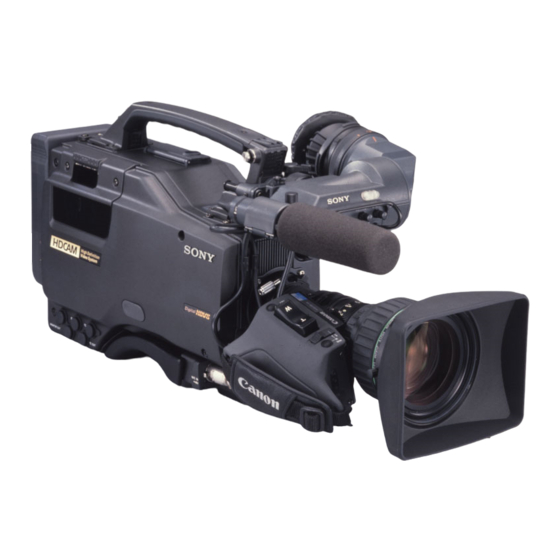
HDW-700
TELE FILE
本キットを
に取り付ける際または取り付け後
機能を操作する際、お手持ちのメ
ンテナンスマニュアルまたはオペレーションマニュアルと併せてご使用ください。
When you install this kit to the HDW-700/700A or operate the TELE FILE functions, please
refer to this manual together with the maintenance manual and operation manual in your
possession.
Advertisement
Chapters
Table of Contents

Summary of Contents for Sony HDW-700
- Page 1 Tele File Kit For HDW-700/700A HDW-700 TELE FILE 本キットを に取り付ける際または取り付け後 機能を操作する際、お手持ちのメ ンテナンスマニュアルまたはオペレーションマニュアルと併せてご使用ください。 When you install this kit to the HDW-700/700A or operate the TELE FILE functions, please refer to this manual together with the maintenance manual and operation manual in your possession.
-
Page 3: Table Of Contents
目次 日 概要 ........................2(JP) 本 取り付け ......................... 3(JP) 語 1. DC-DCコンバーターASSY/カセッ ト コンパー ト メ ン トASSY/ イ ンサイ ドパネルを取り外す ..............3(JP) 2. アンテナシー トの取り付け ................3(JP) 3. SY-247 基板の交換 ..................4(JP) 4. DC-DCコンバーターASSY の交換 ..............4(JP) CCM-33B 基板の調整 ..................6(JP) Tele File機能を操作する ..................7(JP) 1(JP) - Page 4 概要 本キッ ト はHDW-700にTele-Fileシステムを取り付けるための必要 部品を集めたキッ トです。 Tele-Fileシステムを動作させるには、この他にテクニカルメモ HDVM 00-328による ソフ ト ウェアのバージ ョ ンアップが必要です。 以下の部品がキッ ト(A-8327-316-A)に含まれています。 名称 部品番号 員数 CCM-33B COMPL-NC A-8320-065-B FL-260フ レキシブル配線板 1-671-386-11 小物ハーネス (CCM) 1-959-170-11 パネル支柱 (B) 3-192-607-31 ス ト ッパー板 3-614-802-04 アンテナシー ト(A) 3-614-804-01 アンテナシー ト(B) 3-614-805-01 アンテナシー ト(C) 3-614-806-01 ナイ...
-
Page 5: 取り付け
取り付け 以下の項目1〜4の手順に従い、 本キッ トの部品をHDW-700本体 内側 に取り付けます。 1. DC-DC ASSY コンバーター /カセットコン P1.4 + × ストッパー板 ASSY パートメント /インサイドパネルを取 ストッパー板 り外す ステージ ネジ5 本を充分にゆるめ、 アウ トサイ ドパネルを取り外す。 ◆ 詳しく は、メ ンテナンスマニュアル Part 1 2-3 項をご覧く ださい。 ASSY 側板 DC-DCコンバーターASSYを取り外す。 (ネジ無し) ASSY ステージ ネジ3本を取り外し、 カセッ ト コンパー ト メ ン トASSYを取り外す。... -
Page 6: Sy-247 基板の交換
取り付け 3. SY-247 基板の交換 FL-260フ レキシブル配線板を、 DC-DCコンバーターASSY の シール ドケース とシール ド板の間に通す。 イ ンサイ ドパネルを取り外し、 以下の手順でSY-247基板を交換します。 FL-260 フレキシブル配線板 DC-DC コンバーター ASSY CN-1457 基板を取り外し、取り付けられているSY-247 基板 (suffix=A)をキッ トの SY-247 基板(suffix=B)と交換する。 ◆ 詳しく は、メ ンテナンスマニュアル Part 1 2-4 項をご覧く ださい。 CN-1457 基板を元の位置に取り付ける。 イ ンサイ ドパネルを元の位置に取り付ける。 シールドケース 4. - Page 7 CCM-33B 基板を、 ネジ (+ PSW2.6×6) 2 本でパネル支柱 FL-260フレキシブル配線板を CCM-33B 基板のコネクター (B)2 本に固定する。 CN1に接続する。 パネル支柱 メモリ ーラベル MLB-1M-100が貼り付けられたカセ ッ ト を挿入 し、下図の矢印方向に、 カチッ と音がするまで移動する。 小物ハーネス (CCM) CCM-33B 基板 RE-140 基板 レバー + PSW2.6 × DC-DC ASSY コンバーター FL-260フレキシブル配線板を、 DC-DCコンバーターASSY の 次ページの 「CCM-33B基板の調整方法」 に従い、 CCM-33B シール...
-
Page 8: Ccm-33B 基板の調整
取り付け CCM-33B SY-247基板のCN1とパソコン をRS-232イ ンターフェース治具 基板の調整 で 接続する。 CCM-33B 基板の調整は以下の手順で行います。 1) IBM PC/ATパソコン、 またはNEC PC9800シリ ーズパソコン オシロスコープを以下のよう に設定する。 ◆ 設定については、 メ ンテナンスマニュアルPart 2 Volume1 5-6項 VERTICAL をご覧く ださい。 CH1 : 5V/DIV, DC 2) IBM PC/AT パソコ ン用(9 pin) CH2 : 5V/DIV, DC • RS-232イ ンターフェースケーブル:HJ-012/J-6510-120-A MODE : CH2 INVERT, ADD, 20MHz BW LIMIT=OFF • 治具ケーブル(PCnHJ-012) :HJ-PC9/J-6510-120-2 HORIZONTAL • 治具ケーブル(HJ-012nSY247) :CN-HJ/J-6510-110-3 20nSEC/DIV NEC PC-9800シ... -
Page 9: Tele File機能を操作する
Tele File 機能を操作する HDW-700でTele File機能を使う には、 以下の手順で操作します。 HDW-700に挿入されたカセ ッ ト にメモリ ーラベル MLB-1M-100 (別 売り)が貼り付けられている場合、 メモリ ーラベルに記録開始タイ ム コー ド、 シ ョ ッ トマーク を記録するこ とができます。 メモリ ーラベル MLB-1M-100を貼り付けたカセッ ト を入れる。 VTR STARTボタ ン、 またはレンズのVTRボタ ンを押す。 記録開始と同時に、 記録開始時のタイ ムコー ドがメモリ ーラベ ルに記録されます。 撮影をしながら、 レンズのRETボタ ンを押す。... - Page 11 Table of Contents Overview ..................... 2(US) 1. Removing the cassette compartment a’ssy, DC-DC converter a’ssy and inside panel ..............3(US) 2. Installation of the antenna sheets ..........3(US) 3. Replacement of the SY-247 board ........... 4(US) 4. Installation of the DC-DC converter assembly ......4(US) Adjustment of CCM-33B board ...........
-
Page 12: Overview
Overview This kit is required for installation of Tele-File system to HDW-700/700A. To start up this system, be sure to perform the software upgrade in accordance with Technical Memo HDVM 00-328. The following three kinds of kits exist. Kit 700-1 (A-8327-314-A) for HDW-700 : Serial No. -
Page 13: Removing The Cassette Compartment A'ssy, Dc-Dc Converter A'ssy And Inside Panel
Installation Install the parts of the kit to the HDW-700/700A according to the following procedures of item 1 to 4. Inside 1. Removing the cassette compartment a’ssy, DC-DC converter a’ssy and inside panel Stopper plate +P1.4×2.5 Stopper plate Loosen the 5 screws, and remove the outside panel. -
Page 14: Replacement Of The Sy-247 Board
Install the DC-DC converter assembly according to the following procedure. DC-DC converter ass’y For HDW-700 with serial No. 10001 to 10055 or 90001 to 90004 Use the new DC-DC converter assembly of the kit. Pass the FL-260 flexible board between the shield case and shield plate of the DC-DC converter For HDW-700 with serial No. - Page 15 Install the DC-DC converter assembly. Adjust the CCM-33B board according to “Adjusting CCM-33B board” (next page). DC-DC converter a’ssy For details, refer to Maintenance Manual Part2 Volume1 7-5. FL-260 flexible board Disconnect the FL-260 flexible board and the CN1 connector of the CCM-33B board. Remove the DC-DC converter assembly.
-
Page 16: Adjustment Of Ccm-33B Board
Installation Pass the FL-260 flexible board between the shield Adjustment of CCM-33B board case and shield plate of the DC-DC converter assembly. (Refer to the figure of step 2.) The CCM-33B board can be adjusted with the following procedure. Install the DC-DC converter assembly, and connect the FL-260 flexible board to the CN1 Set up the oscilloscope as follows. - Page 17 Adjust by an adjustment driver. Note Confirm that “OK” is displayed on the monitor of the personal computer. Turn off the power of the HDW-700/700A, then remove the RS-232 interface jig. Adjustment point : CT1 Specification : A=MAX (10Vp-p or more) 5.0 V...
-
Page 18: Operation Of Tele File Functions
Operation of TELE FILE Functions Operation of TELE FILE Menu To operate the Tele File functions with the HDW-700/ 700A, follow the procedure below. When the cassette tape with the optional memory label MLB-1M-100 is inserted in the HDW-700/700A, it is... - Page 19 The material contained in this manual consists of information that is the property of Sony Corporation and is intended solely for use by the purchasers of the equipment described in this manual. Sony Corporation expressly prohibits the duplication of any...
- Page 20 Sony Corporation Communication System Solutions Network Company Printed in Japan Tele-File Kit 2000.11.13 2000 3-205-176-01(1)


Need help?
Do you have a question about the HDW-700 and is the answer not in the manual?
Questions and answers