Table of Contents
Advertisement
Quick Links
Advertisement
Table of Contents

Subscribe to Our Youtube Channel
Related Manuals for Giada F110D


Summary of Contents for Giada F110D
- Page 2 The copyright of this manual belongs to Shenzhen JEHE Technology Development Co., Ltd. (Giada, JEHE’s global brand) and all rights are reserved. The company reserves the right to change this manual at any time without notification. Specifications here are for reference only, please take the real product as standard.
-
Page 3: Table Of Contents
Table of Contents 1. Product Introduction ....................3 2. Interface Description and Hardware Specifications ..........3 2.1 Interface Description .................... 3 2.2 Hardware Specifications ..................4 3. Accessories Installation Steps ................. 5 3.1 Memory Installation ..................... 6 3.2 WiFi/BT(Half-size Mini-PCIe) Installation ............7 3.3 MSATA Installation .................... - Page 4 4.2.9 Miscellaneous Configuration ..............21 4.2.10 Network Stack Configuration ..............22 4.2.11 CSM Configuration ................. 23 4.3 Chipset ........................ 24 4.3.1 North Bridge ....................25 4.3.2 South Bridge ....................26 4.4 Security ......................28 4.5 Boot Menu ......................29 4.6 Save & Exit ......................31 5.
-
Page 5: Product Introduction
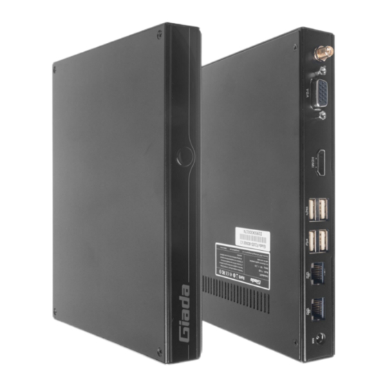
1. Product Introduction Based on Intel ® Bay Trail platform, the player supports one HDMI and one VGA display outputs. The player is suitable to be applied in mainstream digital signage applications. 2. Interface Description and Hardware Specifications 2.1 Interface Description Front I/O Port Rear I/O Port Left I/O Port... -
Page 6: Hardware Specifications
Right I/O port 2.2 Hardware Specifications F110D F110D-BD000 F110D-BB000 Intel ® Celeron J1900 Intel ® Celeron N2807 Processor Frequency 2.00GHz (Up to 2.42GHz) 1.58GHz (Up to 2.16GHz) BIOS AMI Source Code Chipset Type DDR3L-1333MHz Memory Socket 1 x SO-DIMM Max Capacity Intel®... -
Page 7: Accessories Installation Steps
Power Type DC-IN Power Input Voltage 19V/2.1A Construction Metal Mounting Desk/VESA Mounting(JZ183) Mechanical Dimension 189.6mm x 148.3mm x 26mm (W x D x H) Color Black Operating 0℃ ~ 40℃ ( 32 ℉ ~ 104 ℉ ) at 0.7m/s Air Flow Environment Temperature Relative Humidity... -
Page 8: Memory Installation
3.1 Memory Installation This product only supports DDR3L SO-DIMM memory modules. 1. Locate the SO-DIMM slot on the board. 2. Gently insert the module into the slot in a 45-degree angle. 3. Carefully push down the memory module until it snaps into the locking mechanism. - 6 -... -
Page 9: Wifi/Bt(Half-Size Mini-Pcie) Installation
3.2 WiFi/BT Installation (Half-size Mini-PCIe) 1. Plug the WIFI module into half-size mini PCIE slot. 2. Secure the module to the carrier by tightening up the screw. 3. Connect the black cable to Main and grey cable to AUX. Install the antenna. 3.3 MSATA Installation 1. -
Page 10: Sata Installation
3.4 2.5" SATA Installation 1. Plug 2.5” SATA into the slot. 2. Tighten up the three screws from another (bottom) side 3. Remove the clear membrane of the thermal pad and paste the pad on the 2.5” SATA. 4. Remove the blue membrane of the thermal pad. - 8 -... -
Page 11: Bios Setup
The descriptions relating to BIOS setup in this Manual is for reference only since the BIOS version of the product might be upgraded. Giada provides no guarantee that all the contents in this Manual are consistent with the information you acquired. - Page 12 B. Function Keys definitions Hot Key Description ↑ (Up key) Move to the previous item ↓ (Down key) Move to the next item ← (Left key) Move to the left item → (Right key) Move to the right item Exit the current interface Page Up Change the setup state, or add the values Page Down...
- Page 13 Fig 1 1) Main (standard CMOS setup) This item is used for setting the date and time. 2) Advanced (advanced BIOS setup) This item is used for setting the advanced functions provided by BIOS, such as specifications of PCIe facilities, CPU, HDD, etc.
-
Page 14: Main (Standard Cmos Setup)
4.1 Main (Standard CMOS Setup) 1) System time (hh:mm:ss) Use this item to set the time for the computer, with the format as “HH / MM / SS”. 2) System date (mm:dd:yy) Use this item to set the date for the computer, with the format as “week, MM / DD / YY”. - 12 -... -
Page 15: Advanced (Advanced Bios Setup)
4.2 Advanced (Advanced BIOS Setup) 4.2.1 Trusted Computing - 13 -... -
Page 16: Lan Configuration
4.2.2 LAN Configuration 4.2.3 Wakeup Configuration - 14 -... -
Page 17: Super Io Configuration
Wake Configuration Menu Description Enable or disable System wake on alarm event. Select FixedTime, system will wake on the Wake system from RTC hr::min::sec specified. Select DynamicTime, System will wake on the current time + Increase minute(s). Enabled or Disabled Wake Up by USB KB/MOUSE from S3 Status. -
Page 18: Super Io Hardware Monitor
4.2.5 Super IO Hardware Monitor Super IO Hardware Monitor Menu Description PC Health Monitor Status SYS temperature The Current System temperature CPU temperature The Current CPU temperature - 16 -... -
Page 19: Cpu Configuration
4.2.6 CPU Configuration - 17 -... - Page 20 CPU Configuration Menu Description Socket 0 CPU Information Socket specific CPU information. CPU Thermal Configuration Enabled/Disabled Digital Thermal Sensor. Limit CPUID Maximum Disabled for windows XP Enable/Disable Thermal Monitor. Thermal Monitor Enabled. This item is enabled by default. Disabled.
-
Page 21: Ppm Configuration
4.2.7 PPM Configuration CPU Configuration Menu Description This option controls Max C state that the Processor CPU C State Report will support. O0ix Enabled/Disabled CPU S0ix state. - 19 -... -
Page 22: Ide Configuration
4.2.8 IDE Configuration IDE Configuration menu Description SATA Controller. Serial-ATA(SATA) Disabled. Enabled: The SATA controller is enabled by default. Disabled SATA Test Mode Enabled Set SATA Speed SATA Speed Support Gen2 Gen1 Current SATA ODD device list ... -
Page 23: Miscellaneous Configuration
IDE Configuration menu Description Enable/Disable Serial-ATA Port0 Serial-ATA Port 0 Enabled Disabled Enable/Disable Serial-ATA Port0 Hotplug function SATA Port0 HotPlug Enabled Disabled Enable/Disable Serial-ATA Port1 Serial-ATA Port 1 Enabled Disabled Enable/Disable Serial-ATA Port1 Hotplug function SATA Port1 HotPlug Enabled ... -
Page 24: Network Stack Configuration
Miscellaneous Menu Description It can be set according to user's needs. If using window OS, OS Selection must be windows. If using Linux, OS Selection must be Android or Linux. OS Selection Windows 7. Windows 8.X Android 4.2.10 Network Stack Configuration Network stack Menu Description... -
Page 25: Csm Configuration
Network stack Menu Description The user can enable or disable IPV4 PXE Boot support. If disabled, IPV6 PXE boot option will not be created. Ipv6 PXE Support Enabled. Disabled.IPV6 PXE support is disabled by default. It means the wait time to press ESC key to abort the PXE PXE boot wait time boot. -
Page 26: Chipset
Advanced Menu Description Storage ROM Boot. Do not launch: Do not Boot. Storage UEFI: It will support UEFI mode storage ROM. Legacy: It will support legacy mode storage ROM. Video ROM Boot. Video UEFI: It will support UEFI mode Video ROM. ... -
Page 27: North Bridge
4.3.1 North Bridge - 25 -... -
Page 28: South Bridge
Chipset menu Description North Bridge Configuration Intel IGD Configuration Enabling GOP Driver will unload VBIOS; Disabling it will load GOP Driver VBIOS. IGD Turbo Enabled Enable/Disable IGD Turbo. 4.3.2 South Bridge - 26 -... - Page 29 Chipset menu Description South Bridge Configuration - 27 -...
-
Page 30: Security
Chipset menu Description USB Configuration USB OTG Support Enabled/Disabled USB OTG support. VBIOS should be On in HOST mode. It should be OFF in USB VBUS OTG device mode. XHCI MODE Mode of operation of XHCI controller. USB LINK Power Management Enable/Disable USB2 Link Power Management. -
Page 31: Boot Menu
If this function is selected, the following information will appear: Enter New Password hhhhhh Then enter a password which is no more than eight characters and press <Enter>. BIOS will require to enter the password again. Once you enter it again, BIOS will save the set password. Once the password item is enabled, you will be required to enter the password every time before the system entering to the setup program of BIOS. - Page 32 Boot Item Description Boot Configuration This item is used to set the waiting time of entering the operation system. During the BIOS post, if user doesn't press Setup Prompt Timeout the keyboard, it won't respond unless you reboot the BIOS. The Setup Prompt Timeout is 3s by default.
-
Page 33: Save & Exit
4.6 Save & Exit Save Exit Item Description Save Options Save Changes and Reset Save all changes and exit Discard Changes and Reset Give up the settings and exit. Save Changes and Reset Reset the system after saving the changes. Discard Changes and Reset Reset system setup without saving any changes. -
Page 34: Jahc Introduction
5. JAHC Introduction JEHE Active Hardware Control (JAHC) management system includes both hardware Micro Control Unit (MCU) and software (JAHC Technology Manager). It can support following functions: 1. Automatically boot up when power on. It is controlled by the Micro Control Unit (MCU) chip. 2. -
Page 35: Jahc Software
Supported operation system: Windows 10 64bit, Linux 64bit. How to install JAHC software: Please download the JAHC.EXE from Giada website: www.giadatech.com, then follow up below steps: Double-click the JAHC.EXE file, the setup wizard will pop up, select destination location and click [Next] button to continue the installation. - Page 36 b. Click [Next] button to continue the installation. Select [Create a desktop shortcut] and click [Next] button. - 34 -...
- Page 37 d. Click [Install] button to continue the installation. - 35 -...
-
Page 38: Startup & Shutdown Time Setup
Click [Finish] button to finish the installation. You can select [Launch JAHC] to run the software automatically after finishing the installation. Notice: The JAHC will be added into boot item when it is installed. It will start up when system boot up. 5.2.3 Startup &... - Page 39 One week as a circle, maximum 3 schedules per day. Select each schedule to set up the resume time and shutdown time. Click [Confirm] button to launch the schedule. After finishing the setup, the menu window will notice the resume time and shutdown time. Caution: If the interval from shutdown time to next resume time is less than 3 minutes, the system will not shut down Click [Cancel] button to restore the time settings and cancel the shutdown status.
-
Page 40: Watchdog Api And Instruction
You can click [Delay] button and set up the time to delay the shutdown or click [Cancel] button to cancel the shutdown. 5.3 Watchdog API and Instruction Please contact Giada FAE (email:support@giadatech.com) for watchdog API software and instruction. - 38 -... - Page 41 - 39 -...
Need help?
Do you have a question about the F110D and is the answer not in the manual?
Questions and answers