Advertisement
Giada i200 Series Assembly Guide
Thank you for choosing Giada product. In such an epoch of PC development, we launched Giada
Barebone which is characterized by the mini shape, vogue and ultra-thin structure, environment
friendly, Giada will allow you to undergo new experience in the field. This Guide shows you how to
do installation and uninstallation quickly and correctly.
WARNING:
This motherboard contains static-sensitive components and should be handled with care. Failure to employ
adequate anti-static measures can cause partial or complete device failure, performance degradation, or
reduced operating life. The battery must be replaced with the correct type of lithium cell battery; otherwise
there is a risk of damage to the motherboard. To avoid electrostatic discharge (ESD) damage upon handling
this product, it is strongly recommended that you wear a grounded wrist strap or other static dissipating
device.
CONTENT:
Memory, SSD, Wireless Module and MINI SIM Card installation
Remark:
The picture shown in this document is only a model of our series products, the actual
object is subject to change depends on the model you purchase.
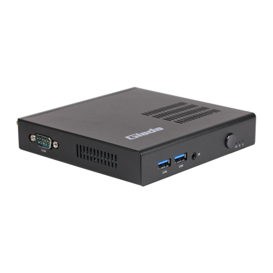
Part 1. Appearance
The Front Panel.
The Back Panel.
USB3.0 USB3.0
1x 3.5mm jack for extended infrared
sensor and extended Power Switch
DC-IN
Display Port
For antenna
Clear CMOS
Power Switch LED
Rj45
Audio out & Mic in
HDMI
2*USB3.0
combo jack
JAHC Switch
For antenna
Advertisement
Table of Contents

Subscribe to Our Youtube Channel
Related Manuals for Giada i200 Series


Summary of Contents for Giada i200 Series
- Page 1 Thank you for choosing Giada product. In such an epoch of PC development, we launched Giada Barebone which is characterized by the mini shape, vogue and ultra-thin structure, environment friendly, Giada will allow you to undergo new experience in the field. This Guide shows you how to do installation and uninstallation quickly and correctly.
- Page 2 The Left Panel. Part 2. Chassis disassembly Unscrew (anti-clockwise) 2 screws from bottom panel of the PC. Push away the bottom panel.
- Page 3 Part 3. RAM/SSD/WIFI/3G assembly Unscrew (anti-clockwise) 2 screws from the CPU Fan and remove the Acetate tape. Remove the CPU FAN and then you can install the RAM (only support DDR3L 1.35V module). MASK After installed the RAM, you need to tear off the mask of the 3M tape.
- Page 4 Install the SSD module to the black MSATA slot and make sure it is locked with one screw. Insert the WIFI or 3G module to the white Mini PCIE slot, make sure it is locked with 1 screws. Connect two antenna cables to the Wireless module.
- Page 5 Part 4. Chassis assembly Push back the top panel and fix it. Paste on four Circular Foot-paddings as the picture shown if need. Fix WiFi antennas or 3G antenna. Then the whole installation is done.
Need help?
Do you have a question about the i200 Series and is the answer not in the manual?
Questions and answers