Table of Contents
Advertisement
Quick Links
Advertisement
Table of Contents

Related Manuals for Giada PC612


Summary of Contents for Giada PC612
- Page 2 The copyright of this manual belongs to Shenzhen JIEHE Technology Development Co., Ltd. (Giada,JIEHE’s global brand) and all rights are reserved. The company reserves the right to change this manual at any time without notification. Specifications here are for reference only, please take the real product as standard.
-
Page 3: Table Of Contents
Table of Contents 1. Product Introduction..................... - 3 - 2. Interface Description and Hardware Specifications.......... - 3 - 2.1 Interface Description..................- 3 - 2.2 Hardware Specifications.................. - 4 - 3. Accessories Installation Steps................- 5 - 3.1 CPU Installation................错误!未定义书签。 3.2 Memory Installation..................- 6 - 3.3 WIFI (M.2) Installation..................- 7 - 3.4 2.5”... - Page 4 4.2.7 System Devices Configuration.......... 错误!未定义书签。 4.3 Security..................错误!未定义书签。 4.4 Boot..................... 错误!未定义书签。 4.5 Save & Exit................. 错误!未定义书签。 5. JAHC Introduction................错误!未定义书签。 5.1 How to set up Auto power on function........错误!未定义书签。 5.2 JAHC Software................错误!未定义书签。 5.2.1 JAHC software functions........... 错误!未定义书签。 5.2.2 JAHC software installation guide........错误!未定义书签。...
-
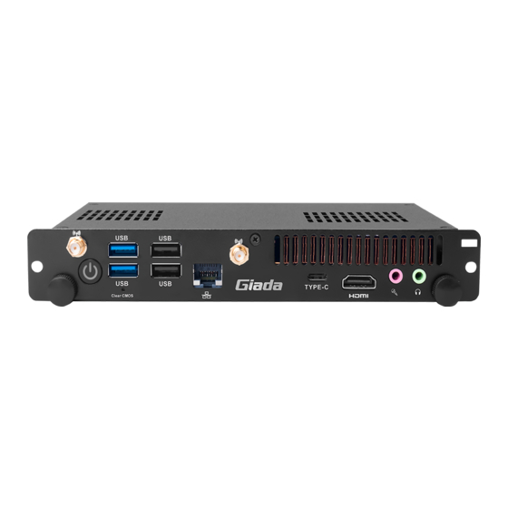
Page 5: Product Introduction
1. Product Introduction Complies with Intel OPS standards and based on Alder Lake platform, Giada PC612 is powered by Intel 12th-Gen processors and adopts dual-channel SO-DIMM DDR4-3200MHz memory (Max 32GB). The player supports max. 8K display via the 80 Pin JAE connector . It’s an ideal choice for large-format displays and modern interactive whiteboards in 24/7 use. -
Page 6: Hardware Specifications
2.2 Hardware Specifications PC612 Intel Alder Lake i3-1215U/ i5-1235U/ i7-1255U processor Processor BIOS AMI Source Code Chipset Type DDR4-3200MHz Socket SO-DIMM Memory Channel Max Capacity 32 GB Intel ® UHD Graphics (CoreTM i3 processor) ® ® Intel Iris Xe Graphics (CoreTM i5/i7 processor) DirectX12.1, OpenGL4.6, OpenCL3.0... -
Page 7: Accessories Installation Steps
Dimension 200 mm x 119 mm x 30 mm (7.87” x 4.69” x 1.18”) (W x D x H) Operating 0°C ~45°C (32°F~113°F) @0.7m/s Air Flow Temperature Environment Relative 95%@45℃ (non-condensing) Humidity Certification CE, FCC Class B 3. Accessories Installation Steps For safety reasons, please ensure that the power cord is disconnected before opening the case. -
Page 8: Memory Installation
3.1 Memory Installation This product only supports DDR4 SO-DIMM memory modules. 1. On top side, unscrew the two screws and remove the fan. Locate the SO-DIMM#1 slot on the board. On bottom side, locate the SO-DIMM#2 slot on the board. 2. -
Page 9: Wifi (M.2) Installation
3.2 WIFI (M.2) Installation 1.Plug the WIFI module into the appropriate slot. 2.Secure the module to the carrier by tightening up the screw. 3.Connect the two black cables to Main and AUX. Install antennas. - 7 -... -
Page 10: Ssd (M.2) Installation
3.3 SSD (M.2) Installation 1. Plug the SSD (M.2) into the appropriate slot. 2. Secure the module to the carrier by tightening up the screw. - 8 -... -
Page 11: Bios Setup
The descriptions relating to BIOS setup in this Manual is for reference only since the BIOS version of the product might be upgraded. Giada provides no guarantee that all the contents in this Manual are consistent with the information you acquired. - Page 12 B. Function Keys definitions Hot Key Description ↑ (Up key) Move to the previous item ↓ (Down key) Move to the next item ← (Left key) Move to the left item → (Right key) Move to the right item Exit the current interface Display the information of the current function Keys definitions.
-
Page 13: Main (Standard Cmos Setup)
Fig 1 1) Main (standard CMOS setup) This item is used for setting the date and time. 2) Advanced (advanced BIOS setup) This item is used for setting the advanced functions provided by BIOS, such as specifications of PCIe facilities,CPU, HDD, etc. 3) Security (set the administrator/user password) 4) Boot (startup configuration characteristics) 5) Save &... - Page 14 4.1 Main (Standard CMOS setting) 1) System time (hh:mm:ss) Use this item to set the time for the computer, with the format as “HH / MM / SS”. 2) System date (mm:dd:yy) Use this item to set the date for the computer, with the format as “week, MM / DD / YY”. - 12 -...
-
Page 15: Advanced (Advanced Bios Setup)
4.2 Advanced (Advanced BIOS setup) 4.2.1 ACPI Setting - 13 -... -
Page 16: Cpu Configuration
ACPI Setting Menu Description You can use the ACPI Sleep state option to control system hibernation ACPI Sleep state Suspend Disabled: Disable system Suspend. S3 (Suspend to RAM): Enable S3(Suspend to RAM) State After G3 means after restore power supply. ... - Page 17 CPU Configuration Menu Description CPU Configuration Max Battery Boot performance mode Max Non-Turbo Performance. Turbo Performance. Intel (VMX) Virtualization Intel Virtualization Technology is enabled by default. User can enable and disable Technology the Intel Virtualization Technology function. Intel (...
-
Page 18: Wake Configuration
Intel Hyper-Threading technology is enabled by default. Intel ® Hyper-Threading Technology (Intel ® HT Technology) delivers two processing threads per physical Hyper-Threading core. Highly threaded applications can get more work done in parallel, completing tasks sooner. C states The C-State function is disabled by default. ... - Page 19 Menu Description Wake Configuration Disabled: Wake Up On Lan Enabled: The Wake Up On LAN is enabled by default. Wake up By USB KB/MS Enabled/Disabled Wake Up by USB KB/Mouse from S3 Status. Enable or disable system wake on alarm event. The system will wake on the hr::min::sec specified when Select FixedTime.
-
Page 20: Trusted Computing
4.2.4 Trusted Computing - 18 -... - Page 21 TPM20 Device Found Description Firmware Version TPM FW version is 600.18 Vendor The vendor is INTC Disabled Security Device Support Enabled. This item is enabled by default. Disabled. This item is Enabled by default SHA256 PCR Bank ...
- Page 22 4.2.5 HM Monitor & Smart Fan - 20 -...
- Page 23 Menu Description Pc Hardware Monitor Status It includes "Software Mode" and "Automatic Mode". Smart Fan1 Mode Software Mode. Automatic Mode: Automatic Mode is enabled by default. FAN will stop work If temperature is lower than the Fan off Fan off temperature limit temperature limit value.
- Page 24 Menu Description The SATA controller is enabled by default. SATA Controller(s) Enabled Disabled. SATA Mode Selection Determines how SATA controller(s) operate. Control Detection of the HD-Audio device. HD Audio HAD will be unconditionally disabled when disabled. ...
- Page 25 4.3 Security If this function is selected, the following information will appear: Enter New Password hhhhhh Then enter a password which is no more than eight characters and press <Enter>. BIOS will require to enter the password again. Once you enter it again, BIOS will save the set password. Once the password item is enabled, you will be required to enter the password every time before the system entering to the setup program of BIOS.
- Page 26 4.4. Boot Menu Boot Menu Description Boot Configuration This item is use to set the wait time of entering the operation system. During the BIOS post, if user doesn't Setup Prompt Timeout press the keyboard, it won't respond unless you reboot the BIOS.
- Page 27 Boot Menu Description You can set and management legacy Hard disk device after Hard Drive BBS Priorities enabling this option. Specifies the boot Device Priority sequence from available UEFI Application Boot Priorities UEFI Application. Specifies the boot Device Priority sequence from available UEFI USB Drive BBS Priorites UEFI USB Application.
- Page 28 5. JAHC Introduction JEHE Active Hardware Control (JAHC) management system includes both hardware Micro Control Unit (MCU) and software (JAHC Technology Manager). It can support following functions: 1. Automatically boot up when power on. It is controlled by the Micro Control Unit (MCU) chip. 2.
- Page 29 b. Select Advanced- > ACPI Setting- > JAHC Enable- > Enabled. c. Press ‘F10’ to save change & exit after select “JAHC enabled” option. - 27 -...
- Page 30 Supported operation system: Windows 10 64bit, Linux 64bit. How to install JAHC software: Please download the JAHC.EXE from Giada website: www.giadatech.com, then follow up below steps: Double-click the JAHC.EXE file, the setup wizard will pop up, select destination location and click [Next] button to continue the installation.
- Page 31 b. Click [Next] button to continue the installation. Select [Create a desktop shortcut] and click [Next] button. - 29 -...
- Page 32 d. Click [Install] button to continue the installation. - 30 -...
- Page 33 Click [Finish] button to finish the installation. You can select [Launch JAHC] to run the software automatically after finishing the installation. Notice: The JAHC will be added into boot item when it is installed. It will start up when system boot up. 5.2.3 Startup &...
- Page 34 After install the JAHC software, double click the JAHC icon on taskbar and the setup menu will pop One week as a circle, maximum 3 schedules per day. Select each schedule to set up the resume time and shutdown time. Click [Confirm] button to launch the schedule. After finishing the setup, the menu window will notice the resume time and shutdown time.
- Page 35 You can click [Delay] button and set up the time to delay the shutdown or click [Cancel] button to cancel the shutdown. 5.3 Watchdog API and instruction Please contact Giada FAE (email:support@giadatech.com) for watchdog API software and instruction. - 33 -...
- Page 36 - 34 -...
Need help?
Do you have a question about the PC612 and is the answer not in the manual?
Questions and answers