Advertisement
Giada F300 Series Assembly Guide
Thank you for choosing Giada product. In such an epoch of PC development, we launched Giada
Barebone which is characterized by the mini shape, vogue and ultra-thin structure, environment
friendly, Giada will allow you to undergo new experience in the field. This Guide shows you how to
installation and uninstallation quickly and correctly.
WARNING:
This motherboard contains static-sensitive components and should be handled with care. Failure to employ
adequate anti-static measures can cause partial or complete device failure, performance degradation, or
reduced operating life. The battery must be replaced with the correct type of lithium cell battery; otherwise
there is a risk of damage to the motherboard. To avoid electrostatic discharge (ESD) damage upon handling
this product, it is strongly recommended that you wear a grounded wrist strap or other static dissipating
device.
CONTENT:
HDD, Memory, Wireless Module, 3G Module and SSD installation.
Remark:
The picture shown in this document is only a model of our series products, the actual
object is subject to change depends on the model you purchase.
HDD, Memory, Wireless Module, 3G Module and SSD installation
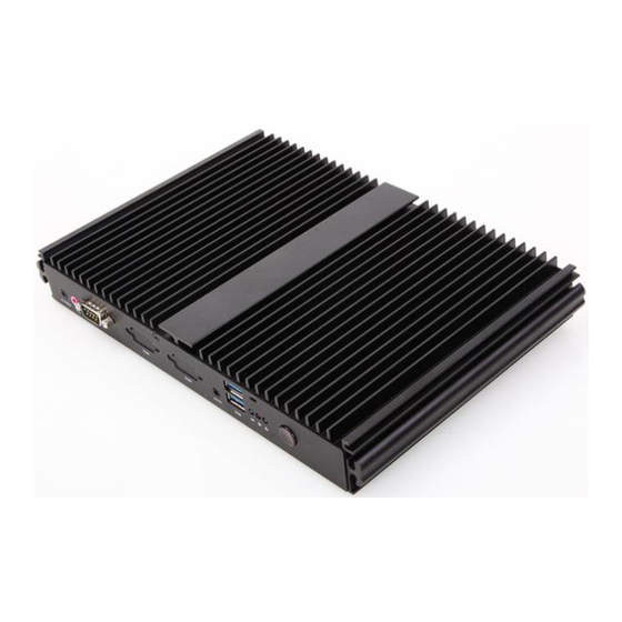
Part 1. Appearance
The Front Panel.
The Back Panel.
Advertisement
Table of Contents

Related Manuals for Giada F300 Series


Summary of Contents for Giada F300 Series
- Page 1 Thank you for choosing Giada product. In such an epoch of PC development, we launched Giada Barebone which is characterized by the mini shape, vogue and ultra-thin structure, environment friendly, Giada will allow you to undergo new experience in the field. This Guide shows you how to installation and uninstallation quickly and correctly.
- Page 2 Part 2. HDD installation Unscrew (anti-clockwise) 2 screws from top panel of the PC. Pull up half of the top panel and then turn it over avoiding the Thermal conductive strip dropping out.
- Page 3 Unscrew (anti-clockwise) 2 screws from the HDD Stand, and take off the HDD Stand. Remark: White screws are for WiFi/3G/SSD module. Two black screws are for fixing HDD. Four Circular Foot-paddings are for PC stand. Take another two black screws from the accessory bag and fix HDD to the HDD Stand (two sides).
- Page 4 Part 3. Memory, Wireless Module, 3G Module, SSD installation Unscrew (anti-clockwise) the screw from the bottom cover plate. as the picture Push the cover plate shown. Take away the cover plate and then you can see one SO-DIMM Slot for Memory, WiFi three Mini-PCI Express®...
- Page 5 Wireless Module installation Insert the module to M-PCIE slot, make sure it is locked with 1 screws. Connect Wi-Fi cable or BT cable to the Wireless Module. As the two wire is the same, there is no need to distinguish which one is the main antenna.
-
Page 6: Memory Installation
Memory installation Install the Memory module to the SO-DIMM slot as an angle about 35 degree, then press down the module to the Slot lightly until it`s locked. Cover Plate assembly Take the cover plate back and push the as the picture shown. cover plate Fix the screw back.
Need help?
Do you have a question about the F300 Series and is the answer not in the manual?
Questions and answers