Advertisement
Table of Contents
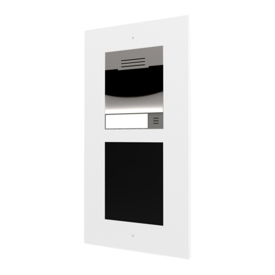
Basic Unit with or without camera
ZVP-CAM / ZVP-WOCAM
FEATURES
•
Connectors:
RJ-45 Ethernet 10/100Base-TX Auto-MDIX.
o
It allows PoE supply 802.3af – Class 0 – 12.95W.
IN1: Passive or active input (-30..30VDC).
o
0=open or VIN1>1.5VDC / 1=closed or VIN1<1.5VDC.
OUT1: Active output (8..12VDC, I
o
RELAY1: Relay contacts NO/NC 30V/1A (AC/DC).
o
External power supply input 12VDC(±15%)/2A.
o
Output LINE
o
OUT
Internal
microphone
o
connector.
•
Reset button and LED indicators (yellow, red, green).
•
Ambient conditions:
Operation: -40..60ºC y 10..95%RH (without condensation)
o
Storage: -40..70ºC y 10..95%RH
o
•
Protection index: IP54
•
1
Camera
1280x960px (angles 120ºH, 90ºV, 145ºD) and
IR light
•
Speaker 2W. Sound pressure (1 kHz, 1m): 78 dB.
•
Static or dynamic IP (DHCP compatible)
1. Basic Unit
1
5. Camera
6. Infrared LED
1
Only included in the ZVP-CAM unit.
ASSEMBLY INSTRUCTIONS
1
Depending on the installation type (surface or flush-mount),
the initial installation zone is different.
Surface installation:
© Zennio Avance y Tecnología S.L.
=400mA).
MAX
(1V
).
RMS
connector
and
GetFace
2. Board connections
1
7. Button
Flush-mount installation:
Ed. 1
1
2
3
bus
4
Board connections:
LAN
+ -
+ -
(PoE)
IN1
OUT1 RELAY1
Note:
For 12VAC/DC electromagnetic lock, it is
necessary to protect the intercom against
voltage peak while switching off the induction
load. For this way of protection, please,
connect the varistor like is showed in the next
figure near to the lock.
3. Space for additional modules
8. Blind panel
9. Allen key
2
Please remove the blind panel from the basic unit.
Further information
www.zennio.com
GetFace IP
Technical documentation
10
6
5
7
9
8
LEDs
BUS
Y
RG
LINE
+ -
RESET
MIC
OUT
12V
DC
2A
4. Internal microphone
10. Auxiliary metallic parts
Page. 1 / 2
Advertisement
Table of Contents

Related Manuals for Zennio ZVP-CAM


Summary of Contents for Zennio ZVP-CAM
- Page 1 7. Button 8. Blind panel 9. Allen key 10. Auxiliary metallic parts Only included in the ZVP-CAM unit. ASSEMBLY INSTRUCTIONS Depending on the installation type (surface or flush-mount), Please remove the blind panel from the basic unit. the initial installation zone is different.
- Page 2 Place the suitable frame (surface or flush-mounted) Fix the frame by using the supplied Allen key. Surface installation: Flush-mount installation: Surface installation: Flush-mount installation: Page. 2 / 2 © Zennio Avance y Tecnología S.L. Ed. 1 Further information www.zennio.com...
Need help?
Do you have a question about the ZVP-CAM and is the answer not in the manual?
Questions and answers