
Related Manuals for Zennio GetFace IP ZVP-WOCAM


Summary of Contents for Zennio GetFace IP ZVP-WOCAM
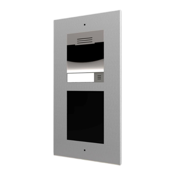
- Page 1 Zennio GetFace IP IP Video Intercom (Basic Unit) ZVP-CAM/ZVP-WOCAM User manual version: [2.26]_a Firmware version 2.26 www.zennio.com...
-
Page 2: Table Of Contents
Zennio GetFace IP CONTENTS Contents ........................... 2 Document Updates ........................3 Introduction ........................5 Installation ........................6 Device Wiring Diagram ....................6 Application Cases....................... 8 2.2.1 Single-Family Homes ..................8 Apartment Block ......................8 Configuration ........................10 GetFace IP Basic Settings ..................12 3.1.1... -
Page 3: Document Updates
Zennio GetFace IP DOCUMENT UPDATES Version Changes Page(s) Possibility of remote control via ZenCom application. Change in the recommended configuration of the system API. Test button which simulates a quick dial button press. [2.26]_a Possibility of restoring only certain configuration options when loading a backup. - Page 4 Zennio GetFace IP Clarification about “Phone Number (ID)” Automation Configuration. Accesses E-Mail Configuration. Hardware configuration of the ZVP-RFSMN module Minor text changes. Bluetooth Module Configuration. Configuration of RFID cards in Hardware section. [2.20]_a Minor corrections. Minor text changes. [2.18]_b http://www.zennio.com Tecnical Support:http://support.zennio.com...
-
Page 5: Introduction
Zennio GetFace IP 1 INTRODUCTION Zennio GetFace IP is the video intercom solution from Zennio. In combination with the supported touch panels (such as Z41 COM), it provides integration for video-call management between the entrance door of a residential environment (like single-family homes, apartment blocks or housing states with a common access) and the interior of the dwelling. -
Page 6: Installation
Zennio GetFace IP 2 INSTALLATION 2.1 DEVICE WIRING DIAGRAM Zennio GetFace IP provides several optional modules which can be connected individually to expand the number of the device functions or features. Keypad module (ZVP-KEYPAD), 5-button module (ZVP-NAME5), Touch display (ZVP-TOUCHD),... - Page 7 Zennio GetFace IP KEYPAD MODULE MODULE MODULE (optional) (optional) (optional) LEDs RESET LINE OUT1 (PoE) RELAY1 UTP CAT-5 12VDC 2A 12VAC/DC LOCK External Power supply SWITCH LOCK Max. 400 mA Figure 1 Device wiring diagram. http://www.zennio.com Tecnical Support:http://support.zennio.com...
-
Page 8: Application Cases
Figure 2 Single-family home installation. 2.3 APARTMENT BLOCK In the case of an apartment building equipped with a common Zennio GetFace IP intercom for all of them, a community network infrastructure (firewall-managed) will be required to interconnect the video intercom with each apartment. As in 2.2.1, each of aparments may or may not have its own Internet connection router. - Page 9 UTP CAT-5 Figure 3 Apartment block installation. For detailed information about the technical features of Zennio GetFace IP, as well as on security and installation procedures, please refer to the device Datasheet, bundled within the device packaging and also available at www.zennio.com.
-
Page 10: Configuration
A number of parameters will be provided for the proper, joint operation of Zennio GetFace IP and Z41 COM. During the first 30 seconds of operation (after supplying power to the video intercom), the main unit button should be pressed for 5 times. - Page 11 Zennio GetFace IP Figure 4 Configuration menu. Notes The default language of the interface is English. A Save button is provided at the bottom of each configuration page to allow saving any changes made, although a confirmation message will show up if trying to switch to another page without having saved them.
-
Page 12: Getface Ip Basic Settings
Zennio GetFace IP 3.1 GETFACE IP BASIC SETTINGS The most important fields to be configured so the video intercom can interface with Z41 COM are explained next. Those to be modified from the default configuration are, in short, the following: Phone Number (ID): identifier of the video intercom (if intending to link it to a specific box in Z41 COM). -
Page 13: Video-Call Configuration (Services)
SIP is a transmission control protocol used in IP telephony. Up to two SIP profiles can be set up. Each profile should be configured properly according to its own operation network. The following configuration settings allow Z41 COM to connect to Zennio GetFace IP. - Page 14 Zennio GetFace IP Intercom identity: configuration parameters that define the video intercom profile (see section 3.1.3.1): Display name: identification name for the video intercom, which is also shown at the start page of the web interface. Phone Number (ID): alphanumerical identifier for the video intercom. This value must match the Intercom ID parameter (in ETS) of the particular box of Z41 COM where the video intercom is desired to be linked to.
- Page 15 Zennio GetFace IP display module (ZVP-TOUCHD) or from the keypad module (ZVP-KEYPAD), if configured. The intercom’s response to an incoming call is parameterised under Incoming calls. As the video intercom is designed for one-way calls, this field is set to “Always busy” by default.
- Page 16 Zennio GetFace IP Figure 8 Audio. Transmission Quality Settings: Quality of Service DSCP Value: sets the priority of the RTP packages in the network. The value set here will be sent under the ToS (Type of Service) field of the IP package header.
- Page 17 Zennio GetFace IP VIDEO The video output settings can be configured under the Video tab. Video Codecs: It is advisable to change the H.264 video resolution for a smooth video transmission. This is possible under Services Phone Video, as shown in Figure 10.
- Page 18 Zennio GetFace IP please refer to section 3.2.3). It is also necessary to parameterise the System API the Switch API and the Camera API. To that end, the aforementioned parameters are configured as detailed below, under Services HTTP API Services.
- Page 19 Zennio GetFace IP If Z41 COM is configured with a username and a password through the Opening Method parameter, then an analogous configuration should be performed in the Accounts tab to allow the opening of the door lock system. Moreover, the Switch Access checkbox should be activated. Otherwise, the door unlocking will not work successfully.
-
Page 20: Housing Configuration & Z41 Com (Directory)
Zennio GetFace IP 3.1.3 HOUSING CONFIGURATION & Z41 COM (DIRECTORY) Homes connected to the video intercom system must be configured from Directory. The following features can be set up from this window. 3.1.3.1 USERS It is necessary to configure, at least, as many users as dwellings that may be called from the video intercom. - Page 21 Zennio GetFace IP Figure 13 Users. The Users section defines the following parameters: Name, which will identify the housing or the owner. Photo: only available if the Touch Display module (ZVP-TOUCH) is connected. E-Mail contact address (optional; see section 3.2.3.1).
-
Page 22: Switches Configuration
It is possible to configure the opening of electric locks linked to Zennio GetFace IP. This allows controlling them from Z41 COM (up to three electric lock can be enabled). For instructions on how to wire the lock system to Zennio GetFace IP please refer to section 2 and to datasheet of the device. - Page 23 Zennio GetFace IP Figure 14 Switches. Regarding the configuration, it is necessary to enable the switch in the top side box and to set the page options according to the provided lock system. Basic Settings of the switches: Switch Mode: sets the opening mode (monostable, in case it gets automatically deactivated some time after the opening order;...
- Page 24 Zennio GetFace IP Security: the output works in inverted mode but a security relay module has been installed and therefore a specific pulse sequence is necessary for the door opening (this requires the ZVP-ACSR module). Time Profile to be applied to the switch. It can be selected one of the pre- sets (see section 3.2.2.1) or a specific one.
-
Page 25: Door Configuration
Zennio GetFace IP 3.1.5 DOOR CONFIGURATION The section Hardware Door groups the configuration parameters needed to control the door opening and its access rules. DOOR This tab contains the general configuration of the door, which will be applied regardless of the access direction. - Page 26 Zennio GetFace IP ENTRY / EXIT RULES These two tabs have the same parameters but each one referring to one access direction. Figure 16 Door. Entry / Exit Rules Emergency lockdown: this button allows to block every access in that direction.
- Page 27 Zennio GetFace IP Figure 17 Door. Entry / Exit Rules. Service Cards: determine the ID of the cards used to add or delete visitor cards (which are automatically added as new users). The card reader module is required (ZVP-RFSMN). Once the ID of the Plus Card and Minus Card are added, only is needed: ...
- Page 28 Zennio GetFace IP The codes must have 2 characters minimum, but is recommended to use at least a 4-charater code. The procedure to add or delete a code is: Enter Plus Code and press the key button (ZVP-KEYPAD) or Open door (ZVP-TOUCHD).
-
Page 29: Buttons Module Call Configuration
Zennio GetFace IP 3.1.6 BUTTONS MODULE CALL CONFIGURATION The section Hardware Buttons defines the buttons and the dwelling linked to each one of them, in case a buttons module has been attached to the system (reference ZVP-NAME5). Figura 18 Buttons. -
Page 30: Tamper Switch Configuration
For that purpose, it must be connected to a KNX input or any monitoring system. That connection will remain closed after the Zennio GetFace IP frame has been installed. On the other hand, it will be open once the frame gets removed. - Page 31 Zennio GetFace IP To add a new folder, click on the button . Once the folders have been created, the users configured in the directory can be included in them by clicking on the button of the corresponding folder. Note that folders that do not contain users (at their own level or sublevels) will not be saved.
-
Page 32: Access Configuration With Rfid Card
Zennio GetFace IP SLIDESHOW The Touch Display module allows showing a screensaver or a custom slideshow after a time count. For the latter, it is possible to upload up to 8 images from the PC. Once uploaded, they can be rearranged by dragging each of them to the desired position. - Page 33 By automating the process through an RFID card reader for PC (ZVP- RFUSB). This requires installing the card reader driver, available at http://www.zennio.com, and entering the web interface of a Zennio GetFace IP with the ZVP-RFSMN module installed. By pressing on the button...
- Page 34 Zennio GetFace IP Figure 21 Access Log. The ID just obtained should be entered into the corresponding textbox. Virtual Card ID is the value to resend to Wiegand Group configured. Card activation time profiles can be configured in Directory Time Profiles (see section 3.2.2.1).
-
Page 35: Access Configuration With Bluetooth Module
Zennio GetFace IP Figure 22 NFC Card Reader Module Hardware Configuration 3.1.10 ACCESS CONFIGURATION WITH BLUETOOTH MODULE The module ZVP-BLUET provides a safe and convenient way to open doors using mobile devices with Bluetooth technology through GetFace Key application. This application is available for Android (version 4.4 or higher) and iOS (version 11.0 or... - Page 36 Zennio GetFace IP Parameter list: Auth ID: sets a unique mobile device/user identifier. It is automatically generated for pairing. It can be moved to another user or copy it to another device in the same location. Pairing state: displays the current pairing state (Inactive, Waiting for pairing, PIN validity expired or Paired).
- Page 37 Zennio GetFace IP 4. Enter the code obtained in step 2 into the input field. Figure 26 Introduction of the PIN number 5. Pairing is completed. Figure 27 Device paired The following data is transmitted to a mobile device for pairing: Location identifier (see section 3.1.10.2 for details).
- Page 38 Zennio GetFace IP User Auth ID. Once they have been paired, when the device is within the Bluetooth module range, it will appear on the application and just tapping on the button showed on Figure 28, the door will open.
- Page 39 Zennio GetFace IP As already mentioned, Bluetooth communication between GetFace IP and the GetFace Key application is encrypted. To this end, a primary key and up to three secondary keys are available, valid for a certain location. The primary key is generated automatically upon the intercom first launch and transmitted to the mobile device during pairing.
- Page 40 Zennio GetFace IP Important: in the case of loss or theft of a mobile device with access data, proceed as follows: Delete the Auth ID (see section 3.1.10.1) to prevent access. Re-generate the primary key (optionally) to avoid misuse of the encryption key stored in the mobile device.
-
Page 41: Access Configuration With Fingerprint Module
Zennio GetFace IP Operation mode: authentication method for a mobile phone: Tap in app: authentication has to be confirmed by tapping on an icon in the application running in a mobile phone. 3.1.11 ACCESS CONFIGURATION WITH FINGERPRINT MODULE The ZVP-FINGER module offers a secure and convenient way of authentication and access by reading user fingerprints. - Page 42 Zennio GetFace IP 3. Place the selected finger on the reader. This process is repeated three times for greater precision. If the reading is correct, the fingerprint appears in green. If it is wrong it appears in red and step 2 must be repeated.
-
Page 43: Magnetic Induction Loop Configuration
Zennio GetFace IP Several funtions can be selected for each fingerprint. Figure 35 Function associated with the fingerprint. Up to two fingerprints per user can be registered. On the tab Hardware Extenders will be more options for the module configuration. -
Page 44: Advanced Settings
These fields are not mandatory for a standard configuration, but they are detailed in case the end requires any of the extra features. 3.2.1 STATUS The Status window shows status information concerning Zennio GetFace IP. It consists of the following sections. 3.2.1.1 DEVICE... - Page 45 Zennio GetFace IP 3.2.1.2 SERVICES It shows basic information about the device network and the service status. Figure 37 Services. 3.2.1.3 EVENTS It shows a date-ordered register of the last events that have taken place. Figure 38 Events. http://www.zennio.com Tecnical...
-
Page 46: Directory
Zennio GetFace IP 3.2.2 DIRECTORY Homes connected to the video intercom system are configured in Directory. The following advanced features can be set up from this window: 3.2.2.1 TIME PROFILES Time profiles allow restricting the use of the RFID cards and the numeric codes. In particular, it is possible to define time bands for: Locking all incoming calls for a specific user. -
Page 47: Services
The Services section provides the following advanced settings: 3.2.3.1 E-MAIL Zennio GetFace IP users can be notified of all missed or successful calls via e-mail, provided that an Internet connection is available (e-mails about accesses can also be sent when using the module ZVP-RFSMN). Also, if the video intercom is camera- equipped, one or more snapshots taken during the call or the ringing can be attached. - Page 48 Zennio GetFace IP The video intercom sends e-mails to each user for whom a valid e-mail address has been included in the user list. If the E-Mail field is blank in the user list, e-mails are sent to the default address.
- Page 49 Zennio GetFace IP E-Mail Sending Diagnostics: allows testing the e-mail sending functionality and the current configuration by sending a test e-mail to a defined address. Please enter an e-mail address and click on the Apply and Test button. The current sending status is then shown to allow the detection of issues.
- Page 50 Zennio GetFace IP The e-mail body can contain HTML tags as well as special symbols to represent the username, date, time, video intercom ID or called number, which will be replaced by the actual values before sending. $User$: user name.
- Page 51 Zennio GetFace IP SIP Registration Lost. Device Rebooted. Tamper Switch Activated. SIP Registration Lost Message: sets the e-mail subject and the e-mail body to be sent in the event of SIP registration lost. HTML format symbols can be used to edit e-mail body.
- Page 52 3.2.3.3 WEB SERVER Figure 45 Web Server. The login username and password of the Zennio GetFace IP web interface (by default, admin and zennio respectively) can be modified from this section. The language of the interface can be customised too.
-
Page 53: Hardware
Zennio GetFace IP 3.2.4 HARDWARE The following items can be configured in the Hardware section: 3.2.4.1 AUDIO Figure 46 Audio. Master Volume: audio volume level for both calls and signals (ringtones). Adaptive Volume: if enabled, a Maximum Gain and a Sensitivity Threshold can be parameterised. - Page 54 The default video source is set in this tab: either an internal camera (the on-board camera of Zennio GetFace IP) or an external IP camera can be configured. Once the default video source is selected and the configuration has been set, a live preview can be performed.
- Page 55 IR LED Brightness Level: defines the brightness level of the infrared LED in the range 0-100% with steps of 25%. If set to automatic, the infrared light will be activated by Zennio GetFace IP in case the ambient light is low and the camera is being used.
- Page 56 Figure 50 Digital inputs. Secured State Control: defines which of the inputs will be used for the secured state detection, which is indicated by Zennio GetFace IP through a LED. This parameter can be applied to pushbuttons for door opening. Input Mode allows setting whether this input is inverted or not.
-
Page 57: System
Parameters related to the device network interfaces are set in this section. BASIC Zennio GetFace IP works by default with a static IP. However, it is possible to configure it to work with a DHCP server. Being the DHCP option deactivated, it is possible to configure the following options: Manual Settings: allows setting a static IP address, the network mask and the default gateway. - Page 58 It is possible to synchronise the date and time according to those from the PC (browser). Once synchronised, the Time Zone must be set, so winter/summer time shifts are performed according to the Zennio GetFace IP time zone. It is also possible to define the time zone rules manually through the Time Zone Rule parameter.
- Page 59 Zennio GetFace IP Figure 52 Date and Time. 3.2.5.3 AUTO PROVISIONING It is recommended to deactivate the automatic firmware update as well as the automatic configuration update. It is advisable to perform these updates manually to do so in a controlled way and to make a backup before the update, so that settings are saved and does not affect the normal operation of the unit (see section 3.2.5.4 for...
- Page 60 Zennio GetFace IP 3.2.5.4 MAINTENANCE This section allows performing general maintenance operations. It also provides general information about it. Figure 54 Maintenance. The main actions than can be carried out are: Restore Configuration: uploading a configuration backup file to the device.
- Page 61 Before upgrading the firmware, it is recommended to make a backup copy of the current configuration ("Back Up Configuration"). Please consult Zennio before updating the firmware to a different version than the one indicated on the cover of this manual.
- Page 62 Join and send us your inquiries about Zennio devices: http://support.zennio.com Zennio Avance y Tecnología S.L. C/ Río Jarama, 132. Nave P-8.11 45007 Toledo. Spain. Tel. +34 925 232 002. www.zennio.com info@zennio.com...
Need help?
Do you have a question about the GetFace IP ZVP-WOCAM and is the answer not in the manual?
Questions and answers