Table of Contents
Advertisement
Quick Links
Advertisement
Table of Contents

Related Manuals for Qcells Q.PEAK DUO BLK-G10+ / HL Series


Summary of Contents for Qcells Q.PEAK DUO BLK-G10+ / HL Series
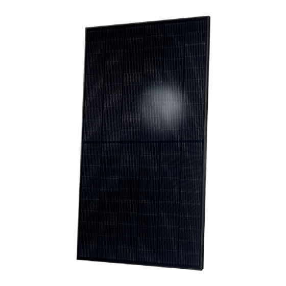
- Page 1 Installation and operation manual Q.PEAK DUO BLK-G10+ / HL solar module series...
-
Page 2: Table Of Contents
■ Other applicable documents (such as country-specific ■ Additional information can be found on our website at regulations for pressure equipment, operational safety, www.qcells.com. 4 Electrical Connection hazardous goods, and environmental protection). Regulations and requirements specific to the system. ■ Intended use 4.1 Safety... -
Page 3: Introduction
1 Introduction 2 Planning 2.1 Technical specifications Validity For additional information see the relevant datasheet of the module provided at www.qcells.com. These instructions are only valid for crystalline solar modules PRODUCT LINE Q.PEAK DUO BLK-G10+ / HL from the company Q CELLS as specified at chapter „2.1 Technical Specifications“. -
Page 4: Mounting Options
2 Planning 2 Planning 2.2 Requirements 2.3 Mounting options Installation Site Ensure that no additional forces are applied through the Fig. 2: Installation options for crystalline Q CELLS modules. All dimensions are given in inch (mm in brackets). Also observe the North 0.79 - 25.6 America mounting system into the module except for the wind and snow maximum test loads and clamping range as specified on the following page. - Page 5 2 Planning 2 Planning 2.3 Mounting Options 2.3 Mounting Options TYPE OF MOIUNTING POINT MOUNTING SYSTEM LINEAR MOUNTING SYSTEM REQUIREMENTS INSTALLATION OPTIONS Installation NOT PERMITTED The loads in the table are related to the mechanical stability of the solar modules. The mechanical with insertion profiles stability of the mounting system including clamps has to be evaluated by the system supplier.
-
Page 6: Electrical Layout
Modules may be damaged by the occurrence of reverse currents accident-prevention and safety regulations. Do not install damaged modules. sheet referring to the relevant Module (available at www.qcells. (caused by module defects, ground leaks, or defective insulation). While working wear clean gloves. -
Page 7: Preparation Of Installation
3 Installation 3 Installation 3.1 Safety and Transport 3.2 Preparation of installation Note! Module damage may occur! Note! Module damage may occur! Danger! Risk of fatal injury due to electric shock! Warning! Risk of injury due to falling modules! Never lift or move the module with the connection Never step on modules. -
Page 8: Module Installation
3 Installation 4 Electrical Connection 3.3 Module installation 4.1 Safety Danger! Option 1: Maintain an interval of at least 10 mm between two Danger! Risk of fatal injury due to electric shock! Risk of fatal injury due to electric shock! modules along the short side and 5 mm along the Fasten the module with 4 clamps in the specified Never open the junction box. -
Page 9: Electrical Installation Safety
4 Electrical Connection 4 Electrical Connection 4.2 Electrical installation safety 4.3 Connection of modules Danger! Risk of fatal injury due to electric shock! Danger! Risk of fatal injury due to electric shock! Use solar cables for the connection at the junction Note! Module damage may occur! box outlet. -
Page 10: After Installation
4 Electrical connection 5 Grounding 4.4 After installation Protective Grounding The grounding lug should be attached to the frame grounding Ensure that all necessary safety and functional tests Note! Module damage may occur! hole using a stainless steel screw, toothed lock washer or KEPS In order to prevent electrical shock or fire, the frame of the have been carried out according to applicable nut (in order to penetrate the anodized layer) and backing nut. -
Page 11: Faults And Defects
6 Faults and defects 8 Maintenance and 8 Maintenance and Cleaning Cleaning DANGER! Q CELLS solar modules are known for a long operating life and NOTE! Free the substructure from any dirt and debris (leaves, minimal maintenance effort and expense. Dirt and grime are Risk of fatal injury due to electric shock! Dust and dirt are abrasive materials! bird nests, etc.). - Page 12 HANWHA Q CELLS AMERICA INC. EMAIL inquiry@us.q-cells.com +1 949 748 59 69 400 Spectrum Center Drive Suite 1400 Irvine, CA 92618 USA www.qcells.com Subject to change without notice. © Qcells Installation manual solar modules Q.PEAK DUO BLK-G10+_HL_modules_series_2022-05_Rev01_NA...
Need help?
Do you have a question about the Q.PEAK DUO BLK-G10+ / HL Series and is the answer not in the manual?
Questions and answers