Table of Contents
Advertisement
Quick Links
USER MANUAL
MODEL
SYSTEM
INVERTER
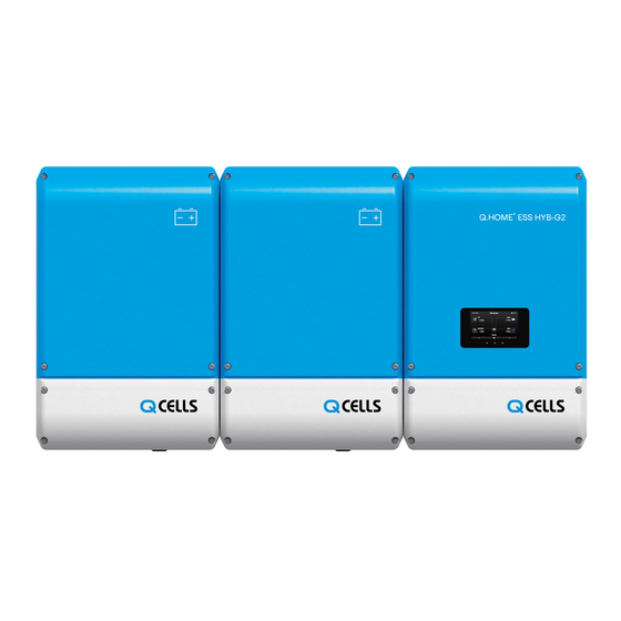
Q.VOLT G2 HYB-4.6kW.1.1
BATTERY
NOTICE
•
Do not operate with other components not approved by the ESS systems.
(Connecting other products in parallel to Q.HOME+ ESS HYB G2 may result in abnormal operation.)
•
The internet connection is required to use all functions of the ESS system.
•
If you have a problem, please contact the installer.
•
The Specifications of the product may be modified without prior notice to improve product quality.
GERMANY
Q.HOME+ ESS HYB G2
Q.SAVE G2 4kWh B1.1.1
AUSTRALIA
Q.HOME+ ESS HYB G2
Q.VOLT G2 HYB-5kW.1.1
Q.SAVE G2 4kWh B1.1.1
Eng 05/19
Advertisement
Table of Contents

Related Manuals for Qcells Q.HOME+ ESS HYB G2


Summary of Contents for Qcells Q.HOME+ ESS HYB G2
- Page 1 • Do not operate with other components not approved by the ESS systems. (Connecting other products in parallel to Q.HOME+ ESS HYB G2 may result in abnormal operation.) • The internet connection is required to use all functions of the ESS system.
-
Page 3: Table Of Contents
TABLE OF CONTENTS Table of Contents - - - - - - - - - - - - - - - - - - - - - - - - - - - - - - - - - - - - - - - - - - - - - - - - - - - - - - - - - - - - - - - - - - - - - - - - - Table of Tables - - - -- - - - - - - - - - - - - - - - - - - - - - - - - - - - - - - - - - - - - - - - - - - - - - - - - - - - - - - - - - - - - - - - - - - - - - - - Table of Figures... - Page 4 Homepage - - - - - - - - - - - - - - - - - - - - - - - - - - - - - - - - - - - - - - - - - - - - - - - - - - - - - - - - - - - - - - - - - - - - - - - - - 5.3.1 Service Terms - - - - - - - - - - - - - - - - - - - - - - - - - - - - - - - - - - - - - - - - - - - - - - - - - - - - - - - - - - - - - - - - - - - - - -...
- Page 5 TABLE OF TABLES [ Table 1-1 : Symbol Description 1 ] - - - - - - - - - - - - - - - - - - - - - - - - - - - - - - - - - - - - - - - - - - - - - - - - - - - - - - - - - - - - [ Table 1-2 : Symbol Description 2 ] - - - - - - - - - - - - - - - - - - - - - - - - - - - - - - - - - - - - - - - - - - - - - - - - - - - - - - - - - - - - [ Table 1-3 : Symbol Description (Battery) ]...
- Page 6 TABLE OF FIGURES [ Figure 2-1 : MEN Link ] - - - - - - -- - - - - - - - - - - - - - - - - - - - - - -- - - - - - - - - - - - - - - - - - - - - - -- - - - - - - - - - - - - - - - - - - - [ Figure 2-2 : TN-S Network System Connection Diagram ] - - -- - - - - - - -- - - -- - - - - - - -- - - - - - - - - - - - - - - - - - - - [ Figure 2-3 : TT Network System Connection Diagram ]...
- Page 7 This page is intentionally left blank.
-
Page 8: Information In This Manual
1. Information in this Manual 1.1 About this Manual This is the user’s manual for the Q.HOME+ ESS HYB G2. This user manual is specially designed to detail the device’s functions and features. Please read this manual before using the device to ensure safe and proper use. -
Page 9: [ Table 1-1 : Symbol Description 1 ]
Symbols Description Beware dangerous voltage. The ESS operates at high voltage. All works related to the ESS can only be performed by an electrical technician. Beware of hot surface. The INVERTER can become hot during operation. Avoid contact during operation. Follow the guidelines in all relevant documents enclosed along with the INVERTER. -
Page 10: [ Table 1-2 : Symbol Description 2 ]
Symbols Description Symbols Description Out position of a bi-stable Input terminal or rating push control Output terminal or rating Bidirectional terminal rating Caution : Risk of Electric Shock and Energy Storage Timed Discharge Caution : Risk of Hearing Damage and Wear Hearing Protection Wear hearing protection [ Table 1-2 : Symbol Description 2 ] Symbols... -
Page 11: Safety
• The Q.HOME+ ESS HYB G2 is intended for residential use only. • The Q.HOME+ ESS HYB G2 should not be used for commercial or building. The Q.HOME+ ESS HYB G2 is designed for residential use. It is a single-phase, Grid-connected system of solar energy sources and Li-Ion Battery energy storage. -
Page 12: Network System Connection Diagram
2.1.2 Network System Connection Diagram [ Figure 2-2 : TN-S Network System Connection Diagram ] [ Figure 2-3 : TT Network System Connection Diagram ] Safety... -
Page 13: Identifying The Product
■ Device-specific characteristics ■ Certification Lists ■ Warnings and Notification Q.HOME+ ESS HYB G2 ■ Q.HOME+ ESS HYB G2 • Q CELLS’s ESS For Home with Hybrid Inverter G2 INVERTER ■ G2 for Germany : Q.VOLT G2 HYB-4.6kW.1.1, HSHP-4601-1 • HYB-4.6kW.1.1 : Hybrid Inverter rated power 4.6kW single phase ver.1 ■... - Page 14 The Type Label is shown in the [Figure 2-4], [Figure 2-5], [Figure 2-6] and [Figure 2-7]. [ Figure 2-4 : INVERTER Name Plate [ Figure 2-5 : INVERTER Name Plate (Germany) ] (Australia & New Zealand) ] Model Name : HSHP-4601-1, Q.VOLT G2 HYB-4.6kW.1.1 (The specifications are the same.) Safety...
-
Page 15: Figure 2-6 : Battery Name Plate ]
[ Figure 2-7 : DRM Name Plate ] [ Figure 2-6 : Battery Name Plate ] Model Name : HSBE-4001, Q.SAVE G2 4kWh B1.1.1 (The specifications are the same.) Safety... -
Page 16: Installation Application Suitable For Safety
PV panel capacity, and the maximum input voltage of the PV String must be limited to 550V or less. As shown in the [Figure 2-8], the Q.HOME+ ESS HYB G2 uses the two independent channels of the PV Input ({PV1+, PV1-}, {PV2+, PV2-}). They are used independently for running the maximum power from the sources of PV1 and PV2. -
Page 17: Technical Specifications
2.1.5 Technical Specifications Germany PV Data (DC) Max. input total power 6.6 kWp Max. input power per string 3.3 kWp 550 V Max. input voltage Min. input voltage / Initial input voltage 125 V / 150 V per string MPPT voltage range 125 V~500 V Max. -
Page 18: [ Table 2-1 : Technical Specifications (Germany) ]
Grid Input Rated / Maximum input apparent power 3000 / 4000 VA Rated / Maximum input active power 3000 / 4600 W Rated input voltage 230 Va.c. Rated / Maximum continuous input current 13/25 Aa.c. Rated input frequency 50 Hz Max. - Page 19 Australia & New Zealand PV Data (DC) Max. input total power 6.6 kWp Max. input power per string 3.3 kWp Max. input voltage 550 V Min. input voltage / Initial input voltage 125 V / 150 V per string MPPT voltage range 125 V~500 V Max.
-
Page 20: [ Table 2-2 : Technical Specifications (Australia & New Zealand) ]
Grid Input Rated / Maximum input apparent power 3000 / 4000 VA Rated / Maximum input active power 3000 / 4600 W Rated input voltage 230 Va.c. Rated / Maximum continuous input current 13/25 Aa.c. Rated input frequency 50 Hz Max. -
Page 21: [ Table 2-3 : Maximum Charge Current Limit ]
Australia & New Zealand Germany Ambient temperature (°C) [ Figure 2-9 : Derating Curve ] Max Charge Current T<0°C 0°C ≤ T < 10°C 10°C ≤ T < 25°C 25°C ≤ T < 40°C 40°C ≤ T < 50°C T ≥ 50°C Cell Body Temperature (°C) [ Figure 2-10 : Battery Charge Limit ] Item... -
Page 22: [ Table 2-4 : Maximum Discharge Current Limit ]
Max Disharge Current 19.6 10.5 10.5 T<-20°C -20°C ≤ T < -10°C -10°C ≤ T < 0°C 0°C ≤ T < 40°C 40°C ≤ T < 50°C T ≥ 50°C Cell Body Temperature (°C) [ Figure 2-11 : Battery Discharge Limit ] Item Specification Remarks... -
Page 23: Safety Guidelines
(+) and negative (-) terminals with metallic object. All work on the ESS and electrical connections must be carried out by qualified personnel only. The ESS within Q.HOME+ ESS HYB G2 provides a safe source of electrical energy when operated as intended and as designed. -
Page 24: Symbol Indication
2. Please contact your installer or Q CELLS if a significant event message is shown on the LCD screen or if the Q.HOME+ ESS HYB G2 reports an event. Refer to the table of event messages for different significant/general events. -
Page 25: Product Overview
3. Product Overview The Q.HOME+ ESS HYB G2 includes the PV INVERTER, Battery charger/discharger, Li-Ion Battery, and EMS. The basic operating modes consist of Stand-Alone (Back up) mode, PV generation mode, PV generation + charge/discharge mode. The operation mode of this product is automatically determined by the EMS algorithm. -
Page 26: Battery Product Overview
3.2 Battery Product Overview ① ⑥ ② ③ ④ ⑤ ⑦ [ Figure 3-2 : Part View of Battery Pack ] Description Description ① Battery (Made by Samsung SDI) ④ Cable Gland ② BMS Board ⑤ BMS Communication Connector ③ Terminal and Circuit Breaker ⑥,⑦... -
Page 27: Operating Modes
4. Operating Modes This system is composed of six modes : PV Auto, PV Only, Battery discharge, Standby, Maintenance (forced charge), and Stand-Alone (Back-up). The event check status should not be considered as any specific mode. 4.1 Standby Mode This is the standby mode before converting to operation mode (PV Auto, PV Only, Battery discharge mode). -
Page 28: Strong
4.3.2 Strong Solar energy generation and Battery charging are available. The solar-generated power is charged to the Battery based on the EMS decision. • Use smart meter. The energy supply priority is : load (sub+main) > battery > grid • Not use smart meter. The energy supply priority is : sub_load > battery > grid Battery Grid Output Power... -
Page 29: Pv-Only Mode
4.4 PV-Only Mode This mode enables the solar energy to be generated. However, the Battery charge-discharge does not operate. A maximum of power or less of solar energy generation power can be sent to Grid based on the EMS decision. •... -
Page 30: Stand-Alone (Back Up) Mode
4.6 Stand-Alone (Back-up) Mode When Q.HOME+ ESS HYB G2 is disconnected from the grid, Q.HOME+ ESS HYB G2 enters into the Stand-Alone (Back-up) Mode. • Use smart meter. The energy supply priority is : sub_load > battery • Not use smart meter. The energy supply priority is : sub_load > battery... -
Page 31: Communication
5. Communication 5.1 Overview When the Internet connection is properly completed, you can monitor the system operation status on the computer. 5.2 A connecting method of DRM connection The INVERTER supports the DRM (Demand Response Mode) function as specified in AS 4777.2 2015. -
Page 32: Figure 5-1 : Drm Connection Method ]
External Connector RJ45 LAN Cable [ Figure 5-1 : DRM Connection Method ] Step 1 ) Enter SIM (Installer) Page. * Enter http://Your_IP:8000 or http://17.91.23.196:8000 (Static IP) Step 2 ) Click Operating Test button. Step 3 ) Click DRM-HW button. * Make sure that the color of button changes to yellow. -
Page 33: Homepage
5.3 Homepage Any customer who has purchased this device can use a web browser (https://myess.hansoltechnics.com) or a smart phone to check its current operation status and receive various statistical information on operation in the house or remotely. 5.3.1 Service Terms This service is provided only when the device is connected to the Internet, and specific services may require additional information only after approval from the customer. -
Page 34: Password Initialization
5.3.5 Password Initialization A customer who forgets the password during use can initialize the password by using the password initialization menu on the homepage. On the log-in page, select the “Forgot your id or password?” menu, and when the customer confirms the ID and the e-mail address created during membership registration, the initialized password is sent to the registered e-mail address. -
Page 35: Figure 5-5 : Backup Mode Monitoring Page ]
The [Figure 5-5] shows the backup mode screen. This mode can be specified by the user. Since the grid does not consume power separately in the backup mode, it shows only the ESS. In the figure below, warning on ESS is an error that power does not come on the Grid. [ Figure 5-5 : Backup Mode Monitoring Page ] 5.3.6.2 Consumption Report The household power consumption information collected during energy meter linkage... -
Page 36: Mobile Service
[ Figure 5-7 : Forecast Page ] 5.3.6.5 Notices You can check the notice message whenever there is an update or any other change in the service. 5.3.6.6 Software Versions You can check the software version of the product on the monitoring page. Software Version [ Figure 5-8 : Setting Page ]... -
Page 37: Maintenance For Problem Solving
6. Maintenance for Problem Solving CAUTION Do not disassemble the parts in operation for cleaning purposes. High voltage can cause lethal damage to the human body. 1. Please make sure that the AC and DC switch relay in the distribution box is disconnected. -
Page 38: Input / Output Terminal Check
6.2.2 Input / Output Terminal Check • Check the input / output terminal when the device fails to work with significant errors. • Check the input / output terminal after turning off the AC circuit breaker and DC disconnect switch. •... -
Page 39: Checking Battery Problem
The Li-Ion Battery module can be replaced if it fails to work properly. The Q.HOME+ ESS HYB G2 uses a Battery pack manufactured by SAMSUNG SDI. When you have to replace the Battery module, please contact Q CELLS and provide the item's name and the serial number of the Q.HOME+ ESS HYB G2. -
Page 40: Message Description
7. Message Description 7.1 LED Indications As shown in the [Figure 7-1], the LED of Q.HOME+ ESS HYB G2 is located at bottom of LCD. The color of LED depend on current status of INVERTER and LED display information can be checked in [Table 7-1]. -
Page 41: Starting The System
7.2 Starting the System After completing the installation, turn on the AC circuit breaker installed in the distribution box and then turn on the DC disconnect switch on the product. Check the system check message on the front LCD screen. 7.2.1 Loading Screen &... -
Page 42: Home Screen Configuration Information
7.3 Home Screen Configuration Information ② ③ ④ ① Hybrid ESS 02 : 52 PM LOAD 5.06kw 1.47kw ⑧ ⑨ BATTERY GRID ⑬ 1.60kw ⑪ 1.98kw ⑩ Normal ⑫ ⑥ ⑤ ⑦ [ Figure 7-4 : Standby State Indication Screen before the EMS Command ] Screen Information Description Time Information... -
Page 43: Home Menu Structure
7.4 Home Menu Structure If you touch next or previous button, the screen is displayed as shown in the [Figure 7-4]. The description of each screen refer to Chapter 7.6. [ Figure 7-5 : Home Menu Structure ] Message Description... -
Page 44: Status Description
7.5 Status Description Mode Display Description The electrical power is generated Generation by PV. Battery The Battery is charging. Charge Battery The Battery is discharging. Discharge Supply the electrical power of Grid Input Grid to INVERTER. The power generated from the Grid Output PV is fed into the Grid. -
Page 45: Operation Sequence
7.6 Operation Sequence Battery Grid Load Auto W/S Mode PV Output Grid Charge Battery Discharge Stand Alone O : It enters when there is a battery fault. X : Don’t care. One of the PV and the battery is in a steady state. [ Table 7-4 : ELA Mode ] ELA Mode Auto w/s... -
Page 46: Information Display
7.7 Information Display 7.7.1 PV Information Display [ Figure 7-6 : PV Information Display ] Display Description PV1 Voltage Display current PV1 voltage PV1 Current Display current PV1 current PV1 Power Display current PV1 power PV2 Voltage Display current PV2 voltage PV2 Current Display current PV2 current PV2 Power... -
Page 47: Grid Information Display
7.7.2 Grid Information Display [ Figure 7-7 : Grid Information Display] Display Description Voltage Display Grid voltage Frequency Display Grid frequency Current Display Grid current Power Display Grid active power Power Factor Display Grid power factor Today Feed-in Power Display today’s power received from the Grid Today Feed-out Power Display today’s electricity sent to the Grid Total Feed-in Power... -
Page 48: Load Information Display
7.7.3 Load Information Display [ Figure 7-8 : Load Information Display ] Display Description Voltage Display Load voltage Current Display Load current Frequency Display Load frequency Power Display Load active power Today Power Display today’s Load power Total in Power Display the amount of power used in today's Load Graph Display Load power graph (Daily/Weekly/Monthly/Yearly) -
Page 49: Battery Information Display
7.7.4 Battery Information Display [ Figure 7-9 : Battery Information Display ] Display Description Voltage Display Battery voltage Current Display Battery current Power Display Battery charging / discharging power State of charge State of health Today Charge Power Display today's Battery charge power Today Discharge Power Display Battery power factor Total Power Charge... -
Page 50: System Information Display
7.7.5 System Information Display [ Figure 7-10 : System Information Display ] Display Description Product Model Name of this product Product Country Country using this product IP Address IP Address Software Version Software version of this product PMS Version Software version of PMS PCS Master Version Software version of PCS master PCS Slave Version... -
Page 51: Error Information Display
7.7.6 Error Information Display [ Figure 7-11 : Error Information Display ] Display Description Date The date the fault occurred. Time The time the fault occurred.ed. Error Type of fault (See Chapter 7.7) If there are more than 10 errors, the first error is cleared. [ Table 7-10 : Error Information Display Description ] Message Description... -
Page 52: General Events
7.8 General Events The general events contain warnings and protection. The warning level events does not stop the generating process. A displayed warning message automatically disappears as soon as the issue is resolved. When protection level events occur, the product stop the generating process. The process may automatically resume as long as the issue is resolved. - Page 53 WEB Display HMI Display Description Measures D06P BDC1 DOCP P BDC1 Discharge Over The product stops the generating process Current Peak Protection because a significant protection event has occurred. Wait until the event message disappears. After the event message is removed, it automatically returns to normal.
- Page 54 WEB Display HMI Display Description Measures D23P BDC OVP P BDC Over Voltage The product stops the generating process Peak Protection because a significant protection event has occurred. Wait until the event message disappears. After the event message is removed, it automatically returns to normal. If it is not removed until the time limit is reached, it is converted to a significant event.
- Page 55 WEB Display HMI Display Description Measures G04P INV OC P INV RMS Over Current The product stops the generating process Protection because a significant protection event has occurred. Wait until the event message disappears. After the event message is removed, it automatically returns to normal. If it is not removed until the time limit is reached, it is converted to a significant event.
- Page 56 WEB Display HMI Display Description Measures G14P GRID OVP P Grid Over Voltage The product stops the generating process Peak Protection because a significant protection event has occurred. Wait until the event message disappears. After the event message is removed, it automatically returns to normal. If it is not removed until the time limit is reached, it is converted to a significant event.
- Page 57 If the electric power system blacks out, ISLANDING P Protection it automatically detects the state and turns off the Q.HOME+ ESS HYB G2. (shifting the frequency of the inverter away from nominal conditions in the absence of a reference frequency. (frequency shift))
- Page 58 WEB Display HMI Display Description Measures L05P Load OVP P Load Over Voltage The product stops the generating process Peak Protection because a significant protection event has occurred. Wait until the event message disappears. After the event message is removed, it automatically returns to normal. If it is not removed until the time limit is reached, it is converted to a significant event.
- Page 59 WEB Display HMI Display Description Measures S06P PV1 OC P PV1 RMS Over The product stops the generating process Current Protection because a significant protection event has occurred. Wait until the event message disappears. After the event message is removed, it automatically returns to normal. If it is not removed until the time limit is reached, it is converted to a significant event.
- Page 60 WEB Display HMI Display Description Measures S17P PV2 OCP P PV2 Over Current The product stops the generating process Peak Protection because a significant protection event has occurred. Wait until the event message disappears. After the event message is removed, it automatically returns to normal. If it is not removed until the time limit is reached, it is converted to a significant event.
- Page 61 WEB Display HMI Display Description Measures S33P DCLINK OV P DCLINK RMS Over The product stops the generating process Voltage Protection because a significant protection event has occurred. Wait until the event message disappears. After the event message is removed, it automatically returns to normal. If it is not removed until the time limit is reached, it is converted to a significant event.
-
Page 62: Battery General Events (Protection)
7.8.2 Battery General Events (Protection) Type : PROTECTION WEB Display HMI Display Description Measures B01P BAT1 CHG BAT1 Charge Over The product stops the generating process OC P Current Protection because a significant protection event has occurred. Wait until the event message disappears. - Page 63 WEB Display HMI Display Description Measures B07P BAT1 COM P BAT1 Communication Power reset of the system is required. Protection If the symptom persists after reset, replace the cable connecting the Battery pack and the INVERTER. After replacement, repair of BMS or PCS Control Board is necessary. B08P BAT1 ADD P BAT1 Additional...
- Page 64 WEB Display HMI Display Description Measures B16P BAT2 CEL BAT2 Cell Over When the maximum cell temperature is OT P Temp Protection above protection level, thus terminating the system. Automatically returns to normal when the maximum cell temperature goes below the limit value.
- Page 65 WEB Display HMI Display Description Measures B26P BAT3 CEL BAT3 Cell Over When the maximum cell temperature is OT P Temp Protection above protection level, thus terminating the system. Automatically returns to normal when the maximum cell temperature goes below the limit value.
- Page 66 WEB Display HMI Display Description Measures B36P BAT4 CEL BAT4 Cell Over When the maximum cell temperature is above OT P Temp Protection protection level, thus terminating the system. Automatically returns to normal when the maximum cell temperature goes below the limit value.
-
Page 67: System General Events (Protection)
WEB Display HMI Display Description Measures B46P BAT5 CEL BAT5 Cell Over Temp When the maximum cell temperature is OT P Protection above protection level, thus terminating the system. Automatically returns to normal when the maximum cell temperature goes below the limit value. -
Page 68: [ Table 7-13 : System General Events Protection List ]
7.7.3 System General Events (Protection) Type : PROTECTION WEB Display HMI Display Description Measures P01P Unknown Unregistered Failure It is an unregistered fault. Turn off and restart the system. Please contact the Q CELLS Service –Hotline, if an error occurs continuously. -
Page 69: Arrangement Of Terms
8. Arrangement of Terms Chapter 1 Q.HOME Residential Energy Storage Chapter 2 Li-Ion Battery Li-Ion Battery Photo Voltaic Distribution Box A box containing AC, DC ON-OFF switches for electricity distribution Alternating Current Direct Current Liquid Crystal Display INVERTER An electric circuit that converts DC to AC and vice versa Converter An electric circuit that converts DC to DC PV String... -
Page 70: Contact
9. Contact Hanwha Q CELLS Corporation ■ : Q CELLS 86 Cheonggyecheon-ro Jung-gu Seoul Korea 04541(+82(0)2-729-3163) E-Service, Germany ■ : E-Service Haberkorn GmbH Augustenhöhe 7 06493 Harzgerode (Technical Support, +49(0)39484-9763-85, q.home@e-service48.com) Hanwha Q CELLS Australia Pty Ltd ■ : Suite 1, Level 1, 15 Blue Street North Sydney, NSW 2060 Australia (+61 (0)2 9016 3033, qhome.au@q-cells.com) For technical problems or inquiries for use, please contact the installation company. - Page 72 Manufactuere & Warranty Provider : Hanwha Q CELLS & Advanced Materials Corporation 86 Cheonggyecheon-ro, Jung-gu, Seoul korea 04541 Eng 05/19...
Need help?
Do you have a question about the Q.HOME+ ESS HYB G2 and is the answer not in the manual?
Questions and answers