
Related Manuals for Caravaggi Bio 80


Summary of Contents for Caravaggi Bio 80
- Page 1 USE AND MAINTENANCE INSTRUCTION MANUAL Bio 80 BEFORE USING THE MACHINE, READ THE INSTRUCTION MANUAL...
- Page 2 1. HOW TO USE AND KEEP THE INSTRUCTION MANUAL This instruction manual is aimed at the user of the machine , the owner , the maintenance cleaning operator and the repair technician and must always be avaiable for consultation . The instruction manual shows the user for which the machine was designed and the machine’s technical characteristics .
-
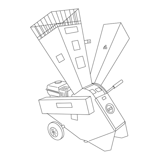
Page 3: Identification Of Main Parts
2. IDENTIFICATION OF MAIN PARTS 1. Hopper with guards 2. Chaff cutter hopper 3. Petrol engine-electric motor 4. Wheels / axle 5. Chassis 6. Sieve lever 7. Power take-off for MTC 8. Machine support... -
Page 4: Correct Use Of The Machine
The operator must be aware of all the instructions given in the instruction manual . 4. UNPACKING AND PREPARATION The Bio 80 bio-shredder is delivered partially dismantled. It ca be arranged on pallets to facilitate handling and transport before installation, depending on the versions. - Page 5 Fig. 4 Remove all the bio-shredder components from the packing. Remove the snap catches from the axle and position the axle in its seat in line with the central pin. Mount the castors and the stop washers. ...
-
Page 6: Technical Characteristics
5. TECHNICAL CHARACTERISTICS The EC identification plate is clearly visible on the Bio 80 bio- chopper ( fig. 5 ) . In all communications with the manufacturer state the serial number on the identification plate . MACCHINE INDUSTRIALI 25037 PONTOGLIO (BS) - VIA M. ADAMELLO, 20 TELEF. -
Page 7: Safety Norms
6. SAFETY NORMS Training The machine must not be used by under 16’s and persons who have not learnt the user instructions . The operator is responsible for third parties present in the work area . Keep children and domestic animals at distance when the bio-chopper is in operation . - Page 8 If the blades undergo heavy shock and function in an anomalous manner , stop the engine , remove the spark plug hood and request expert advice . Caution ! The fuel is highly flammable : Keep fuel only in the containers made avaiable for this purpose ; ...
- Page 9 7. START - UP Caution ! Before starting up the engine / motor check that the bio- chopper is on a stable surface and that there are no animals or unauthorised persons in the work zone . Read the engine / motor manufacturer’s instruction book carefully . Check that there is oil and fuel in the tank .
- Page 10 Upper hopper Load trimming and foliage into the upper loading hopper , taking account of avaiable power in function of the model you possess ( fig. 9 ) . Ø 2,5 Ø 7 0 Closed 1 Half-open 2 Open Fig. 9 Caution ! Take the material to the hopper mouth and let it fall in .
-
Page 11: Maintenance
/ motor and in any case ensure that there is no possibility of the machine functioning . Suitable gloves are obligatory for all maintenance operations . To facilitate transportation of the Bio 80 bio-chopper its overall size can be reduced by folding the side hopper inwards as follow : ... - Page 12 Maintenance and storage Keep all nuts , bolts and screws perfectly tightened in order to work in safe conditions . For safety reasons promptly replace worn or damage parts . To protect hands during dismantling and assembly of the blades , wear suitable protective gloves .
-
Page 13: Blade Replacement
8.1 Blade replacement Remove the side hopper by unscrewing the 3 nuts as shown in fig. 12. Fig. 12 Unscrew the retaining screws and remove the upper hopper . Insert keys apertures ( fig. 13 ) and remove the blade . - Page 14 8.2 Counter-blade replacement Remove the side hopper by unscrewing the 3 nuts as shown in fig. 14. Fig. 14 Unscrew the retaining screws and remove the upper hopper . Insert keys apertures ( fig. 15 ) and remove the counter-blade .
- Page 15 8.3 Breaker bar removal , inversion and replacement Unscrew the retaining screws and remove the upper hopper Remove the side hopper by unscrewing the 3 nuts ( fig. 14 ) . Remove the transmission belt casing as shown in fig. 18 . ...
- Page 16 8.4 Replacing the sieve Remove the two nuts and detach the sieve from the lever. Remove the sieve. Mount the new sieve and the lever, then tighten the nuts. The lever can be used partially opened out for shredding green or wet material (Fig.
- Page 17 8.5 Replacing and tensioning the drive belt Remove the belt guard. Remove the belt and mount a new one. To tension the belt unscrew the 4 screws of the motor and pull it in the direction shown by the arrow. The tighten the screws but avoid over- stretching the belt.
- Page 18 8.6 Replacing and tensioning the drive belt Remove the belt guard . Remove the belt and mount a new one. To tension the belt unscrew the 4 screws securing it to the motor- cultivator plate and pull the plate in the direction shown by the arrow. ...
- Page 19 8.7 Routine maintenance Beginning Before End of of season each job season Check engine oil level Check screws , tightness , casing , hopper , etc . Check belt tension and state of wear ...
-
Page 20: Troubleshooting - Remedies
9. TROUBLESHOOTING - REMEDIES Troubleshooting Remedies The bio-chopper does Check belt tension and condition , blocked pulleys , not start PTO or gears . Check cutters , blade , counter-blade and presence of material in the milling chamber . Check state engine / motor ( consult... - Page 21 Seller authorised CARAVAGGI importer . 2. You are required to present the guarantee duly filled in or the bill , if this is not avaiable. 3. The claim will be completed by the Dealer , who will forward it to the Manufacturer .
-
Page 22: Declaration Of Conformity
11. DECLARATION OF CONFORMITY The company Caravaggi , hereby declares under its own responsability , that the machine BIO - SHREDDER Type Bio 80 electric , petrol and PTO versions , complies with the Basic Safety and Health Requirements prescribed in EC Directive 98/37, 89/336 and 73/23 and subsequent modifications thereto 89/686 , 91/368 , 93/44 and 93/68. - Page 23 12. SPARES BIO 80 B / E...
- Page 24 13. SPARES BIO 80 B / E Pos. Description Q.ty Code Engine HP 9 ( GX ) 014100002 Adapter plate (1) 081007060 Electric motor 015300000 Adapter plate (3) 081007061 Engine HP 5.5 ( GC ) 014100000 Motor support 080002000 Spacer 15 F2...
- Page 25 14. SPARES BIO 80 B / E Pos. Description Q.ty Code Retainer washer (5-45) 510000843 Electric frame 081007040 Spacer L = 13 080005019 Pulley 1A 140 (5-45) 080007200 Engine HP 8 016300000 Screw TE M 10x20 500020010 Belt A-49 (3)
- Page 26 15. SPARES BIO 80 B / E Pos. Description Q.ty Code Screw TE M 8x40 500006208 Washer 9x27 510005509 Rivet 4,9x16 Al 530002000 Self lock nut M 10 520002010 Screw TE M6x20 520004506 Washer 11x22 530001800 Screw TSPEI M 8x20...
- Page 27 16. SPARES BIO 80 MTC...
- Page 28 17. SPARES BIO 80 MTC Pos. Description Q.ty Code Seeger ring E-20 510011000 Bearing 6204 2RS 540002000 Support AR 080010302 Gudgeon pin 010202000 Pin R 530001000 Shaft 010203000 Belt cover casing 080010400 MTC Support 080010300 Lock pin M8 080010200 Machine support...
- Page 29 18. SPARES BIO 80 MTC Pos. Description Q.ty Code Chipper mouthpiece 080004000 Chipper mouth. prot. 080004001 Spacer L=27 080005010 Hand grip Ø 16 540001600 Sieve lever 080005000 Sieve Ø 8* 080005011 Sieve Ø 10* 080005012 Sieve Ø 12* 080005014 Sieve Ø 15* 080005016 Sieve Ø...
- Page 30 CARAVAGGI MACCHINE INDUSTRIALI Via Monte Adamello , 20 25037 Pontoglio ( BS ) - ITALY Tel. +39 030 7470464 - Fax +39 030 7470004 Internet http://www.caravaggi.com Email info@caravaggi.com Rev.2-2007...
Need help?
Do you have a question about the Bio 80 and is the answer not in the manual?
Questions and answers