
Related Manuals for Caravaggi Bio 230


Summary of Contents for Caravaggi Bio 230
- Page 1 USE AND MAINTENANCE INSTRUCTION MANUAL Bio 230 READ THE INSTRUCTION MANUAL BEFORE USING THE MACHINE. Caravaggi Srl – 20, Via Monte Adamello, 25037 Pontoglio (BS) – ITALY...
-
Page 2: Ec Declaration Of Conformity
ISO 11684: Tractors, machinery for agriculture and forestry, powered lawn and garden equipment – Safety signs and hazard pictorials – General principles. Person authorised to draw up the declaration of conformity: Valerio Gianpaolo Caravaggi The Legal Representative ( Valerio Gianpaolo Caravaggi ) Pontoglio, 10 / 01 / 2022... - Page 3 ISO 11684: Tractors, machinery for agriculture and forestry, powered lawn and garden equipment – Safety signs and hazard pictorials – General principles. Person authorised to draw up the declaration of conformity: Valerio Gianpaolo Caravaggi The Legal Representative ( Valerio Gianpaolo Caravaggi ) Pontoglio, 10 / 01 / 2022...
- Page 4 1. HAZARD PICTORIALS Warning! Wear a hard hat, hearing protectors and safety goggles. Warning! Wear protective gloves. Warning! Wear safety shoes. Warning! Wear clothes that are suitable for work on machines with moving parts.
- Page 5 Warning! Unplug from the mains before carrying out any maintenance. Warning! Remove the engine spark plug before carrying out any maintenance. Warning! Switch off the engine before carrying out any maintenance. Hazard! Projection of splinters. Keep to a safety distance from loading and unloading equipment.
- Page 6 Hazard! Keep arms well away from moving parts. Hazard! Keep fingers well away from cutting elements. Hazard! Make sure the blades have stopped completely before approaching. STOP Caution! Only one person must operate the machine.
- Page 7 Caution! Do not use petrol engines in closed environments. Risk of intoxication. Caution! Machine running on electricity. Risk of electrocution. Caution! Machine lifting point. Danger! Keep well away from moving parts.
- Page 8 Important! Keep to the correct machine power takeoff revs. Caution! Machine with hydraulic system. Risk of injury in the event of pressurised fluid leaks or pipe breakage.
- Page 9 2. ABOUT THIS INSTRUCTION MANUAL This instruction manual has been written for the user of the machine, the owner, the maintenance operator and the repair technician and must always be available for consultation. It explains the purposes for which the machine was designed and the machine’s technical characteristics.
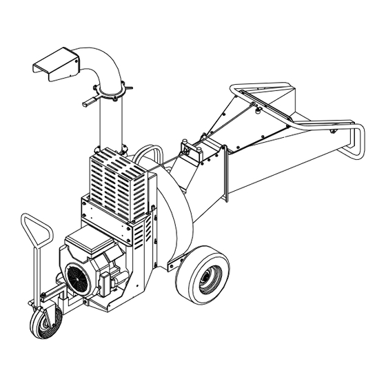
- Page 10 3. IDENTIFICATION OF THE MAIN PARTS 1. Loading hopper with guards 2. Tow bar 3. Petrol engine / Diesel engine / electric motor 4. Power takeoff for tractor 5. Wheels 6. Grinding chamber 7. Outlet pipe 8. Feed roller unit Fig.
-
Page 11: Correct Use Of The Machine
Stop the machine immediately if anyone approaches. The Caravaggi Bio 230 bio-shredder has been built to shred vegetable matter, leaves and wood up to 10 cm in diameter in the top hopper. The machine must never be used for any other purposes, such as breaking up bottles or tins. -
Page 12: Unpacking And Preparation
5. UNPACKING AND PREPARATION The Bio 230 bio-shredder may be arranged on pallets to facilitate handling and transport before installation. To transport the machine in these conditions it is indispensable to use a transpallet or the like with an overall load capacity of around 800 kilos. - Page 13 Hopper in the stowed position Fig. 5 Hopper Hopper hook Fig. 6...
-
Page 14: Technical Characteristics
6. TECHNICAL CHARACTERISTICS The EC identification plate is clearly visible on the Bio 230 bio-shredder (Fig. 7). In all communications with the manufacturer state the serial number on the identification plate. 25037 PONTOGLIO (BS) - VIA M. ADAMELLO, 20 TEL. 030 7470464 - FAX 030 7470004 - ITALY Fig. -
Page 15: Overall Dimensions
6.1 Overall dimensions Electric / Petrol version Length (mm): 2500 Width (mm): 990 Height (mm): 1920 Empty weight (kg.): ~ 350 (dB): 104 WA MAX Fig. 8 Electric / Petrol version Length (mm): 2500 Width (mm): 990 Height (mm): 1920 Empty weight (kg.): ~ 350 (dB): 104 WA MAX... - Page 16 Tractor Version Length (mm): 2500 Width (mm): 1170 Height (mm): 2270 Empty weight (kg.): ~ 350 (dB): 104 WA MAX Fig. 10...
-
Page 17: Safety Rules
7. SAFETY RULES This handbook contains rules on how to use the machine properly and details of the hazards that may be encountered. Besides following the rules, the operator should use the machine sensibly, based on his experience, and adopt all the necessary precautions to prevent accident or injury. - Page 18 Do not place any tools or other objects on the machine as they could damage it or injure the operator. Use only original spares provided by Caravaggi. Safety rules during operation Check the hopper is empty before starting up the machine.
- Page 19 7.2 SPECIFIC SAFETY AND ACCIDENT-PREVENTION RULES Petrol version 7.2.1 If there is a malfunction, and prior to any maintenance, adjustment and cleaning operations (e.g. removing foreign bodies from the hopper), switch off the motor and remove the spark plug cable. ...
- Page 20 7.2.3 Electric models Maintenance, adjustment and cleaning operations (e.g. removing foreign bodies from the hopper) must be done with the machine resting firmly on the ground, switched off and disconnected from the power supply. The machine complies with the general principles of electrical safety. This means that if any changes are made to the structure or components, this will alter the characteristics of the system, which will no longer comply with the safety requirements.
- Page 21 8. STARTING UP Caution! Before starting up the engine/motor check that the bio-shredder is on a stable surface and there are no animals or unauthorised persons in the work area. Read the engine manufacturer’s instruction book carefully. Check the oil and fuel levels and top up if necessary. 8.1 Petrol engine version ...
- Page 22 8.2 Electric motor version Make sure the mains voltage corresponds to the motor rated voltage (check the rating plate on the motor). Check that the power cable is connected, then press the start/stop button. Regularly check that the power cable is in perfect condition. Never repair a damaged cable with insulating tape or a thermal lamp.
- Page 23 Only use cardan shafts with integral guards. When the cardan shaft is disconnected from the power takeoff, it must always be placed on its support. Caravaggi declines all liability for damage or injury caused by incorrect installation and use of the cardan shaft. IMPORTANT At the end of the job, switch off the tractor and disconnect the cardan shaft from the power takeoff.
- Page 24 8.4 Operation The bio-shredder has been prepared correctly and is now ready to work. Upper hopper Before loading trimmings and foliage into the upper hopper, check the power rating of your particular model. (Fig. 14a). Important. Drop the material into the mouth of the hopper. Caution! Never insert the hands and arms in the hopper! To invert rotation of the feed roller, push the lever towards the hopper.
- Page 25 8.5 Rules to follow when moving the machine Stand at the side of the machine and make sure there is no one within the operating range. When the motor/engine has reached the maximum number of revs, operate the control button to move the machine in the desired direction (Fig.
-
Page 26: Maintenance
9. MAINTENANCE Caution! Before proceeding with any maintenance operations, switch off the engine/motor and make sure the machine cannot be started up. Safety gloves must be worn during maintenance operations. 9.1 Replacing the blades Unscrew the locking nuts and open the feed hopper (Fig. 17). ... - Page 27 Side chipping blade Central chipping blade Fig. 18 Fig. 19...
- Page 28 9.2 Replacing the counter-blades Unscrew the locking nuts and open the feed hopper (Fig. 17). Clean the hexagonal seat of the socket screws. Insert an Allen wrench right into the slot and tap lightly with a hammer. ...
- Page 29 9.3 Removing, inverting and replacing the knives Unscrew the locking nuts and open the feed hopper (Fig. 17). Pull the sieve out of the grinding chamber. Remove the central chipping blade and the aluminium cap. Unscrew the 6 screws and remove the front chipping disc. ...
- Page 30 9.4 Replacing the blades Important! Before doing this, remove the rotor from the shredding chamber and then take it apart. Unscrew the locking nuts and open the feed hopper (Fig. 17). Remove the sieve from the shredding chamber. ...
- Page 31 9.5 Replacing the sieve Unscrew the locking nuts and open the feed hopper (Fig. 17). Pull the sieve out of the grinding chamber. Insert a new sieve in the grinding chamber. Close the feed hopper and tighten the locking nuts. Sieve Fig.
- Page 32 9.6 Replacing and tensioning the belts 9.6.1 Replacing the belts Remove the pump guard and the front motor/engine block guard. Loosen the tensioning device screw to slacken the belt tension (Fig. 27). Remove the damaged or worn belts and mount new ones. ...
- Page 33 9.6.2 Tensioning the pump belt Remove the pump guard. Loosen the screws A of the pump support (Fig. 28). Loosen screw B of the tensioning device to adjust belt tension (Fig. 28). Tighten the screws A of the pump support. ...
- Page 34 9.6.3 Tensioning the rotor belts Remove the pump guard. Loosen the screws C of the motor/engine block (Fig. 29). Loosen the tensioning device screw A to adjust belt tensioning (Fig. 29). Tighten the screws C of the motor/engine block. ...
- Page 35 9.7 Replacing and topping up with hydraulic oil Remove the pump guard. Remove the cap from the oil tank (Fig. 30). oil tank cap Fig. 30 9.7.1 Changing the oil Unscrew the pipe at the bottom of the pump and drain all the oil out into the container (Fig.
- Page 36 Bottom pipe Fig. 31 maximum level Fig. 32...
- Page 37 air bleed Fig. 33 Recommended oil SAE 20 W20 (SAE 30) Shell Tellus TD 46 9.7.2 Topping up the hydraulic oil If the oil tank is empty or nearly empty, top up as follows. Fill with hydraulic oil to just below the maximum mark on the tank, with the engine cold.
- Page 38 9.8 Routine maintenance Beginning Before End of of season each job season Check engine oil level Check screws, tightness, casing, hopper, etc. Check belt tension and state of wear Check wear on knives ...
- Page 39 9.9 Programming and setting the No-Stress Plus device hour/rpm counter hours/minutes 4-digit display display instrument activation rpm/throttle MACCHINE INDUSTRIALI NO STRESS - PLUS display figure increment function key for figure selection key / settings and mode display confirmation Partial and total hour counter display ...
- Page 40 hour/rpm hours/minutes counter display 4-digit display instrument activation rpm/throttle MACCHINE INDUSTRIALI NO STRESS - PLUS display figure increment function key for figure selection key / settings and mode display confirmation Maximum threshold setting Switch on the machine and run it at the maximum number of revolutions. ...
-
Page 41: Troubleshooting Chart
10. TROUBLESHOOTING CHART Problem Solution The bio-shredder will Check belt tension and condition, PTO and gears. not start. Check to see if the pulleys are jammed. Check the knives, blade and counter-blade. Check to see if there is any material in the shredding chamber. Check the state of the engine/motor (consult the instruction manual supplied). -
Page 42: Warranty
If you find the Bio-Shredder is defective due to faulty materials or workmanship, send the Manufacturer a written claim. The procedure is as follows: 1. The machine must be returned to the Seller or the authorised CARAVAGGI importer. 2. A duly compiled warranty or, in its absence, the original receipt must be presented. - Page 43 NOTES ______________________________________________ ______________________________________________ ______________________________________________ ______________________________________________ ______________________________________________ ______________________________________________ ______________________________________________ ______________________________________________ ______________________________________________ ______________________________________________ ______________________________________________ ______________________________________________ ______________________________________________ ______________________________________________ ______________________________________________ ______________________________________________ ______________________________________________ ______________________________________________ ______________________________________________ ______________________________________________ ______________________________________________ ______________________________________________ ______________________________________________ ______________________________________________ ______________________________________________ ______________________________________________ ______________________________________________ ______________________________________________ ______________________________________________ ______________________________________________...
- Page 44 CARAVAGGI MACCHINE INDUSTRIALI S.r.l. 20 Via Monte Adamello 25037 Pontoglio (BS), ITALY Tel. (+39) 030 7470464 - Fax (+39) 030 7470004 Website www.caravaggi.com E-mail info@caravaggi.com Rev.1-2021...
Need help?
Do you have a question about the Bio 230 and is the answer not in the manual?
Questions and answers