Table of Contents
Advertisement
Quick Links
Advertisement
Table of Contents

Related Manuals for Alcatel-Lucent 7310


Summary of Contents for Alcatel-Lucent 7310
- Page 1 Alcatel-Lucent 7310 Metro Cell Cabinet Installation Manual...
- Page 2 7310 M LCATEL UCENT ETRO ABINET NSTALLATION ANUAL Document Information Identification Alcatel-Lucent 7310 Metro Cell Cabinet Installation Manual 1000023858 Rev 02 1/15...
- Page 3 ANUAL Before You Begin How to Get Assistance If you need help with your Alcatel-Lucent products, contact one of our TAC Engineers at 866-582-3688. Packaging Inspection If the shipping container shows evidence of rough handling, inspect the equipment carefully for shipping damage.
- Page 4 Failure to comply with these precautions or with specific warnings elsewhere in this manual risks personal injury and violates safety standards of design, manufacture, and intended use of the equipment. Alcatel-Lucent is not responsible for any equipment damage or poor operating performance when these guidelines are not followed or when noncertified installers perform the work.
- Page 5 7310 M LCATEL UCENT ETRO ABINET NSTALLATION ANUAL Type of Precaution Precaution Electrical Proper Ground The equipment must be connected to an electrical ground to minimize shock hazard. Consult NFPA 70 (NEC) and local codes for grounding requirements. Explosive Atmosphere Do not operate the equipment in the presence of flammable gases, fumes, or dust.
- Page 6 7310 M LCATEL UCENT ETRO ABINET NSTALLATION ANUAL The safety alert symbol is used on product labels and in this guide to alert the user to important operating and maintenance instructions.
-
Page 7: Table Of Contents
7310 M LCATEL UCENT ETRO ABINET NSTALLATION ANUAL Contents Introduction 1 Precautions 2 Threat Releases 2 Site Considerations 2 Thermal Clearance Supplied Items 4 Wiring Diagrams 4 Knockout Removal 5 Cable Access 5 Cabinet Mounting 5 Cabinet Lifting 6 Cabinet Weight 6... - Page 8 7310 M LCATEL UCENT ETRO ABINET NSTALLATION ANUAL viii...
-
Page 9: Introduction
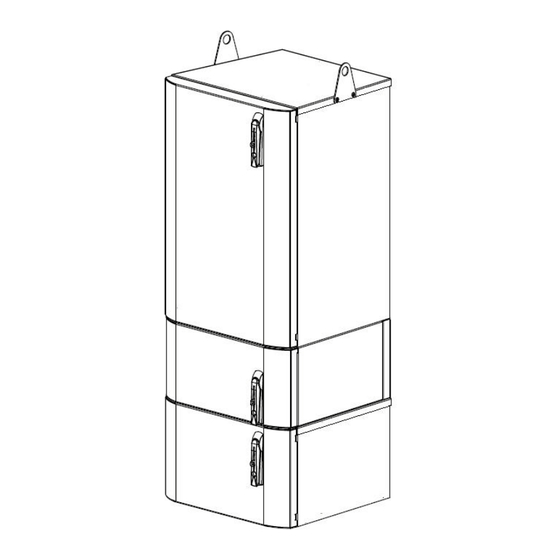
UCENT ETRO ABINET NSTALLATION ANUAL Introduction The 7310 Metro Cell cabinets power internally-mounted Metro Cells. The cabinets can be deployed quickly and mounted easily on a pad, wall, pole, or rooftop. PDU (not shown) Metro Cell B13 or AWS SAR-W... -
Page 10: Precautions
Threat Releases The on-site technician is responsible for acquiring threat releases before work begins. Neither Alcatel-Lucent nor its representatives will start any work without site management approval. Site Considerations A site must be accessible to equipment for installation, maintenance, and expansion. -
Page 11: Thermal Clearance
7310 M LCATEL UCENT ETRO ABINET NSTALLATION ANUAL Thermal Clearance WARNING Potential Equipment Damage! Following cabinet thermal requirements is critical. To avoid equipment damage, do not install the AC or DC metro cell cabinets onto a dark roof or dark wall. -
Page 12: Supplied Items
7310 M LCATEL UCENT ETRO ABINET NSTALLATION ANUAL Supplied Items IMPORTANT Do not store installation manual in cabinet after cabinet installation is complete. Items shipped with the MC-AR2, MC-AR3, MC-DBR4, or MC-DBR5 Metro Cell cabinets include: 3/16-in. Allen wrench ... -
Page 13: Knockout Removal
7310 M LCATEL UCENT ETRO ABINET NSTALLATION ANUAL Knockout Removal Cable Access Remove the knockouts for cable access before mounting the cabinet. The site plan should show which knockouts to remove for the customer’s configuration. Follow best practices to remove knockouts. -
Page 14: Cabinet Lifting
7310 M LCATEL UCENT ETRO ABINET NSTALLATION ANUAL Cabinet Lifting Determine a safe method of lifting the cabinet based on maximum weight. Use a portable lifting/supporting device to mount the cabinet to a pole, wall, H-frame, pad or platform necessary. -
Page 15: Cabinet Dimensions
7310 M LCATEL UCENT ETRO ABINET NSTALLATION ANUAL Cabinet Dimensions MC-AR2 and MC-AR3 Cabinet 19.92 3.29 23.25 (50.60) (8.36) (59.05) 30.00 Pole Mount (76.20) Front View Side View 44.28 44.54 (112.47) (113.13) Dimensions in inches (centimeters) External Pole Mount Top View... - Page 16 7310 M LCATEL UCENT ETRO ABINET NSTALLATION ANUAL MC-DBR4 and MC-DBR5 Cabinet 23.25 (59.06) 19.92 2.75 (50.60) (6.99) 53.19 52.44 (135.10) (133.19) Pole Mount (Optional) Front View Side View 42.81 44.00 (108.73) (111.76) Dimensions in inches (centimeters) External J-Box Pole Mount...
-
Page 17: Pole Mount
7310 M LCATEL UCENT ETRO ABINET NSTALLATION ANUAL Pole Mount Pole Mount Bracket Dimensions 49.655 1261.24 27.155 689.74 48.740 1238 26.205 665.61 .563 14.29 44.539 1131.29 .563 14.29 22.073 560.66 13.030 330.96 29.204 741.77 23.482 596.43 3.987 101.26 12.516 317.90 9.000 228.60... - Page 18 7310 M LCATEL UCENT ETRO ABINET NSTALLATION ANUAL Kit Contents MC-AR2 and MC-AR3 MC-DBR4 and MC-DBR5 (1) Pole mount bracket (1) Pole mount bracket (4) 3/8-16 x 7/8-in. long stainless (8) 3/8-16 x 7/8-in. long stainless ...
- Page 19 7310 M LCATEL UCENT ETRO ABINET NSTALLATION ANUAL Note The pole mount bracket “V” tabs should be positioned at the top for correct pole mount bracket orientation. “V” Tabs “V” Tabs Pole (2) Threaded Rod/Bolt Locations (4) Threaded Rod/Bolt Locations...
- Page 20 7310 M LCATEL UCENT ETRO ABINET NSTALLATION ANUAL Attach 1 set of customer-provided stainless steel hardware (size compatible with size of threaded rod or bolt: (1) 1 1/2-in. diameter load spreading washer, (1) split-lock washer, and (2) hex nuts) to each threaded rod or bolt, in the same stacking order (flat washer against the pole).
- Page 21 7310 M LCATEL UCENT ETRO ABINET NSTALLATION ANUAL Secure a mechanical lifting device to both lifting tabs and lift the cabinet. It is recommended that 2 independent lifting devices be used to connect to the lifting hoist. See cabinet lifting section.
- Page 22 7310 M LCATEL UCENT ETRO ABINET NSTALLATION ANUAL WARNING Do not release the cabinet from the mechanical lifting device until the cabinet is permanently secured to the pole mount bracket. This information is outlined on the next page. Do not stand underneath the cabinet until it is completely installed.
- Page 23 7310 M LCATEL UCENT ETRO ABINET NSTALLATION ANUAL Note Do not remove the rear bracket from the Metro Cell or SAR-W. Rear Equipment Mounting Bracket Hardware Location Note: Cabinet view is removed from pole to show hardware locations MC-AR2 and MC-AR3...
- Page 24 7310 M LCATEL UCENT ETRO ABINET NSTALLATION ANUAL Reposition each Metro Cell or SAR-W in its original orientation inside the cabinet. Retighten the hardware securing the rear equipment bracket to the cabinet.Torque hardware to 30 in-lb. WARNING Failure to install all pole mount bracket mounting hardware could result in serious injury or death.
- Page 25 7310 M LCATEL UCENT ETRO ABINET NSTALLATION ANUAL Install 2 hardware stack-ups as illustrated. Install 2 Hardware Stack-ups Equipment Compartment Bolt Split Flat Hardware Stack-up Cabinet Pole Mount Back Wall Bracket Note: Cabinet is shown Rectifier with pole and equipment removed...
- Page 26 7310 M LCATEL UCENT ETRO ABINET NSTALLATION ANUAL Install 4 hardware stack-ups as illustrated. Bolt Split Flat Hardware Stack-up Cabinet Pole Mount Back Wall Bracket Note: Cabinet is shown Rectifier with pole and equipment removed Compartment to show hardware locations...
- Page 27 7310 M LCATEL UCENT ETRO ABINET NSTALLATION ANUAL Pull each Metro Cell or SAR-W down to allow access to the cabinet’s rear wall and the pole mount bracket mounting locations. Install 2 remaining hardware stack-ups as illustrated. Bolt Split Flat...
- Page 28 7310 M LCATEL UCENT ETRO ABINET NSTALLATION ANUAL Install (4) pallet/plinth mounting bolt hole plugs (included inside the cabinet) into the pallet/plinth bolt holes located on the bottom of the battery base. Bolt Hole Locations Note: Cabinet view is removed...
- Page 29 7310 M LCATEL UCENT ETRO ABINET NSTALLATION ANUAL Note The pole mount bracket “V” tabs should be positioned at the top for correct pole mount bracket orientation. “V” Tabs “V” Tabs Banding Banding Locations Locations Banding Banding Locations Locations MC-AR2 and MC-AR3...
-
Page 30: Wall Or H-Frame Mount
7310 M LCATEL UCENT ETRO ABINET NSTALLATION ANUAL Wall or H-frame Mount Tools and Materials Required Standard tools, including a nut driver A load-bearing wall or H-frame structure that meets local codes and ordinances for this category and weight of cabinet Securing hardware specific to the wall construction and cabinet weight, determined and ... - Page 31 7310 M LCATEL UCENT ETRO ABINET NSTALLATION ANUAL Note The pole mount bracket “V” tabs should be positioned at the top for correct pole mount bracket orientation. “V” Tabs “V” Tabs Wall Hardware Mounting Holes (12) Hardware Mounting Holes MC-AR2 and MC-AR3...
- Page 32 7310 M LCATEL UCENT ETRO ABINET NSTALLATION ANUAL ≡≡ To mount the cabinet to the pole mount bracket Insert 2 stainless steel 1/4-20 bolts (provided) into rear of cabinet in locations illustrated. Leave 1/4-in. gap from back face of cabinet to underside of bolt. The bolts are used to hold the cabinet onto the pole mount bracket while correct cabinet alignment is determined.
- Page 33 7310 M LCATEL UCENT ETRO ABINET NSTALLATION ANUAL Secure a mechanical lifting device to both lifting tabs and lift the cabinet. It is recommended that 2 independent lifting devices be used to connect to the lifting hoist. See cabinet lifting section.
- Page 34 7310 M LCATEL UCENT ETRO ABINET NSTALLATION ANUAL WARNING Do not release the cabinet from the mechanical lifting device until the cabinet is permanently secured to the wall or H-frame. This information is outlined on the next page. ≡≡ To secure the MC-AR2 and MC-AR3 cabinet to the pole mount bracket Open the cabinet door.
- Page 35 7310 M LCATEL UCENT ETRO ABINET NSTALLATION ANUAL Note Do not remove the rear bracket from the Metro Cell or SAR-W. Rear Equipment Mounting Bracket Hardware Location Note: Cabinet view is removed from pole to show hardware locations MC-AR2 and...
- Page 36 7310 M LCATEL UCENT ETRO ABINET NSTALLATION ANUAL Reposition each Metro Cell or SAR-W in its original orientation inside the cabinet. Retighten the hardware securing the rear equipment bracket to the cabinet.Torque hardware to 30 in-lb. WARNING Failure to install all pole mount bracket mounting hardware could result in serious injury or death.
- Page 37 7310 M LCATEL UCENT ETRO ABINET NSTALLATION ANUAL Install 2 hardware stack-ups as illustrated. Install 2 Hardware Stack-ups Equipment Compartment Bolt Split Flat Hardware Stack-up Cabinet Pole Mount Back Wall Bracket Note: Cabinet is shown Rectifier with pole and equipment removed...
- Page 38 7310 M LCATEL UCENT ETRO ABINET NSTALLATION ANUAL Install 4 hardware stack-ups as illustrated. MC-DBR4 and MC-DBR5 Cabinet Bolt Split Flat Hardware Stack-up Cabinet Pole Mount Back Wall Bracket Note: Cabinet is shown Rectifier with pole and equipment removed Compartment...
- Page 39 7310 M LCATEL UCENT ETRO ABINET NSTALLATION ANUAL Pull each Metro Cell or SAR-W down to allow access to the cabinet’s rear wall and the pole mount bracket mounting locations. Install 2 remaining hardware stack-ups as illustrated. Bolt Split Flat...
-
Page 40: Pad/Rooftop Mount
7310 M LCATEL UCENT ETRO ABINET NSTALLATION ANUAL Install (4) pallet/plinth mounting bolt hole plugs (included inside the cabinet) into the pallet/plinth bolt holes located on the bottom of the battery base. Bolt Hole Locations Note: Cabinet view is removed... - Page 41 7310 M LCATEL UCENT ETRO ABINET NSTALLATION ANUAL Kit Contents (1) 4-in. plinth (1) Front plinth cover (1) Rear plinth cover (12) 1/4-20 stainless steel security screws (12) 1/4-in. stainless steel split-lock washers (12) 1/4-in. stainless steel flat washers ...
- Page 42 7310 M LCATEL UCENT ETRO ABINET NSTALLATION ANUAL Secure the plinth with appropriate anchoring hardware. Ensure load spreading washers are oriented as illustrated. Torque hardware per anchor nut specifications. Mounting Mounting Hole Hole Anchoring Hardware Load Spreading Washer Mounting Mounting...
- Page 43 7310 M LCATEL UCENT ETRO ABINET NSTALLATION ANUAL Plinth-to-cabinet Hardware Securing Locations ≡≡ To access the plinth-to-cabinet hardware securing locations for the MC-AR2 and MC-AR3 cabinet: Open the cabinet door. Inside the cabinet, loosen the hardware securing the rear equipment mounting bracket to the cabinet.
- Page 44 7310 M LCATEL UCENT ETRO ABINET NSTALLATION ANUAL Secure the cabinet to the plinth with 1 hardware stackup (included with the kit) in each corner: (1) 3/8-16 stainless steel bolt, (2) 3/8-in. stainless steel flat washers, (1) 3/8-in. stainless steel split-lock washer, and (1) 3/8-in. stainless steel nut). Torque hardware to 20 ft-lb.
- Page 45 7310 M LCATEL UCENT ETRO ABINET NSTALLATION ANUAL Secure the cabinet to the plinth with 1 hardware stackup (included with the kit) in each corner: (1) 3/8-16 stainless steel bolt, (2) 3/8-in. stainless steel flat washers, (1) 3/8-in. stainless steel split-lock washer, and (1) 3/8-in. stainless steel nut). Torque hardware to 20 ft-lb.
-
Page 46: Grounding
7310 M LCATEL UCENT ETRO ABINET NSTALLATION ANUAL Grounding Tools and Materials Required Standard tools, including 7/16 in. nut driver Corrosion inhibiting, electrically conductive grease Customer-supplied ground cable with a 2-hole lug connector (1/4 in. diameter holes, ... - Page 47 7310 M LCATEL UCENT ETRO ABINET NSTALLATION ANUAL ≡≡ To install RF cables Test RF cables and antennas per local practices. Install all antennas and route RF cables to the designated locations on the cabinet bulkheads. Remove protective caps from antenna ports.
-
Page 48: Batteries (Mc-Dbr4 And Mc-Dbr5 Only)
7310 M LCATEL UCENT ETRO ABINET NSTALLATION ANUAL Batteries (MC-DBR4 and MC-DBR5 Only) WARNING High Energy Level! Failure to follow safety procedures could result in severe injury! When installing or servicing the batteries, use certified insulated tools to prevent electrical ... - Page 49 7310 M LCATEL UCENT ETRO ABINET NSTALLATION ANUAL Remove the battery covers from the negative terminal end of batteries 1 - 3. Refer to illustration below for battery string connection information. 80AHr Battery SAFT Tel X80 38 Cells TEMP PROBE...
- Page 50 7310 M LCATEL UCENT ETRO ABINET NSTALLATION ANUAL Position battery 1 as illustrated with positive battery terminal end facing forward. Battery 1 Remove battery cover from positive terminal end of battery 1. Install positive battery cable from power shelf onto battery 1 positive terminal. Replace battery cover. Push battery 1 into...
- Page 51 7310 M LCATEL UCENT ETRO ABINET NSTALLATION ANUAL Position battery 2 as illustrated with positive battery terminal end facing forward. Battery 1 Battery 2 Remove battery cover from positive terminal end of battery 1. Install the negative battery cable from battery 1 onto the positive battery terminal on battery 2. Replace battery cover.
- Page 52 7310 M LCATEL UCENT ETRO ABINET NSTALLATION ANUAL Dress battery cable as illustrated. Battery Cable Routed Through Trough Battery Cable Dressed Correctly Important: Verify that the cable is also bent downward at the rear connection The cable should route into...
- Page 53 7310 M LCATEL UCENT ETRO ABINET NSTALLATION ANUAL Remove battery cover from positive terminal end of battery 3. Install the negative battery cable from battery 2 onto the positive battery terminal on battery 3. Replace battery cover. Push battery 3 into position.
- Page 54 7310 M LCATEL UCENT ETRO ABINET NSTALLATION ANUAL Position battery 4 as illustrated with negative battery terminal end facing forward. Remove battery cover from positive terminal end of battery 4. Install the negative battery cable from battery 3 onto the positive battery terminal on battery 4. Replace battery cover.
-
Page 55: Connecting Ac Power
7310 M LCATEL UCENT ETRO ABINET NSTALLATION ANUAL Push battery 4 into position. Using a 7/16 in. nut driver, re-install the battery retention bracket and secure with the 2 bolts removed in Step 1. Torque to 85 in-lb. Battery Retention Bracket... - Page 56 7310 M LCATEL UCENT ETRO ABINET NSTALLATION ANUAL ≡≡ To connect the cabinet to AC power Use the Torx T15 security bit (included in the cabinet) to remove the 2 stainless steel 6-32x1/2-in. security screws securing the exterior j-box cover. Remove and retain the cover and hardware.
- Page 57 7310 M LCATEL UCENT ETRO ABINET NSTALLATION ANUAL Ensure j-box ground cable is connected with incoming AC and cabinet ground cables. J-box Ground Cable Wing-nut AC and Cabinet Ground Cables Connect the 3/4 NFT conduit fitting and 3/4-in. conduit to the external j-box.
-
Page 58: Connecting The Backhaul Fiber Cable
7310 M LCATEL UCENT ETRO ABINET NSTALLATION ANUAL Reinstall the external j-box cover and secure with the 2 security screws. Hand-tighten screws. Connecting the Backhaul Fiber Cable Tools and Materials Required Standard tools, including antistatic wrist strap and any tools to seal conduit ... - Page 59 7310 M LCATEL UCENT ETRO ABINET NSTALLATION ANUAL Inside the cabinet, use a 3/16-in. Allen wrench to loosen the hardware securing the rear equipment mounting bracket to the cabinet. Note Do not remove the rear bracket from the Metro Cell or SAR-W.
- Page 60 7310 M LCATEL UCENT ETRO ABINET NSTALLATION ANUAL Note Keep nut loose until correct cable length is established. Seal SAR-W Gland Fiber cable inserted through Full AXS SAR-W gland Secure the fiber cable to the cable management tray using cable ties. Ensure there is enough service loop for the SAR-W to pivot without stressing the fiber cable or the FullAXS SAR-W gland.
-
Page 61: Alarm Configuration
Alarm Configuration IMPORTANT Please refer to the Alcatel-Lucent OLCS website shown below for copies of the 7310 Metro Cell cabinet alarming procedures or contact your local representative. All 7310 Metro Cell cabinet alarming procedures can be downloaded from the following Alcatel-Lucent OLCS website location: https://infoproducts.alcatel-lucent.com/aces/cgi-bin/dbaccessproddoc.cgi.edit?entryId=... - Page 62 7310 M LCATEL UCENT ETRO ABINET NSTALLATION ANUAL Cabinet Alarms (MC-DBR4 and MCDBR5 Only) The GE-J2007003 L202 SPS rectifier shelf supports 9 binary alarm inputs with a common return (Pin 6). The signal assignment for alarm input connector J1 (located on the front face of the GE-J2007003 L202 SPS rectifier shelf ) with the SPS841A_910R_USB with factory default assignments is shown below.
- Page 63 7310 M LCATEL UCENT ETRO ABINET NSTALLATION ANUAL The Pulsar Edge controller supports network access to almost all controller functions including all voltage and temperature readings, current alarms, and alarm history. It supports a web-based user interface using standard browsers like Microsoft Internet Explorer©. It can provide plant...
-
Page 64: Commissioning The Equipment
ETRO ABINET NSTALLATION ANUAL Commissioning the Equipment Name Part Number Alcatel-Lucent 9764 Metro Cell Outdoor V1.0 2x5W B13 LTE Hardware 3MN-01714-0002-RJZZA Installation Document Alcatel-Lucent 7705 Service Aggregation Router, Release 6.0 R2, 3HE-07727-AAAB-TQZZA SAR-W Chassis Installation Guide Rectifiers and Alarms ≡≡... - Page 65 7310 M LCATEL UCENT ETRO ABINET NSTALLATION ANUAL Use a Phillips screwdriver to tighten the captive screws on each rectifier. Captive Screws Observe each rectifier — a green LED light indicates the cabinet is powered and operating normally. Mgmt Rectifier...
-
Page 66: Sar-W
7310 M LCATEL UCENT ETRO ABINET NSTALLATION ANUAL SAR-W ≡≡ To commission the SAR-W Open the cabinet door. Use a torx driver to remove the 2 torx screws securing the access cover on the SAR-W. Remove the access cover. Mgmt... - Page 67 7310 M LCATEL UCENT ETRO ABINET NSTALLATION ANUAL Note Do not remove the rear bracket from the Metro Cell. Rear Equipment Mounting Bracket Hardware Locations Note 1: Cabinet view is removed from pole to show hardware locations Note 2: MC-DBR4 and MC-DBR5 cabinet...
-
Page 68: Connecting Power To Metro Cell 2 And External Nid
7310 M LCATEL UCENT ETRO ABINET NSTALLATION ANUAL Refer to the Metro Cell manufacturer’s manual for information on how to finalize the equipment commissioning process. Connecting Power to Metro Cell 2 and External NID NID Electrical Specifications NID maximum power = 25W... - Page 69 7310 M LCATEL UCENT ETRO ABINET NSTALLATION ANUAL Remove the compression nut and tube. LABEL 1 Plug Label Identifying Compression Tube Metro Cell 2 or NID Power Remove the sealing plug from the in-line connector and discard. Select the correct combination of seals for the cable type used.
-
Page 70: Maintenance
ABINET NSTALLATION ANUAL Associated Kits Name Part Number Alcatel-Lucent 7310 DC Metro Cell AWS (B4) Kit 3MV00489AC Alcatel-Lucent 7310 AC Metro Cell AWS (B4) Kit 3MV00489AB Alcatel-Lucent 7310 MC DC Cabinet Fan Kit 3MV00491AA Alcatel-Lucent 7310 MC AC Cabinet Fan Kit... - Page 71 7310 M LCATEL UCENT ETRO ABINET NSTALLATION ANUAL Note Do not remove the rear bracket from the SAR-W. Rear Equipment Mounting Bracket Hardware Locations Note 1: Cabinet view is removed from pole to show hardware locations Note 2: MC-DBR4 and MC-DBR5 cabinet...
- Page 72 7310 M LCATEL UCENT ETRO ABINET NSTALLATION ANUAL Disconnect the tether/link from the SAR-W. Tether/Link Return the SAR-W to its upright position inside the cabinet. Remove the 2 screws securing the retainer bracket. Retainer Bracket...
- Page 73 7310 M LCATEL UCENT ETRO ABINET NSTALLATION ANUAL WARNING The SAR-W is now unsecured. Carefully tip the SAR-W forward and lift out of the cabinet. Position the SAR-W on a flat surface. Use a 13mm socket to remove the 2 bolts securing...
- Page 74 7310 M LCATEL UCENT ETRO ABINET NSTALLATION ANUAL Use a 13mm socket to remove the 2 bolts securing the rear mounting bracket. Install the front and rear mounting brackets onto the new SAR-W and torque bolts to industry standards. Install the new SAR-W into the cabinet and reconnect all hardware and cables by reversing the previous SAR-W removal steps.
- Page 75 7310 M LCATEL UCENT ETRO ABINET NSTALLATION ANUAL Using the attached handle, pull down the Metro Cell. WARNING Do not pull down on the RF cables. Disconnect the 2 Metro Cell antenna cables and the GPS cable from the Metro Cell.
- Page 76 7310 M LCATEL UCENT ETRO ABINET NSTALLATION ANUAL Disconnect the ground and DC power cables from the Metro Cell. Ground Cable DC Power Cable Fiber Cable Use a torx wrench to remove the 3 torx security screws securing the access door on the Metro Cell.
- Page 77 7310 M LCATEL UCENT ETRO ABINET NSTALLATION ANUAL Disconnect the tether from the Metro Cell. Tether Return the Metro Cell to its upright position inside the cabinet. Remove the 2 screws securing the retainer bracket. Retainer Bracket...
- Page 78 7310 M LCATEL UCENT ETRO ABINET NSTALLATION ANUAL WARNING The Metro Cell is now unsecured. Carefully tip the Metro Cell forward and lift out of the cabinet.
- Page 79 7310 M LCATEL UCENT ETRO ABINET NSTALLATION ANUAL Position the Metro Cell on a flat surface. Use a Phillips screwdriver to remove the 5 stainless steel M5 flathead screws and a 13mm socket to remove the 2 stainless steel M8 x 30mm bolts securing the front mounting bracket.
- Page 80 7310 M LCATEL UCENT ETRO ABINET NSTALLATION ANUAL FRU Kits/MC-AR2 Cabinet Field Replaceable Items Description ALU Part No. Metro Cell 1 RF Cable to Bulkhead (TXRX1) PURC-2000003260 (Not Shown) Metro Cell 1 RF Cable to Bulkhead (TXRX2) PURC-2000003261 (Not Shown)
- Page 81 7310 M LCATEL UCENT ETRO ABINET NSTALLATION ANUAL FRU Kits/MC-AR2 Cabinet (continued) Field Replaceable Items Description ALU Part No. GPS Splitter PURC-2000002915 Cabinet Door PURC-2000003083 Door Alarm Harness PURC-2000002921 Techno 4-way Connector PURC-2000003084 Techno/PDU Power Cable (Not Shown) PURC-2000002923 AC Metro Cell...
- Page 82 7310 M LCATEL UCENT ETRO ABINET NSTALLATION ANUAL FRU Kits/MC-AR3 Cabinet Field Replaceable Items Description ALU Part No. Metro Cell 1 RF Cable to Diplexer (TXRX1) PURC-2000002880 (Not Shown) Metro Cell 1 RF Cable to Diplexer (TXRX2) PURC-2000002881 (Not Shown)
- Page 83 7310 M LCATEL UCENT ETRO ABINET NSTALLATION ANUAL FRU Kits/MC-AR3 Cabinet (continued) Field Replaceable Items Description ALU Part No. Lifting Tabs PURC-2000002913 Diplexer PURC-2000002914 GPS Splitter PURC-2000002915 Cabinet Door PURC-2000003083 Door Alarm Harness PURC-2000002921 Techno 4-way Connector PURC-2000003084 Techno/PDU Power Cable (Not Shown)
- Page 84 7310 M LCATEL UCENT ETRO ABINET NSTALLATION ANUAL FRU Kits/MC-DBR4 Cabinet Field Replaceable Items Description ALU Part No. Metro Cell 1 RF Cable to Diplexer (TXRX1) PURC-2000002880 (Not Shown) Metro Cell 1 RF Cable to Diplexer (TXRX2) PURC-2000002881 (Not Shown)
- Page 85 7310 M LCATEL UCENT ETRO ABINET NSTALLATION ANUAL FRU Kits/MC-DBR4 Cabinet (continued) Field Replaceable Items Description ALU Part No. GE DC Power Plant PURC-2000002897 GE DC Power Plant Controller (Not Shown) PURC-2000003393 GE DC Power Plant Rectifier (Not Shown PURC-2000002899...
- Page 86 7310 M LCATEL UCENT ETRO ABINET NSTALLATION ANUAL FRU Kits/MC-DBR5 Cabinet Field Replaceable Items Description ALU Part No. Metro Cell 1 RF Cable to Bulkhead (TXRX1) PURC-2000003260 (Not Shown) Metro Cell 1 RF Cable to Bulkhead (TXRX2) PURC-2000003261 (Not Shown)
- Page 87 7310 M LCATEL UCENT ETRO ABINET NSTALLATION ANUAL FRU Kits/MC-DBR5 Cabinet (continued) Field Replaceable Items Description ALU Part No. GE DC Power Plant Rectifier (Not Shown PURC-2000002899 AC SPD PURC-2000002900 DC SPD PURC-2000002901 Fiber Cable, SAR-W to Metro Cell (Not...
-
Page 88: Rf Wiring Diagram - Mc-Ar3/Mc-Dbr4
7310 M LCATEL UCENT ETRO ABINET NSTALLATION ANUAL RF Wiring Diagram — MC-AR3/MC-DBR4... -
Page 89: Rf Wiring Diagram - Mc-Ar2/Mc-Dbr5
7310 M LCATEL UCENT ETRO ABINET NSTALLATION ANUAL RF Wiring Diagram — MC-AR2/MC-DBR5... -
Page 90: Ac Wiring Diagram - Mc-Dbr4/Mc-Dbr5
7310 M LCATEL UCENT ETRO ABINET NSTALLATION ANUAL AC Wiring Diagram — MC-DBR4/MC-DBR5... -
Page 91: Ground Wiring Diagram - Mc-Dbr4/Mc-Dbr5
7310 M LCATEL UCENT ETRO ABINET NSTALLATION ANUAL Ground Wiring Diagram — MC-DBR4/MC-DBR5... -
Page 92: Dc/Data/Alarm Wiring Diagram - Mc-Dbr4/Mc-Dbr5
7310 M LCATEL UCENT ETRO ABINET NSTALLATION ANUAL DC/Data/Alarm Wiring Diagram — MC-DBR4/MC-DBR5... -
Page 93: Ground Wiring Diagram - Mc-Ar2/Mc-Ar3 Cabinet
7310 M LCATEL UCENT ETRO ABINET NSTALLATION ANUAL Ground Wiring Diagram — MC-AR2/MC-AR3 Cabinet... -
Page 94: Ac/Data/Alarm Wiring Diagram - Mc-Ar2/Mc-Ar3 Cabinet
7310 M LCATEL UCENT ETRO ABINET NSTALLATION ANUAL AC/Data/Alarm Wiring Diagram — MC-AR2/MC-AR3 Cabinet... - Page 95 7310 M LCATEL UCENT ETRO ABINET NSTALLATION ANUAL...
- Page 96 7310 M LCATEL UCENT ETRO ABINET NSTALLATION ANUAL...
Need help?
Do you have a question about the 7310 and is the answer not in the manual?
Questions and answers