Table of Contents
Advertisement
Available languages
Available languages
Quick Links
LOV TO ELECTRIC S.P. .
24020 GORLE (BERGAMO) ITALIA
VIA DON E. MAZZA, 12
TEL. 035 4282111
L
E
E-mail info@
ovato
lectric.com
L
E
Web
www.
ovato
lectric.com
W RNING!
– Carefully read the manual before the installation or use.
– This equipment is to be installed by qualified personnel, complying to current standards, to avoid
damages or safety hazards.
– Before any maintenance operation on the device, remove all the voltages from measuring and supply inputs and short-
circuit the CT input terminals.
– The manufacturer cannot be held responsible for electrical safety in case of improper use of the equipment.
– Products illustrated herein are subject to alteration and changes without prior notice. Technical data and descriptions in
the documentation are accurate, to the best of our knowledge, but no liabilities for errors, omissions or contingencies
arising there from are accepted.
– A circuit breaker must be included in the electrical installation of the building. It must be installed close by the
equipment and within easy reach of the operator. It must be marked as the disconnecting device of the equipment:
IEC/EN/BS 61010-1 § 6.11.3.1.
– Clean the device with a soft dry cloth; do not use abrasives, liquid detergents or solvents.
TTENTION !
– Lire attentivement le manuel avant toute utilisation et installation.
– Ces appareils doivent être installés par un personnel qualifié, conformément aux normes en vigueur en
matière d'installations, afin d'éviter de causer des dommages à des personnes ou choses.
– Avant toute intervention sur l'instrument, mettre les entrées de mesure et d'alimentation hors tension et court-circuiter
les transformateurs de courant.
– Le constructeur n'assume aucune responsabilité quant à la sécurité électrique en cas d'utilisation impropre du
dispositif.
– Les produits décrits dans ce document sont susceptibles d'évoluer ou de subir des modifications à n'importe quel
moment. Les descriptions et caractéristiques techniques du catalogue ne peuvent donc avoir aucune valeur
contractuelle.
– Un interrupteur ou disjoncteur doit être inclus dans l'installation électrique du bâtiment. Celui-ci doit se trouver tout
près de l'appareil et l'opérateur doit pouvoir y accéder facilement. Il doit être marqué comme le dispositif d'interruption
de l'appareil : IEC/EN/BS 61010-1 § 6.11.3.1.
– Nettoyer l'appareil avec un chiffon doux, ne pas utiliser de produits abrasifs, détergents liquides ou solvants.
CHTUNG!
– Dieses Handbuch vor Gebrauch und Installation aufmerksam lesen.
– Zur Vermeidung von Personen- und Sachschäden dürfen diese Geräte nur von qualifiziertem
Fachpersonal und unter Befolgung der einschlägigen Vorschriften installiert werden.
– Vor jedem Eingriff am Instrument die Spannungszufuhr zu den Messeingängen trennen und die Stromwandler
kurzschlie en.
– Bei zweckwidrigem Gebrauch der Vorrichtung übernimmt der Hersteller keine Haftung für die elektrische Sicherheit.
– Die in dieser Broschüre beschriebenen Produkte können jederzeit weiterentwickelt und geändert werden. Die im Katalog
enthaltenen Beschreibungen und Daten sind daher unverbindlich und ohne Gewähr.
– In die elektrische Anlage des Gebäudes ist ein Ausschalter oder Trennschalter einzubauen. Dieser muss sich in
unmittelbarer Nähe des Geräts befinden und vom Bediener leicht zugänglich sein. Er muss als Trennvorrichtung für das
Gerät gekennzeichnet sein: IEC/EN/BS 61010-1 § 6.11.3.1.
– Das Gerät mit einem weichen Tuch reinigen, keine Scheuermittel, Flüssigreiniger oder Lösungsmittel verwenden.
DVERTENCI
– Leer atentamente el manual antes de instalar y utilizar el regulador.
– Este dispositivo debe ser instalado por personal cualificado conforme a la normativa de instalación
vigente a fin de evitar daños personales o materiales.
– Antes de realizar cualquier operación en el dispositivo, desconectar la tensión de las entradas de alimentación y medida,
y cortocircuitar los transformadores de corriente.
– El fabricante no se responsabilizará de la seguridad eléctrica en caso de que el dispositivo no se utilice de forma
adecuada.
– Los productos descritos en este documento se pueden actualizar o modificar en cualquier momento. Por consiguiente,
las descripciones y los datos técnicos aquí contenidos no tienen valor contractual.
– La instalación eléctrica del edificio debe disponer de un interruptor o disyuntor. Éste debe encontrarse cerca del
dispositivo, en un lugar al que el usuario pueda acceder con facilidad. Además, debe llevar el mismo marcado que el
interruptor del dispositivo (IEC/EN/BS 61010-1 § 6.11.3.1).
– Limpiar el dispositivo con un trapo suave; no utilizar productos abrasivos, detergentes líquidos ni disolventes.
UPOZORNĚNÍ
AVERTIZARE!
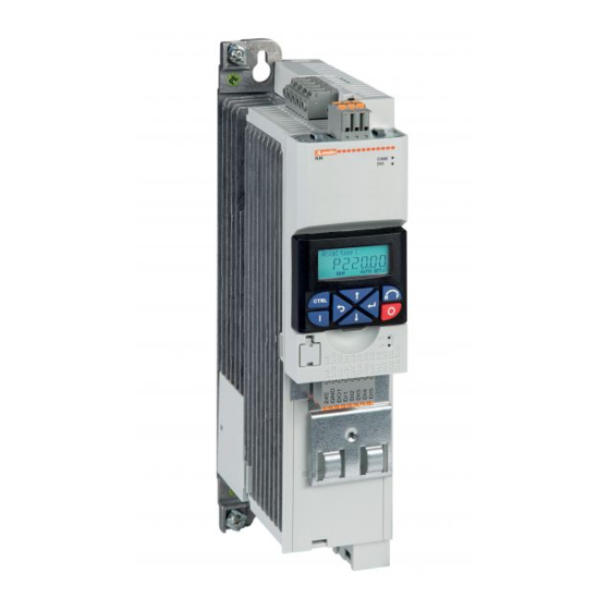
GB V RI BLE SPEED DRIVES
Installation manual
I
ZION MENTI
VELOCITÀ V RI BILE
Manuale di installazione
VLB...
TTENZIONE!
– Leggere attentamente il manuale prima dell'utilizzo e l'installazione.
– Questi apparecchi devono essere installati da personale qualificato, nel rispetto delle vigenti normative
impiantistiche, allo scopo di evitare danni a persone o cose.
– Prima di qualsiasi intervento sullo strumento, togliere tensione dagli ingressi di misura e di alimentazione e
cortocircuitare i trasformatori di corrente.
– Il costruttore non si assume responsabilità in merito alla sicurezza elettrica in caso di utilizzo improprio del dispositivo.
– I prodotti descritti in questo documento sono suscettibili in qualsiasi momento di evoluzioni o di modifiche. Le
descrizioni ed i dati a catalogo non possono pertanto avere alcun valore contrattuale.
– Un interruttore o disgiuntore va compreso nell'impianto elettrico dell'edificio. Esso deve trovarsi in stretta vicinanza
dell'apparecchio ed essere facilmente raggiungibile da parte dell'operatore. Deve essere marchiato come il dispositivo di
interruzione dell'apparecchio: IEC/EN/BS 61010-1 § 6.11.3.1.
– Pulire l'apparecchio con panno morbido, non usare prodotti abrasivi, detergenti liquidi o solventi.
UW G !
ПРЕДУПРЕЖДЕНИЕ!
DİKKAT!
UPOZORENJE!
G
B
1
Advertisement
Chapters
Table of Contents

Related Manuals for LOVATO ELECTRIC VLB Series


Summary of Contents for LOVATO ELECTRIC VLB Series
- Page 1 GB V RI BLE SPEED DRIVES Installation manual ZION MENTI VELOCITÀ V RI BILE LOV TO ELECTRIC S.P. . Manuale di installazione 24020 GORLE (BERGAMO) ITALIA VIA DON E. MAZZA, 12 TEL. 035 4282111 E-mail info@ ovato lectric.com www. ovato lectric.com VLB...
-
Page 2: Table Of Contents
CONTENTS Safety information ......................................... Residual hazards ..................................................Intended use ....................................................Product description ....................................... Electrical installation ......................................Important notes .................................................... Protection with fuses, circuit breaker, RCD ..........................................Connection according to UL ................................................. Connection diagram ..................................................EMC-compliant installation ................................................Terminal data ....................................................DC-Bus voltage operative range .............................................. - Page 3 1 S FETY INFORM TION 1.1 RESIDUAL HAZARDS The user must take the residual hazards mentioned into consideration in the risk assessment for his/her machine/system. If the above is disregarded, this can lead to severe injuries to persons and damage to material assets! PRODUCT Observe the warning labels on the product! ICON...
- Page 4 CONNECTION TO THE IT SYSTEM Examples: Internal components have earth/ground potential. Possible consequence: The monitoring devices of the IT system will be triggered. – Upstream an isolation transformer. – Before connection to an IT system be absolutely sure to remove the screws labeled with "IT"...
-
Page 5: Electrical Installation
3 ELECTRIC L INST LL TION 3.1 IMPORTANT NOTES DANGER! Electrical voltage Possible consequences: Death or severe injuries. – Any work on the inverter must only be carried out in the deenergised state. – Inverter up to 45kW: After switching off the mains voltage, wait for at least 3 min before you start working. –... - Page 6 3.3 CONNECTION ACCORDING TO UL WARNING! – The integral solid state short circuit protection included in the inverter does not provide branch circuit protection. Branch circuit protection must be provided in accordance with the National Electrical Code /Canadian Electrical Code and any additional local codes. –...
- Page 7 SUGGESTED BCP FUSES Manufacturer Max. rated current [A] Designation Eaton/Bussmann FWP-6A14F FWP-15B, FWP-15A14F 170M1309, 170M1359, 170M1409 FWP-20B, FWP-20A14F 170M1310, 170M1360, 170M1410 FWP-40A22F, FWP-40B, FWP-40A14F, FWP-40A 170M1313, 170M1363, 170M1413 FWP-50A22F, FWP-50B, FWP-50A14F, FWP-50A 170M1314, 170M1364, 170M1414 FWP-63A22F, FWP-60B, FWP-60A 170M1315, 170M1365, 170M1415 FWP-80A22F, FWP-80B, FWP-80A 170M1316, 170M1366, 170M1416 FWP-100A22F, FWP-100B, FWP-100A...
-
Page 8: Connection Diagram
3.4 CONNECTION DIAGRAM Thernal Brake contact / resistor 3.5 EMC-COMPLIANT INSTALLATION The system of drive and motor comply with the EMC Directive 2014/30/EU if they are installed according to the specifications of CE-typical drive systems. These guidelines should also be followed in installations requiring FCC Part 15 or ICES 001 compliance. -
Page 9: Terminal Data
3.6 TERMINAL DATA Rated power 0.4...2.2 7.5...11 15...30 37...45 55...75 90...110 Connection description Mains connection Connection X100 Connection type Pluggable Non-pluggable Max. cable cross-section mm² Stripping length 0.35 0.43 0.87 1.26 Tightening torque lb-in Required tool Screwdriver 0.5 x 3.0 Screwdriver Screwdriver Screwdriver... -
Page 10: Data Of Control Terminals
DATA OF CONTROL TERMINALS Control terminal X3 Inputs/outputs Terminal Description Digital inputs DI1, DI2, DI3, DI4, DI5 DI3/DI4 can be optionally used as frequency or encoder input. HIGH active/LOW active switchable. Digital outputs Analog inputs AI1, AI2 Can be optionally used as voltage or current input. Analog outputs Can be optionally used as voltage or current output. - Page 11 ANALOG INPUTS Cycle time Resolution of A/D converter Operation as voltage input Connection designation X3/AI1, X3/AI2 Input voltage DC -10...10 Input resistance kΩ Accuracy ± 50 Typical Input voltage in case of open circuit - 0.2...0.2 Display "0" Electric strength of external voltage ±...
- Page 12 RELAY OUTPUT Relay is not suitable for direct switching of an electromechanical holding brake! Use a corresponding suppressor circuit in case of an inductive or capacitive load! Connection (X9) Terminal COM Common contact Terminal NC Normally-closed contact Terminal NO Normally-open contact Minimum DC contact load Voltage A correct switching of the relay contacts needs both values...
- Page 13 3.9.1 MODBUS-RTU COMMUNICATION TYPICAL TOPOLOGY BASIC NETWORK SETTINGS The network must be terminated with a 120Ω resistor at the first and last physical node. At these nodes, set the DIP switch "R" to ON. You can use the other DIP switches to set the node address, baud rate and data format according to the following table. Dip-switch Description Setting...
-
Page 14: Connection Of The Sto (Safe Torque Off) Safety Module
3.10 CONNECTION OF THE STO (SAFE TORQUE OFF) SAFETY MODULE IMPORTANT NOTES DANGER! Improper installation of the safety engineering system can cause an uncontrolled starting action of the drives. Possible consequences: death or severe injuries. – Safety engineering systems may only be installed and commissioned by qualified and skilled personnel. –... -
Page 15: Brake Resistor Connection
3.11 BRAKE RESISTOR CONNECTION NOTE: Overload Possible consequences: Irreversible damage to the brake resistor – Protect the brake resistor of the drive against overload with suitable parameterization. – The thermostat of the brake resistor can be used to establish a safety shutdown to disconnect the drive from the mains. Recommendation: Use intrinsically safe brake resistors to be able to dispense with a separate switch-off device (e.g. -
Page 16: Commissioning
4 COMMISSIONING 4.1 IMPORTANT NOTES Incorrect settings during commissioning may cause unexpected and dangerous motor and system movements. Possible consequence: death, severe injuries or damage to material assets. – Clear hazardous area. – Observe safety instructions and safety clearances. 4.2 BEFORE INITIAL SWITCH-ON Prevent injury to persons and damage to material assets. -
Page 17: Quick Guide For Configuration Of Vlb3 Parameters
5 QUICK GUIDE FOR CONFIGUR TION OF VLB3 P R METERS Steps to follow for the configuration of the variable speed drive: LE RN HOW TO N VIG TE THE MENU See chapter 5.1 RESET P R METERS TO DEF ULT See chapter 5.2 HOW DO YOU W NT TO COMM ND THE RUN ND STOP OF THE MOTOR? -
Page 18: Reset Parameters To Default
Example of navigation in the menu of the VSD and modification of a parameter. Back to the previous level Enter in parametrisation mode Select the group Back to the previous level Enter in the group Select the parameter Back to the previous level Confirm the parameter to modify Select the sub-parameter Back to the previous level... -
Page 19: From Keypad
5.3.2 From keypad Start Stop Parameter Function Setting Description P400.01 VSD enable VSD always enabled (default setting) P400.12 Keypad control Activate keypad as control source P400.02 Run/stop command Constant true (run/stop command is managed by keypad) 5.3.3 3-wires control from flexible I/O terminal block Parameter Function Setting... -
Page 20: From Analog Input Signal Type 0-10V
5.4.3 From analog input signal type 0-10V Analog signal – 0...10VDC Parameter Function Setting Description P201.01 Frequency setpoint source Frequency adjusted with analog input 1 (AI1) P210.00 Minimum frequency Insert the value of the minimum frequency P211.00 Maximum frequency 50Hz Insert the value of the maximum frequency P220.00 Acceleration time... -
Page 21: From Motor Potentiometer (Mop)
5.4.6 From motor potentiometer (MOP) MOP UP MOP DOWN If the motor potentiometer is active as setpoint source, the frequency setpoint can be changed via the triggers assigned to two input contacts configured with the functions "MOP UP" (increase frequency) and "MOP DOWN"... -
Page 22: Motor Parameters
5.5 MOTOR PARAMETERS Parameter Function Setting Description P208.01 AC input voltage 400V Insert the value of the supply voltage P300.00 Motor control mode V/f characteristic control, open loop P302.00 V/f shape Linear V/f (Applications: conveyor belts, ...) Quadratic V/f (Applications: pumps, fans, ...) P303.01 V/f Base voltage 400V... -
Page 23: Additional Functions
5.6 ADDITIONAL FUNCTIONS 5.6.1 Configuration of the relay output function To configure the function of the relay output with changeover contact (terminals NO-COM-NC) is necessary to set the parameter P420.01. Here below are listed the most common functions. Parameter Function Setting Description P420.01... -
Page 24: Configuration Of The Ao1 Analog Output Function
5.6.3 Configuration of the AO1 analog output function To configure the function of the AO1 analog output (terminals AO1-GND) is necessary to set the following parameters. Parameter Function Setting Description P440.01 AO1 analog output range 0...10VDC 0...5VDC 2...10VDC 4...20mA 0...20mA P440.02 AO1 analog output function Actual output frequency (resolution 0.1Hz) -
Page 25: Command Of Digital Inputs From Plc
5.6.5 Command of digital inputs from PLC Connection to PLC with dry contact output Connection to PLC with PNP output Connection to PLC with NPN output Connection to PLC with tensioned output 24VDC Note. Set P410.01 = 0 (digital inputs assertion level = low) 5.6.6 Configuration of the automatic (PID) / manual (frequency regulation) mode Sensor with... - Page 26 Manual mode (MAN) In MAN mode the PID control is de-activated and the variable speed drive works with manual regulation of the frequency setpoint via a potentiometer connected to the AI2 analog input (type 0-10V). In this example we configure the variable speed drive to provide an output frequency of 0Hz when the potentiometer is at minimum of its regulation scale (0V) and a frequency of 50Hz when the potentiometer is at maximum (10V).
-
Page 27: Common Error Codes
5.6.7 Common error codes Error code Description Possible causes Remedy 0x2350 Motor overload (i Motor thermally overloaded. Possible causes: – Check drive dimensioning. – Impermissible continuous current. – Check machine/driven mechanics for excessive load. – Too frequent acceleration processes. – Too long acceleration processes. 0x2320 Short circuit/earth leakage –... -
Page 28: Technical Data
6 TECHNIC L D T 6.1 STANDARDS AND OPERATING CONDITIONS Conformities 2014/35/EU Low-Voltage Directive 2014/30/EU EMC Directive (reference: CE-typical drive system) 2011/65/EU RoHS Directive UKCA Approvals cULus UL 61800-5-1, CSA 22.2 No. 274 TR TC 004/2011 Eurasian conformity: Safety of low voltage equipment TP TC 020/2011 Eurasian conformity: Electromagnetic compatibility of technical means Energy efficiency... -
Page 29: Rated Data
Site altitude 0...1000m a.m.s.l. Without current derating 1000...4000m a.m.s.l. Reduce rated output current by 5 %/1000m Pollution Degree of pollution 2 EN 61800-5-1 Vibration resistance Transport EN 60721-3-2 Operation Amplitude 1mm Germanischer Lloyd 5...13.2Hz acceleration resistant up to 0.7g 13.2...100Hz Amplitude 0.075 mm EN 61800-5-1 10...57Hz... - Page 30 Code VLB30015A480 VLB30022A480 VLB30040A480 Rated power (heavy load / light load) 1.5 / – 2.2 / – 4 / 5.5 Mains voltage Rated: 3/PE AC 400...480V, 50/60Hz. Range: 3/PE AC 340...528V, 45Hz...65Hz Rated mains current (heavy load / light load) without mains choke 5.4 / –...
- Page 31 Code VLB30185A480 VLB30220A480 VLB30300A480 VLB30370A480 Rated power (heavy load / light load) 18.5 / 22 22 / 30 30 / 37 37 / 45 Mains voltage Rated: 3/PE AC 400...480V, 50/60Hz. Range: 3/PE AC 340...528V, 45Hz...65Hz Rated mains current (heavy load / light load) without mains choke 48.4 / 54.5 53 / 64...
- Page 32 Code VLB30900A480 VLB31100A480 Rated power (heavy load / light load) 90 / 110 110 / 132 Mains voltage Rated: 3/PE AC 400...480V, 50/60Hz. Range: 3/PE AC 340...528V, 45Hz...65Hz Rated mains current (heavy load / light load) without mains choke – –...
-
Page 33: Ecodesign Directive
I 90; 50 f; I 90; 100 f; I In standby mode Efficiency level Manufacturer Lovato Electric S.p.A., Via Don E.Mazza 12, 24020 Gorle (Bergamo), ITALY Commercial register number IT 01921300164 Model identifier of the product VLB30004 VLB30007 VLB30015 VLB30022... - Page 34 CONTENUTI Informazioni sulla sicurezza ..................................... Pericoli ......................................................Destinazione d’uso ..................................................Descrizione prodotto ......................................Installazione elettrica ......................................Note importanti ..................................................... Fusibili e interruttori di protezione ..............................................Connessioni secondo UL ................................................Schema di collegamento ................................................Installazione elettrica conforme EMC ............................................Dati dei terminali di potenza ................................................. Tensione operativa del bus-DC ..............................................
-
Page 35: Informazioni Sulla Sicurezza
1 INFORM ZIONI SULL SICUREZZ 1.1 PERICOLI L'utente deve prendere in considerazione i rischi residui citati nella valutazione del rischio per il suo impianto o la sua macchina. Se quanto sopra viene ignorato, si possono ingenerare gravi lesioni alle persone e danni ai materiali installati! PRODOTTI Prestare attenzione alle targhette di Warning apposte sui prodotti! ICONE... - Page 36 CONNESSIONE A RETE IT Esempi: I componenti interni hanno il potenziale di terra se non viene rimossa la vite IT. Prima di collegare il dispositivo ad una rete IT è indispensabile rimuovere dall'azionamento la/le viti contrassegnate con la sigla "IT". Il numero e la posizione delle viti IT possono variare a seconda della taglia dell'azionamento.
-
Page 37: Installazione Elettrica
3 INST LL ZIONE ELETTRIC 3.1 NOTE IMPORTANTI PERICOLO! Tensione elettrica Possibili conseguenze: morte o infortuni gravi – Qualsiasi intervento sull'azionamento deve essere eseguito solo ad azionamento completamente diseccitato. – Azionamenti fino a 45kW: Dopo aver rimosso la tensione di alimentazione, attendere almeno 3 minuti prima di operare. –... -
Page 38: Connessioni Secondo Ul
3.3 CONNESSIONE SECONDO UL ATTENZIONE! – La protezione da corto circuito integrata nell'azionamento non fornisce protezione per ciruiti derivati (branch circuit). La protezione per circuiti derivati (branch circuit) deve essere prevista in accordo con il National Electrical Code /Canadian Electrical Code ed eventuali regolamentazioni locali aggiuntive. –... - Page 39 FUSIBILI CONSIGLIATI Produttore Max. corrente nominale [A] Codice Eaton/Bussmann FWP-6A14F FWP-15B, FWP-15A14F 170M1309, 170M1359, 170M1409 FWP-20B, FWP-20A14F 170M1310, 170M1360, 170M1410 FWP-40A22F, FWP-40B, FWP-40A14F, FWP-40A 170M1313, 170M1363, 170M1413 FWP-50A22F, FWP-50B, FWP-50A14F, FWP-50A 170M1314, 170M1364, 170M1414 FWP-63A22F, FWP-60B, FWP-60A 170M1315, 170M1365, 170M1415 FWP-80A22F, FWP-80B, FWP-80A 170M1316, 170M1366, 170M1416 FWP-100A22F, FWP-100B, FWP-100A...
-
Page 40: Schema Di Collegamento
3.4 SCHEMA DI COLLEGAMENTO PTC / Resistenza termo- di frenatura contatto S1 Start/Stop Q1 Contattore Fusibili – –– Linea tratteggiata = Opzioni 3.5 INSTALLAZIONE ELETTRICA CONFORME EMC Il sistema di azionamento (inverter e motore) è conforme alla direttiva EMC 2014/30/UE se installato secondo le prescrizioni per i tipici sistemi di azionamento CE. Tali direttive vanno osservate anche in caso di installazioni conformi alla norma FCC Parte 15 o ICES 001. -
Page 41: Dati Dei Terminali Di Potenza
3.6 DATI TERMINALI DI POTENZA Potenza nominale azionamento 0.4...2.2 7.5...11 15...30 37...45 55...75 90...110 Descrizione terminali Terminali di potenza Morsettiera X100 Tipo di connessione Removibile Non-removibile Sezione cavo massima mm² Lunghezza di spellatura 0.35 0.43 0.87 1.26 Coppia di serraggio lb-in Utensile richiesto Cacciavite 0.5 x 3.0... -
Page 42: Dati Dei Terminali Di Controllo
DATI DEI TERMINALI DI CONTROLLO Terminali di controllo +24 V +10 V 100 mA Morsettiera X3 Ingressi/uscite Terminali Descrizione Ingressi digitali DI1, DI2, DI3, DI4, DI5 DI3/DI4 utilizzabili a scelta come ingresso di frequenza o ingresso encoder. Commutabile attivo ALTO/attivo BASSO. Uscite digitali Ingressi analogici AI1, AI2... - Page 43 INGRESSI ANALOGICI Tempo di ciclo Risoluzione convertitore A/D Funzionamento come ingresso in tensione Connessioni X3/AI1, X3/AI2 Tensione ingresso DC -10...10 Resistenza ingresso kΩ Accuratezza ± 50 Tipico Tensione ingresso in caso di circuito aperto - 0.2...0.2 Visualizza "0" Resistenza elettrica a tensione esterna ±...
-
Page 44: Comunicazione
USCITA RELÈ Il relè non è adatto per il comando diretto di un freno elettromeccanico! Utilizzare un circuito suppressore appropriato in caso di carico induttivo o capacitivo! Connessione (morsettiera X9) Terminale COM Contatto comune Terminale NC Contatto normalmente chiuso Terminale NO Contatto normalmente aperto Carico minimo contatto DC Tensione... -
Page 45: Comunicazione Modbus-Rtu
3.9.1 COMUNICAZIONE MODBUS RTU COLLEGAMENTO TIPICO IMPOSTAZIONI DI BASE La rete deve terminare fisicamente con un resistore da 120Ω posto al primo e all’ultimo nodo. Su questi dispositivi posizionare su ON i dip-switch “R” per attivare la resistenza di terminazione integrata. -
Page 46: Connessione Del Modulo Di Sicurezza Sto (Safe Torque Off)
3.10 CONNESSIONE MODULO DI SICUREZZA STO (SAFE TORQUE OFF) NOTE IMPORTANTI PERICOLO! Una installazione inappropriata del Sistema di sicurezza può determinare una azione incontrollata dell’azionamento. – I sistemi di sicurezza possono essere installati e commissionati da personale qualificato. – Tutti i componenti di controllo (switches, relays, PLC, ...) ed i quadri elettrici devono soddisfare i requisiti delle norme EN ISO 13849−1 e EN ISO13849−2. –... -
Page 47: Connessione Della Resistenza Di Frenatura
3.11 CONNESSIONE DELLA RESISTENZA DI FRENATURA NOTA: Sovraccarico Possibili conseguenze: Distruzione della resistenza di frenatura – Proteggere la resistenza di frenatura dell’inverter contro il sovraccarico impostando parametri adeguati. – Il termocontatto della resistenza di frenatura consente di realizzare la disattivazione di sicurezza per separare l’inverter dalla rete. Raccomandazione: Utilizzare resistenze di frenatura intrinsecamente sicure per evitare l’installazione di un dispositivo di spegnimento a parte (ad es. -
Page 48: Primo Avviamento
4 PRIMO VVI MENTO 4.1 NOTE IMPORTANTI Una impostazione non corretta dei parametri durante il primo avviamento può determinare movimenti inaspettati e pericolosi del motore e della macchina comandata. Possibili conseguenze: morte, infrazioni di legge e danneggiamenti. – Chiara identificazione dell’area di pericolo. –... -
Page 49: Guida Rapida Per La Configurazione Dei Parametri Del Vlb3
5 GUID R PID PER L CONFIGUR ZIONE DEI P R METRI DEL VLB3 Passaggi da seguire per la configurazione: IMP R COME N VIG RE TR I MENU Vedi il capitolo 5.1 RESETT I P R METRI I V LORI DI F BBRIC Vedi il capitolo 5.2 COME VUOI COM ND RE L M RCI E L’... -
Page 50: Reset Parametri Alle Impostazioni Di Fabbrica (Default)
Esempio di navigazione nei menu dell’azionamento. Sali di un livello Entra nel menu dei gruppi Scegli il gruppo Sali di un livello Entra nel gruppo Scegli il parametro Sali di un livello Conferma il parametro da modificare Scegli il sub-parametro Sali di un livello Conferma il sub-parametro da modificare senza salvare... -
Page 51: Da Tastiera A Bordo Azionamento
5.3.2 Da tastiera a bordo azionamento Start Stop Parametro Funzione Valore Descrizione P400.01 Abilitazione azionamento a velocità variabile Azionamento a velocità variabile sempre abilitato (default) P400.12 Abilitazione controllo da tastiera a bordo Controllo da tastiera a bordo attivato P400.02 Comando di marcia/arresto Sempre attivo (= comando di marcia/arresto da tastiera) 5.3.3 Da contatti in morsettiera - Comando a tre fili Parametro... -
Page 52: Da Segnale Analogico 0-10V
5.4.3 Da segnale analogico 0-10V Segnale – Analogico 0...10VDC Parametro Funzione Valore Descrizione P201.01 Sorgente setpoint frequenza Regolazione frequenza da ingresso analogico AI1 P210.00 Frequenza minima Inserire valore frequenza minima P211.00 Frequenza massima 50Hz Inserire valore frequenza massima P220.00 Tempo accelerazione 5sec Inserire tempo accelerazione P221.00... -
Page 53: Da Motopotenziometro (Mop)
5.4.6 Da motopotenziometro (MOP) MOP UP MOP DOWN Per “motopotenziometro” si intende la possibilità di regolare la frequenza tramite due contatti in morsettiera, programmati rispettivamente con le funzioni “MOP UP” (incremento frequenza) e “MOP DOWN” (decremento frequenza). Parametro Funzione Valore Descrizione P400.04 Funzione reset allarmi (default: DI2) -
Page 54: Parametri Motore
5.5 PARAMETRI MOTORE Parametro Funzione Valore Descrizione P208.01 Tensione di rete AC 400V Impostare tensione di rete P300.00 Modalità di controllo motore Caratteristica V/f in anello aperto P302.00 Caratteristica V/f V/f lineare (Applicazioni: nastro trasportatore, ...) V/f quadratica (Applicazioni: pompe, ventilatori, ...) P303.01 Tensione base V/f 400V... -
Page 55: Funzioni Aggiuntive
5.6 FUNZIONI AGGIUNTIVE 5.6.1 Configurazione della funzione dell’uscita a relè Per configurare la funzione dell’uscita a relè con contatto in scambio (terminali NO-COM-NC) è necessario impostare il parametro P420.01. Di seguito vengono riportati gli esempi di impostazione più comuni. Parametro Funzione Valore Descrizione... -
Page 56: Configurazione Della Funzione Dell'uscita Analogica Ao1
5.6.3 Configurazione della funzione dell’uscita analogica AO1 Per configurare la funzione dell’uscita analogica AO1 (terminali AO1-GND) è necessario impostare i seguenti parametri. Parametro Funzione Valore Descrizione P440.01 Range dell’uscita analogica 0...10VDC 0...5VDC 2...10VDC 4...20mA 0...20mA P440.02 Segnale associato all’uscita analogica Frequenza di uscita (risoluzione 0.1Hz) Setpoint di frequenza (risoluzione 0.1Hz) Ingresso analogico 1 (risoluzione 0.1%) -
Page 57: Comando Ingressi Digitali Da Plc
5.6.5 Comando ingressi digitali da PLC Connessione a PLC con uscita a contatto pulito Connessione a PLC con uscita PNP Connessione a PLC con uscita NPN Connessione a PLC con uscita tensionata 24V Nota. Impostare P410.01 = 0 (livello attivazione ingressi digitali = basso) 5.6.6 Gestione funzionamento modalità... - Page 58 Modalità manuale (MAN) In modalità MAN il controllo PID è disabilitato e la regolazione della frequenza dell’azionamento viene fatta manualmente tramite un potenziometro connesso all’ingresso analogico AI2 (tipo 0-10V). In questo esempio configuriamo l’azionamento per fornire una frequenza di uscita di 0Hz quando il potenziometro è al minimo della sua scala di regolazione (0V) e una frequenza di 50Hz quando il potenziometro è al massimo (10V).
-
Page 59: Codici Di Errore Comuni
5.6.7 Codici di errore comuni Codice errore Descrizione Causa Azione da intraprendere 0x2350 Sovraccarico motore (i Il motore è sovraccaricato termicamente. – Verificare il dimensionamento dell’azionamento rispetto Possibili cause: alla taglia del motore. – Assorbimento di una corrente continuativa troppo elevata. –... -
Page 60: Dati Tecnici
6 D TI TECNICI 6.1 NORME E CONDIZIONI DI FUNZIONAMENTO Conformità 2014/35/EU Direttiva Bassa Tensione 2014/30/EU Direttiva EMC (con riferimento a CE) 2011/65/EU Direttiva RoHS UKCA Omologazioni cULus UL 61800-5-1, CSA 22.2 No. 274 TR TC 004/2011 Eurasian conformity: Safety of low voltage equipment TP TC 020/2011 Eurasian conformity: Compatibilità... -
Page 61: Dati Tecnici
Altitudine 0...1000m s.l.m.m Senza declassamento di corrente 1000...4000m s.l.m.m Riduzione della corrente di uscita del 5%/1000m Polveri Grado 2 EN 61800-5-1 Vibrazioni Trasporto EN 60721-3-2 Funzionamento Ampiezza 1mm Germanischer Lloyd 5...13.2Hz Accelerazione 0.7g 13.2...100Hz Ampiezza 0.075mm EN 61800-5-1 10...57Hz Accelerazione 1g 57...150Hz Emissioni rumore Categoria C1, C2, C3... - Page 62 Codice VLB30015A480 VLB30022A480 VLB30040A480 Potenza nominale (carico gravoso / carico leggero) 1.5 / – 2.2 / – 4 / 5.5 Tensione di rete Nominale: 3/PE AC 400...480V, 50/60Hz. Limiti: 3/PE AC 340...528V, 45Hz...65Hz Corrente nominale di rete (carico gravoso / carico leggero) Senza induttanza 5.4 / –...
- Page 63 Codice VLB30185A480 VLB30220A480 VLB30300A480 VLB30370A480 Potenza nominale (carico gravoso / carico leggero) 18.5 / 22 22 / 30 30 / 37 37 / 45 Tensione di rete Nominale: 3/PE AC 400...480V, 50/60Hz. Limiti: 3/PE AC 340...528V, 45Hz...65Hz Corrente nominale di rete (carico gravoso / carico leggero) Senza induttanza 48.4 / 54.5 53 / 64...
- Page 64 Codice VLB30900A480 VLB31100A480 Potenza nominale (carico gravoso / carico leggero) 90 / 110 110 / 132 Tensione di rete Nominale: 3/PE AC 400...480V, 50/60Hz. Limiti: 3/PE AC 340...528V, 45Hz...65Hz Corrente nominale di rete (carico gravoso / carico leggero) Senza induttanza –...
-
Page 65: Direttiva Ecodesign
90; 50 f; I 90; 100 f; I In modalità standby Livello di efficienza Produttore Lovato Electric S.p.A., Via Don E.Mazza 12, 24020 Gorle (Bergamo), ITALY Numero di iscrizione al registro IT 01921300164 delle imprese Codice prodotto VLB30004 VLB30007 VLB30015... - Page 66 7 DIMENSIONS ND MECH NIC L INST LL TION - DIMENSIONI E INST LL ZIONE MECC NIC Note. The specified installation clearances are minimum dimensions to ensure a sufficient air circulation for cooling purposes. They do not take into account the bending radii of the connecting cables.
- Page 67 VLB3 5,5kW VLB3 7,5kW...11kW All dimensions in mm Dimensioni in mm...
- Page 68 VLB3 15kW... 30kW Note. The following dimensions are valid for drives with batch number starting with letter E or higher. Nota. Le seguenti dimensioni sono valide per azionamenti con numero di lotto che inizia con lettera E o superiore. All dimensions in mm Dimensioni in mm...
- Page 69 VLB3 37kW...45kW VLB3 55kW...75kW All dimensions in mm Dimensioni in mm...
- Page 70 VLB3 90kW...110kW All dimensions in mm Dimensioni in mm...