Table of Contents
Advertisement
LOVATO ELECTRIC S.P.A.
24020 GORLE (BERGAMO) ITALIA
VIA DON E. MAZZA, 12
TEL. 035 4282111
L
E
E-mail info@
ovato
lectric.com
L
E
Web
www.
ovato
lectric.com
WARNING!
– Carefully read the manual before the installation or use.
– This equipment is to be installed by qualified personnel, complying to current standards, to avoid
damages or safety hazards.
– Before any maintenance operation on the device, remove all the voltages from measuring and supply inputs and short-
circuit the CT input terminals.
– The manufacturer cannot be held responsible for electrical safety in case of improper use of the equipment.
– Products illustrated herein are subject to alteration and changes without prior notice. Technical data and descriptions in
the documentation are accurate, to the best of our knowledge, but no liabilities for errors, omissions or contingencies
arising there from are accepted.
– A circuit breaker must be included in the electrical installation of the building. It must be installed close by the
equipment and within easy reach of the operator. It must be marked as the disconnecting device of the equipment:
IEC /EN 61010-1 § 6.11.3.1.
– Clean the device with a soft dry cloth; do not use abrasives, liquid detergents or solvents.
ATTENTION !
– Lire attentivement le manuel avant toute utilisation et installation.
– Ces appareils doivent être installés par un personnel qualifié, conformément aux normes en vigueur en
matière d'installations, afin d'éviter de causer des dommages à des personnes ou choses.
– Avant toute intervention sur l'instrument, mettre les entrées de mesure et d'alimentation hors tension et court-circuiter
les transformateurs de courant.
– Le constructeur n'assume aucune responsabilité quant à la sécurité électrique en cas d'utilisation impropre du
dispositif.
– Les produits décrits dans ce document sont susceptibles d'évoluer ou de subir des modifications à n'importe quel
moment. Les descriptions et caractéristiques techniques du catalogue ne peuvent donc avoir aucune valeur
contractuelle.
– Un interrupteur ou disjoncteur doit être inclus dans l'installation électrique du bâtiment. Celui-ci doit se trouver tout
près de l'appareil et l'opérateur doit pouvoir y accéder facilement. Il doit être marqué comme le dispositif d'interruption
de l'appareil : IEC/ EN 61010-1 § 6.11.3.1.
– Nettoyer l'appareil avec un chiffon doux, ne pas utiliser de produits abrasifs, détergents liquides ou solvants.
ACHTUNG!
– Dieses Handbuch vor Gebrauch und Installation aufmerksam lesen.
– Zur Vermeidung von Personen- und Sachschäden dürfen diese Geräte nur von qualifiziertem
Fachpersonal und unter Befolgung der einschlägigen Vorschriften installiert werden.
– Vor jedem Eingriff am Instrument die Spannungszufuhr zu den Messeingängen trennen und die Stromwandler
kurzschlieβen.
– Bei zweckwidrigem Gebrauch der Vorrichtung übernimmt der Hersteller keine Haftung für die elektrische Sicherheit.
– Die in dieser Broschüre beschriebenen Produkte können jederzeit weiterentwickelt und geändert werden. Die im Katalog
enthaltenen Beschreibungen und Daten sind daher unverbindlich und ohne Gewähr.
– In die elektrische Anlage des Gebäudes ist ein Ausschalter oder Trennschalter einzubauen. Dieser muss sich in
unmittelbarer Nähe des Geräts befinden und vom Bediener leicht zugänglich sein. Er muss als Trennvorrichtung für das
Gerät gekennzeichnet sein: IEC/ EN 61010-1 § 6.11.3.1.
– Das Gerät mit einem weichen Tuch reinigen, keine Scheuermittel, Flüssigreiniger oder Lösungsmittel verwenden.
ADVERTENCIA
– Leer atentamente el manual antes de instalar y utilizar el regulador.
– Este dispositivo debe ser instalado por personal cualificado conforme a la normativa de instalación
vigente a fin de evitar daños personales o materiales.
– Antes de realizar cualquier operación en el dispositivo, desconectar la corriente de las entradas de alimentación y
medida, y cortocircuitar los transformadores de corriente.
– El fabricante no se responsabilizará de la seguridad eléctrica en caso de que el dispositivo no se utilice de forma
adecuada.
– Los productos descritos en este documento se pueden actualizar o modificar en cualquier momento. Por consiguiente,
las descripciones y los datos técnicos aquí contenidos no tienen valor contractual.
p
y
q
– La instalación eléctrica del edificio debe disponer de un interruptor o disyuntor. Éste debe encontrarse cerca del
dispositivo, en un lugar al que el usuario pueda acceder con facilidad. Además, debe llevar el mismo marcado que el
interruptor del dispositivo (IEC/ EN 61010-1 § 6.11.3.1).
– Limpiar el dispositivo con un trapo suave; no utilizar productos abrasivos, detergentes líquidos ni disolventes.
UPOZORNĚNÍ
– Návod se pozorně pročtěte, než začnete regulátor instalovat a používat.
– Tato zařízení smí instalovat kvalifikovaní pracovníci v souladu s platnými předpisy a normami pro předcházení
úrazů osob či poškození věcí.
– Před jakýmkoli zásahem do přístroje odpojte měřicí a napájecí vstupy od napětí a zkratujte transformátory proudu.
– Výrobce nenese odpovědnost za elektrickou bezpečnost v případě nevhodného používání regulátoru.
– Výrobky popsané v tomto dokumentu mohou kdykoli projít úpravami či dalším vývojem. Popisy a údaje uvedené v katalogu nemají
proto žádnou smluvní hodnotu.
– Spínač či odpojovač je nutno zabudovat do elektrického rozvodu v budově. Musejí být nainstalované v těsné blízkosti přístroje a
snadno dostupné pracovníku obsluhy. Je nutno ho označit jako vypínací zařízení přístroje: IEC/ EN 61010-1 § 6.11.3.1.
– Přístroj čistěte měkkou utěrkou, nepoužívejte abrazivní produkty, tekutá čistidla či rozpouštědla.
AVERTIZARE!
– Citi i cu aten ie manualul înainte de instalare sau utilizare.
– Acest echipament va fi instalat de personal calificat, în conformitate cu standardele actuale, pentru a evita
deteriorări sau pericolele.
p
– Înainte de efectuarea oricărei opera iuni de între inere asupra dispozitivului, îndepărta i toate tensiunile de la intrările de
şi de alimentare şi scurtcircuita i bornele de intrare CT.
– Producătorul nu poate fi considerat responsabil pentru siguran a electrică în caz de utilizare incorectă a echipamentului.
– Produsele ilustrate în prezentul sunt supuse modificărilor şi schimbărilor fără notificare anterioară. Datele tehnice şi descrierile din
documenta ie sunt precise, în măsura cunoştin elor noastre, dar nu se acceptă nicio răspundere pentru erorile, omiterile sau
evenimentele neprevăzute care apar ca urmare a acestora.
– Trebuie inclus un disjunctor în instala ia electrică a clădirii. Acesta trebuie instalat aproape de echipament şi într-o zonă uşor
accesibilă operatorului. Acesta trebuie marcat ca fiind dispozitivul de deconectare al echipamentului: IEC/EN 61010-1 § 6.11.3.1.
– Cură a i instrumentul cu un material textil moale şi uscat; nu utiliza i substan e abrazive, detergen i lichizi sau solven i.
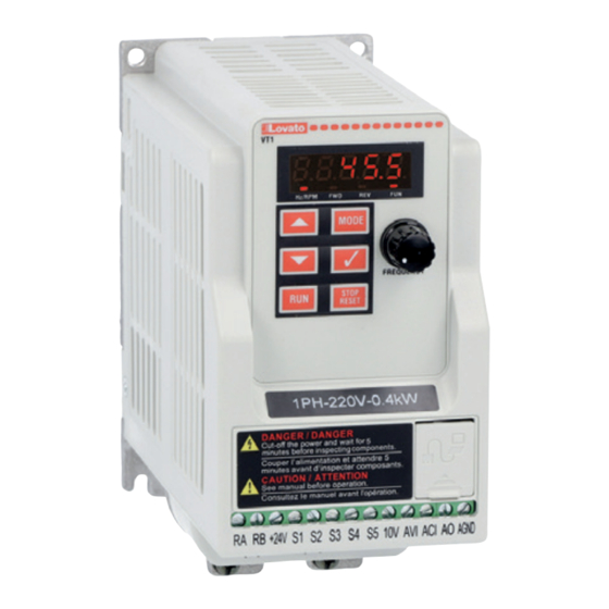
GB VARIABLE SPEED DRIVES
GB
Instruction manual
VT1...
ATTENZIONE!
– Leggere attentamente il manuale prima dell'utilizzo e l'installazione.
– Questi apparecchi devono essere installati da personale qualificato, nel rispetto delle vigenti normative
impiantistiche, allo scopo di evitare danni a persone o cose.
– Prima di qualsiasi intervento sullo strumento, togliere tensione dagli ingressi di misura e di alimentazione e
cortocircuitare i trasformatori di corrente.
– Il costruttore non si assume responsabilità in merito alla sicurezza elettrica in caso di utilizzo improprio del dispositivo.
– I prodotti descritti in questo documento sono suscettibili in qualsiasi momento di evoluzioni o di modifiche. Le
descrizioni ed i dati a catalogo non possono pertanto avere alcun valore contrattuale.
– Un interruttore o disgiuntore va compreso nell'impianto elettrico dell'edificio. Esso deve trovarsi in stretta vicinanza
dell'apparecchio ed essere facilmente raggiungibile da parte dell'operatore. Deve essere marchiato come il dispositivo di
interruzione dell'apparecchio: IEC/ EN 61010-1 § 6.11.3.1.
– Pulire l'apparecchio con panno morbido, non usare prodotti abrasivi, detergenti liquidi o solventi.
UWAGA!
– Przed u yciem i instalacją urządzenia nale y uwa nie przeczytać niniejszą instrukcję.
– W celu uniknięcia obra eń osób lub uszkodzenia mienia tego typu urządzenia muszą być instalowane przez
wykwalifikowany personel, zgodnie z obowiązującymi przepisami.
– Przed rozpoczęciem jakichkolwiek prac na urządzeniu nale y odłączyć napięcie od wejść pomiarowych i zasilania oraz zewrzeć
zaciski przekładnika prądowego.
– Producent nie przyjmuje na siebie odpowiedzialności za bezpieczeństwo elektryczne w przypadku niewłaściwego u ytkowania
urządzenia.
– Produkty opisane w niniejszym dokumencie mogą być w ka dej chwili udoskonalone lub zmodyfikowane. Opisy oraz dane
katalogowe nie mogą mieć w związku z tym adnej wartości umownej.
– W instalacji elektrycznej budynku nale y uwzględnić przełącznik lub wyłącznik automatyczny. Powinien on znajdować się w
bliskim sąsiedztwie urządzenia i być łatwo osiągalny przez operatora. Musi być oznaczony jako urządzenie słu ące do wyłączania
urządzenia: IEC/ EN 61010-1 § 6.11.3.1.
– Urządzenie nale y czyścić miękką szmatką, nie stosować środkow ściernych, płynnych detergentow lub rozpuszczalnikow.
ПРЕДУПРЕЖДЕНИЕ!
– Прежде чем приступать к монтажу или эксплуатации устройства, внимательно ознакомьтесь с одержанием
настоящего руководства.
– Во избежание травм или материального ущерба монтаж должен существляться только квалифицированным персоналом
в соответствии с действующими нормативами.
– Перед проведением любых работ по техническому обслуживанию устройства необходимо обесточить все измерительные
и питающие входные контакты, а также замкнуть накоротко входные контакты трансформатора тока (ТТ).
– Производитель не несет ответственность за обеспечение электробезопасности в случае ненадлежащего использования
устройства.
– Изделия, описанные в настоящем документе, в любой момент могут подвергнуться изменениям или
усовершенствованиям. Поэтому каталожные данные и описания не могут рассматриваться как действительные с точки
зрения контрактов
– Электрическая сеть здания должна быть оснащена автоматическим выключателем, который должен быть расположен
вблизи оборудования в пределах доступа оператора. Автоматический выключатель должен быть промаркирован как
отключающее устройство оборудования: IEC /EN 61010-1 § 6.11.3.1.
– Очистку устройства производить с помощью мягкой сухой ткани, без применения абразивных материалов, жидких
моющих средств или растворителей.
D KKAT!
– Montaj ve kullanımdan önce bu el kitabını dikkatlice okuyunuz.
– Bu aparatlar kişilere veya nesnelere zarar verme ihtimaline karşı yürürlükte olan sistem kurma normlarına göre
kalifiye personel tarafından monte edilmelidirler
– Aparata (cihaz) herhangi bir müdahalede bulunmadan önce ölçüm girişlerindeki gerilimi kesip akım transformatörlerinede kısa
devre yaptırınız.
y p
– Üretici aparatın hatalı kullanımından kaynaklanan elektriksel güvenliğe ait sorumluluk kabul etmez.
– Bu dokümanda tarif edilen ürünler her an evrimlere veya değişimlere açıktır. Bu sebeple katalogdaki tarif ve değerler herhangi bir
bağlayıcı değeri haiz değildir.
– Binanın elektrik sisteminde bir anahtar veya şalter bulunmalıdır. Bu anahtar veya şalter operatörün kolaylıkla ulaşabileceği yakın
bir yerde olmalıdır. Aparatı (cihaz) devreden çıkartma görevi yapan bu anahtar veya şalterin markası: IEC/ EN 61010-1 § 6.11.3.1.
– Aparatı (cihaz) sıvı deterjan veya solvent kullanarak yumuşak bir bez ile siliniz aşındırıcı temizlik ürünleri kullanmayınız.
măsurare
G
B
1
Advertisement
Table of Contents
Troubleshooting

Related Manuals for LOVATO ELECTRIC VT1 Series


Summary of Contents for LOVATO ELECTRIC VT1 Series
- Page 1 GB VARIABLE SPEED DRIVES Instruction manual LOVATO ELECTRIC S.P.A. 24020 GORLE (BERGAMO) ITALIA VIA DON E. MAZZA, 12 TEL. 035 4282111 E-mail info@ ovato lectric.com www. ovato lectric.com VT1... WARNING! ATTENZIONE! – Carefully read the manual before the installation or use.
-
Page 2: Table Of Contents
CONTENTS SAFETY PRECAUTIONS ......................................BEFORE POWER UP ..................................................DURING POWER UP ..................................................BEFORE OPERATION..................................................DURING OPERATION ..................................................DRIVE DISPOSAL ..................................................ENVIRONMENT AND INSTALLATION .................................... 2.1 ENVIRONMENT ...................................................... PRODUCT OVERVIEW AND SPECIFICATIONS ..........................................2.2.1 PRODUCT OVERVIEW ..............................................2.2.2 PRODUCT SPECIFICATIONS ............................................2.2.3 GENERAL SPECIFICATIONS ............................................ -
Page 3: Safety Precautions
1 SAFETY PRECAUTIONS 1.1 BEFORE POWER UP DANGER! Make sure the main circuit connections are correct. Single phase L1(L) and L3(N) are power-input terminals and must not be mistaken for T1,T2 and T3. Otherwise, drive damage can result. CAUTION! The line voltage applied must comply with the drive’s specified input voltage (see the nameplate). To avoid the front cover from disengaging, or other damage do not carry the drive by its covers. -
Page 4: Environment And Installation
2 ENVIRONMENT AND INSTALLATION 2.1 ENVIRONMENT Installation environment has a direct effect on the correct operation and the life expectancy of the drive. Install the drive in an environment complying with the following conditions. Protection Protection class IP20 Open type Suitable environment Operating temperature -10~40°C for size 1 (0.2-0.4-0.75kW, models without built-in fan), -10~50°C for size 2 (1.5-2.2kW, models with built-in fan) -
Page 5: General Specifications
2.2.3 GENERAL SPECIFICATIONS Item VT1 drive Control Mode V/F Control + SLV control Frequency Range 0.01~599.00Hz Speed accuracy (100% torque) V/F: 3% SLV: 1% Starting Torque V/F: 3Hz / 100% SLV: 3Hz / 150% Setting resolution Digital input : 0.01Hz Analog input : 0.015Hz/60Hz Keypad : Set directly with L M keys or the potentiometer on the keypad Frequency Setting... -
Page 6: Installation
2.3 INSTALLATION 2.3.1 MOUNTING ON A FLAT SURFACE Size 1 Size 2 Screw: M4 2.3.2 INSTALLATION SPACE Provide sufficient air circulation space for cooling as shown in examples below. Install the drive on surfaces that provide good heat dissipation. SINGLE UNIT INSTALLATION SIDE-BY-SIDE INSTALLATION Install the drive verticality to obtain effective cooling Control... -
Page 7: Wiring Guidelines
2.4 WIRING GUIDELINES 2.4.1 MAIN CONSIDERATIONS 1 Tightening torque for screw terminals: refer to the table below, when using a screwdriver or any other suitable tools to make connections. 2 Power terminals for single phase supply: L1 (L), L3 (N) 3 For all cabling use copper wires and the cable size shall be according to the table below rated at 105°C. -
Page 8: Wiring And Emc Guidelines
2.4.4 WIRING AND EMC GUIDELINES For effective interference suppression, do not route power and control cables in the same conduit or trunking. To prevent radiated noise, motor cable should be put in a metal conduit. Alternatively an armored or shielded type motor cable should be used. For effective suppression of noise emissions the cable armor or shield must be grounded at both ends to the motor and the drive ground. -
Page 9: Considerations For Peripheral Equipment
2.5 CONSIDERATIONS FOR PERIPHERAL EQUIPMENT POWER SUPPLY ~ ~ ~ Power Supply Make sure the correct voltage is applied to avoid damaging the drive. MOLDED-CASE CIRCUIT BREAKER (MCCB) AND RCD Molded Use a molded-case circuit breaker (MCCB) that conforms to the rated voltage and current of the drive. Circuit Do not use the circuit breaker as the run/stop switch for the drive. -
Page 10: Wiring Diagrams
2.7.1 STANDARD WIRING Magnetic Thermal Contactor relay MCCB L1 L Power Inverter Induction source output Motor input Thermal L3 N relay ON-OFF Ground 1:Data+ Surge 2:Data- Suppressor Pin 1 to Pin 8 3:Data+ CON2 FWD (Run/Stop) 4:Reserved 5:Reserved RS485 REV (Run/Stop) Note: Multifunction 6:Data-... -
Page 11: Multi Pump Wiring Diagrams
2.7.3 MULTI PUMP WIRING DIAGRAMS 2.7.3.1 PUMP WIRING DIAGRAM FOR PRESSURE SENSOR OF CURRENT TYPE SINGLE PUMP OPERATION MULTI-PUMP OPERATION... -
Page 12: Pump Wiring Diagram For Pressure Sensor Of Voltage Type
2.7.3.2 PUMP WIRING DIAGRAM FOR PRESSURE SENSOR OF VOLTAGE TYPE SINGLE PUMP OPERATION MULTI-PUMP OPERATION Notes: 1. It is required to reconnect after setting Master and Slave. 2. When the communication modes is selected to be multiple pumps in parallel connection, the baud rate setting 09-02 of Master and Slave are required to be consistent. Refer to parameter 14-31 for the actions in parallel connection modes. -
Page 13: Terminal Description
2.8 TERMINAL DESCRIPTION 2.8.1 DESCRIPTION OF MAIN CIRCUIT TERMINALS L1(L) L3(N) Terminal symbols Function description L1(L) Main power input, single phase: L1(L) / L3(N) L3(N) Drive output, connect to U, V, W terminals of motor Ground terminal 2.8.2 DESCRIPTION OF CONTROL CIRCUIT TERMINALS Terminal symbols Function description Signal level... -
Page 14: Programming
3 PROGRAMMING 3.1 KEYPAD DESCRIPTION 3.1.1 OPERATOR PANEL FUNCTIONS Type Item Function Digital display and LEDs Main digital displays Frequency, parameters, voltage, current, temperature, fault messages. LED Status – Hz/RPM: ON when the frequency or line speed is displayed.OFF when the parameters are displayed. –... - Page 15 LED display examples Display Description In stop mode shows the set frequency In run mode shows the actual output frequency Selected parameter Parameter value Output voltage Output current in Amps DC Bus voltage Temperature PID feedback value Error display Analogue Current / Voltage ACID / AVI . Range ( 0~1000) LED Status description LED Indicator light Status Frequency / line...
-
Page 16: Digital Display Setup
3.1.3 DIGITAL DISPLAY SETUP On power up digital display screens will be as shown below. MODE MODE 2sec later Parameter Power supply Frequency User selectable display formats: 12- 00 Display Mode Range 0 0 0 High Each of the above 5 digits can be set to any of the selections below from 0 to 7 0 :Disable display 1 :Output Current 2 :Output Voltage... -
Page 17: Example Of Keypad Operation
Increment/ Decrement key functions: 1. “L”/ “M” : Short time press Long time press Quick pressing of these keys will increment or decrement the selected digit by one. Extended pressing will increment or decrement the selected digit continuously. 2. “</ENT” Key functions : “</ENT”... - Page 18 Example2: Modifying the frequency from keypad in run and stop modes. Modify frequency is stopping Modify frequency is stopping Power supply Power supply 2sec later 2sec later Set frequency display Set frequency display Press run Short press </ENT once Actual display Short press </ENT once Modify bit <unit>...
-
Page 19: Operation Control
3.1.5 OPERATION CONTROL Stop Stop Actual output frequency Stop Power 3.2 PARAMETER GROUPS Parameter group No. Description Group 00 Basic parameters Group 01 V/F pattern selections and setup Group 02 Motor parameters Group 03 Multi function digital Inputs/Outputs Group 04 Analog inputs/ Analog output functions Group 05 Preset frequency Selections... - Page 20 Group 00 - Basic parameters Description Range Factory Setting Note 00-00 Control mode 0: V/F mode 1: SLV mode (sensorless vector) 00-01 Motor rotation 0: Forward 1: Reverse 00-02 Main run source selection 0: Keypad 1: External run/stop control 2: Communication 00-03 Alternative run source selection 0: Keypad...
- Page 21 Group 02 - Motor parameters Description Range Factory Setting Note 02-00 Motor no load current ---- A by motor nameplate 02-01 Motor rated current (OL1) ---- A by motor nameplate 02-02 V/F slip compensation 0.0 ~ 100.0 % 02-03 Motor rated speed ---- rpm by motor nameplate 02-04...
- Page 22 Group 03- Multi function digital Inputs/Outputs Description Range Factory Setting Note 03-13 Output frequency detection level 0.00~599.00 Hz 0.00 03-14 Frequency detection band 0.00~30.00 Hz 2.00 03-15 Output current detection level 0.1~999.9 A 03-16 Output current detection period 0.1~10.0 sec 03-17 External brake release level 0.00~20.00 Hz...
- Page 23 Group 05- Preset frequency selections Description Range Factory Setting Note 05-17 Preset speed 0 – Acc time 0.1 ~ 3600.0 sec 10.0 05-18 Preset speed 0 – Dec time 10.0 05-19 Preset speed 1 – Acc time 10.0 05-20 Preset speed 1 – Dec time 10.0 05-21 Preset speed 2 –...
- Page 24 Group 07- Start/Stop command setup Description Range Factory Setting Note 07-00 Restart after momentary power loss 0: Disabled 1: Enabled 07-01 Auto restart delay time 0.0~6000.0 sec 07-02 Number of auto restart attempts 0~10 07-03 Reset mode setting 0: Enable reset only when run command is Off 1: Enable reset when run command is On or Off 07-04 Direct running after power up...
- Page 25 Group 09- Communication function setup Description Range Factory Setting Note 09-00 Assigned communication station number 1 ~ 32 *2*3 09-01 Communication protocol 0: Modbus RTU *2*3 1: Modbus ASCII 2: BACnet 09-02 Baud rate setting (bps) 0 :4800 *2*3 1: 9600 2: 19200 3: 38400 4: Remote control is enabled...
- Page 26 Group 11- Performance control functions Description Range Factory Setting Note 11-00 Reverse operation control 0: Reverse command is enabled 1: Reverse command is disabled 11-01 Carrier frequency 1~16 kHz 11-02 Carrier mode selection 0: Mode 0, 3phase PWM modulation 1: Mode 1, 2phase PWM modulation 2: Mode 2, 2phase soft PWM modulation 11-03 Carrier frequency reduction by temperature rise...
- Page 27 Group 13 - Inspection and maintenance functions Description Range Factory Setting Note 13-00 Drive horse power code ---- 13-01 Software version ---- *3*4 13-02 Fault log (last 3 faults) ---- *3*4 13-03 Accumulated operation time 1 0~23 hours 13-04 Accumulated operation Time 2 0~65535 days ---- 13-05...
-
Page 28: Parameter Function Description
Group 14- Pump application function Description Range Factory Setting Note 14-35 Selection of multiple pumps shift operation 0: No function 1: Timer alternately selection 2: Sleep stop alternately selection 3: Timer and sleep stop alternately selection 4: Multiple pumps test mode 14-37 Leakage detection time 0.0~100.0... - Page 29 Two external switches are required, one for forward direction and the other for reverse. Switch type: two position, maintained type. (This is two wire mode). 1. Forward (Run/Stop) Switch Select one of the multifunction inputs [S1 to S5] and set the relevant parameter 03-00 to 03-04 = 0 (Forward run /Stop mode.) 2.
- Page 30 00-05 Main Frequency Command Source Selection 00-06 Alternative Frequency Command Source Selection Range 0 :UP/DOWN of Keypad 1 :Potentiometer on Keypad 2 :External AVI Analog Signal Input 3 :External ACI Analog Signal Input 4 :External Up/Down Frequency Control 5 :Communication setting Frequency 6 :PID Output frequency –...
- Page 31 00-14 Acceleration time 1 Range 0.1~3600.0 s 00-15 Deceleration time 1 Range 0.1~3600.0 s 00-16 Acceleration time 2 Range 0.1~3600.0 s 00-17 Deceleration time 2 Range 0.1~3600.0 s – Preset Acceleration and Deceleration times by above parameters are the time taken for the output frequency to ramp up or ramp down between the upper and the lower V/F frequency limits. –...
- Page 32 GROUP 01 - V/F PATTERN SELECTIONS AND SETUP 01-00 Volts/Hz Patterns (V/F) Range – Set 01-00 to one of the following preset V/f selections 1~6 according to the required application. – Parameters 01-02~01-09 can not be modified (read only). – Six fixed V/f patterns are shown below. 1~3 for 50 Hz systems and 4~6 for 60 Hz. –...
- Page 33 01-01 V/f Maximum voltage Range 170.0~264.0 V 01-02 Maximum Frequency (base frequency) Range 0.2~ 599.00 Hz 01-03 Maximum Frequency Voltage Ratio Range 0.0 ~ 100.0 % 01-04 Medium Frequency 2 Range 0.1~599.00 Hz 01-05 Medium Frequency Voltage Ratio 2 Range 0.0 ~ 100.0 % 01-06 Medium Frequency 1...
- Page 34 01-13 Motor Hunting Prevention Coefficient Range 1~8192 01-14 Motor Hunting Prevention Gain Range 0~100 % 01-15 Motor Hunting Prevention Limit Range 0.0~100.0 % – In the situation of no power and no-load that damping is low, active and reactive energy fluctuations will greatly stimulate the drive output current oscillations. Appropriately adjusting 01-12 can suppress oscillation by compensating V/F voltage command.
- Page 35 02-04 Motor Rated Voltage Range ---- – In order to prevent the output voltage of drive is too high. The output voltage value will not be higher than 02-04. 02-04 can be changed during operation. Note: Please set the value according to motor’s nameplate. 02-05 Motor Rated Power Range...
- Page 36 02-18 SLV With Load Torque Compensation Gain Range 0~200 % – Please refer the contents as parameter 02-13 / 02-14. 02-19 SLV Slip Compensation Select Range 0: Slip Compensation Select 1 1: Slip Compensation Select 2 – When output current lower or equal to 02-00(no load), the value of slip compensation will be equal to (02-13)*(02-16)(slip compensation select 1) –...
- Page 37 C. 3-wire method. Example: Two separate push buttons for RUN and STOP and a two position switch for FWD/REV Set 00-04=2 (3 wire control mode), then terminals S1, S2 and S3 are dedicated to this function and preset selections for parameters 03-00, 03-01 and 03-02.are not relevant. 2) Parameters 03-00~03-04= 4, 3, 2 Preset speed selections.
- Page 38 9) 03-00~03-04= 14 Rapid Stop (controlled deceleration stop) When DI is on, keypad shows “E.S”, motor decelerates to stop according to the setting value of 00-17. When turning off DI (remove ES), VT1 stays in “stop” status. VT1 runs again after giving Run command.
- Page 39 03-07 Up/Down keep Frequency status after a stop command Range After a stop command in Up/Down mode: 0 : The preset frequency is held as the drive stops. 1 : The preset frequency is reset to 0 Hz as the drive stops. 2 : The preset frequency is held as the drive stops, the function remains enabled.
- Page 40 4) 03-11= 3 RY1 will be ON when Setting Freq. and Output Frequency reached (03-13 ± 03-14). When Frequency Detection Range Lower Limit <Setting Freq. <Frequency Detection Range Upper Limit And, Frequency Detection Range Lower Limit <Output Freq. <Frequency Detection Range Upper Limit, Relay output will be ON (Allowable tolerance ±0.01) Example: Frequency Detection Level (03-13) =30, and Frequency Detection Width (03-14) =5 cause frequency detection range upper limit = 35, and Frequency Detection Range lower limit = 25.
- Page 41 03-15 Output Current Detection Level Range 0.1~999.9 A 03-16 Output Current Detection Period Range 0.1~10.0 Sec – 03-11= 13 , RY1 will be on as soon as the output current value > output current detection level (03-15). – 03-15: Setting range (0.1~15.0 Amps) as required according to the rated motor current. –...
- Page 42 GROUP 04 - ANALOG INPUTS/ ANALOG OUTPUT FUNCTIONS 04-00 Analog Voltage and Current input selections Range 0 :0~10V 0~20mA 1 :0~10V 4~20mA 2 :2~10V 0~20mA 3 :2~10V 4~20mA – Analog Input Scaling formulas: AVI(0~10V), ACI(0~20mA) V(v) AVI(0~10V):F(Hz) = AVI(0~10V):F(Hz) = ) ( ) X(00-12) –––—...
- Page 43 Figure 3 Figure 4 (2) Offset bias set to 0% (04-03) and effect of modifying Analog Gain ( 04-02), Bias type ( 04-04) and slope type( 04-05) are shown in shown Fig 5 and 6. Figure 5 Figure 6 (3) Various other examples of analog input scaling and modification are shown in following figures 7,8,9 and 10. Figure 7 Figure 8 Figure 9...
- Page 44 04-11 Analog Output (AO) function selection. Range 0 :Output frequency 1 :Frequency Setting 2 :Output voltage 3 :DC Bus Voltage 4 :Output current Example: Set 04-11 required according to the following table. 04-12 AO Gain Range 0 ~ 1000 % 04-13 AO Bias Range...
- Page 45 GROUP 05 - PRESET FREQUENCIES SELECTION 05-00 Preset Speed Control mode Selection Range 0 :Common Acceleration / Deceleration. 1 : Individual Acceleration / Deceleration for each preset speed 0-7. 05-01 Preset Speed 0 (Keypad Frequency) 05-02 Preset Speed 1 05-03 Preset Speed 2 05-04 Preset Speed 3...
- Page 46 Mode 1 Example 00-02= 1 (External Run/Stop Control). 00-04= 1 (Operation Mode Run/stop-forward/reverse). S1: 03-00= 0 (RUN/STOP ); S2: 03-01= 1 (Forward/Reverse); S3: 03-02= 2 (Preset speed 1); S4: 03-03= 3 (Preset speed 2); S5: 03-04= 4 (Preset speed 4); When the run command is On/Off, acceleration and deceleration times for each cycle can be calculated as below: time unit is in seconds.
- Page 47 GROUP 06 - AUTO RUN (SEQUENCER) FUNCTION 06-00 Auto Run (sequencer) mode selection Range 0 :Disabled 1 :Single cycle, continues to run from the unfinished step if restarted. 2 :Periodic cycle, continues to run from the unfinished step if restarted. 3 :Single cycle, then holds the speed of final step to run.
- Page 48 Auto RUN (Auto Sequencer) examples are shown in the following pages. Example 1. Single Cycle (06-00=1,4) The drive will run for a single full cycle based on the specified number of sequences, then it will stop. In this example 4 sequences are set, three in forward direction and one in Reverse. Auto Run Mode 06-00=1 or 4 Frequency...
- Page 49 Example 4 and 5 . Auto Run Mode 06-00=1~3, after a restart continues to run from the unfinished step. Auto Run Mode 06-00=4~6, after a restart, it will begin a new cycle. – ACC/DEC time in Auto run mode will be according to the setting of 00-14 / 00-15 or 00-16 / 00-17. –...
- Page 50 07-07 DC Injection Brake Level (%) Range 0~ 20 % Based on the 20% of maximum output voltage – Please refer the formula below. In V/F mode, the value is equal to 0~20% of max output voltage (01-01) In SLV mode, the value is equal to 0~20% of max output voltage (02-04). 07-08 DC Injection Brake Time (Sec) Range...
- Page 51 GROUP 08 - DRIVE AND MOTOR PROTECTION FUNCTIONS 08-00 Trip Prevention Selection Range xxxx0 :Enable Trip Prevention during Acceleration xxxx1 :Disable Trip Prevention during Acceleration xxx0x :Enable Trip Prevention during Deceleration xxx1x :Disable Trip Prevention during Deceleration xx0xx :Enable Trip Prevention in Run Mode xx1xx :Disable Trip Prevention in Run Mode x0xxx :Enable over voltage Prevention in Run Mode x1xxx :Disable over voltage Prevention in Run Mode...
- Page 52 08-07 OH overheat Protection Range 0 :Auto (depends on heat sink temperature) 1 :Operate while in RUN mode 2 :Always Run 3 :Disabled – 08-07=0 : Cooling fan runs as the drive detects temperature rise. Available only on VT1 size 2. –...
- Page 53 5) For different specifications of PTC thermistor, set the values for parameters 08-13 and 08-14 by calculating from the formula shown below. (a) PTC Thermistor Characteristics 08-16 Fan Control Temperature Level Range 10.0~50.0 °C – When 08-07=0 (heat sink temperature detection control for cooling fan). Fan will run when temperature of heat sink is higher than 08-16. When temperature of heat sink decreases below setting value of 08-16 minus 20°C, fan will stop.
- Page 54 When 08-19=0: When 08-19=1: When 08-19=2: Motor overload curves (for general motor)
- Page 55 GROUP 09 - COMMUNICATION FUNCTION SETUP 09-00 Assigned communication station number Range 1 ~ 32 – 09-00 sets the communication station number when there are more than one unit on the communication network. Up to 32 slave units can be controlled from one master controller such as a PLC.
- Page 56 GROUP 10 - PID FUNCTION SETUP PID block diagram 10-00 PID target value selection Range 0 :Potentiometer on Keypad 1 :External AVI Analog Signal Input 2 :External ACI Analog Signal Input 3 :Target Frequency set by Communication method 4 :Set from keypad by parameter 10-02 5 :Set from preset frequency –...
- Page 57 10-04 Feedback Gain coefficient Range 0.00 ~ 10.00 – 10-04 is the calibration gain. Deviation = set point – (feedback signal×10-04). 10-05 Proportional Gain Range 0.0 ~ 10.0 – 10-05: Proportion gain for P control. 10-06 Integral Time Range 0.0 ~ 100.0 s –...
- Page 58 10-17 PID Sleep Frequency Level Range 0.00~599.00 Hz 10-18 PID Sleep Function Delay Time Range 0.0 ~25.5 s 10-19 PID Wake up frequency Level Range 0.00 ~ 599.00 Hz 10-20 PID Wake up function Delay Time Range 0.0 ~ 25.5 s –...
- Page 59 11-02 Carrier mode selection Range 0 :Carrier mode0 3-phase PWM modulation 1 :Carrier mode1 2-phase PWM modulation 2 :Carrier mode2 Random PWM modulation The function can be used for audible noise reduction from a motor. It can be used in cases where the 100% torque from motor is not critical but it is necessary to reduce the audible noise. –...
- Page 60 11-08 Skip frequency 1 11-09 Skip frequency 2 11-10 Skip frequency 3 Range 0.00 ~ 599.00 Hz 11-11 Skip frequency range. (± frequency band) Range 0.00 ~ 30.00 Hz Skip frequency parameters can be used to avoid mechanical resonance in certain applications. Example: 11-08=10.00(Hz);...
- Page 61 11-14 Regeneration Prevention Voltage Level Range 300.0~400.0 V – If the DC bus voltage level is set too low, then over-voltage protection will not be reached, but the actual deceleration time will be extended. 11-15 Regeneration Prevention Frequency Limit Range 0.00~15.00 Hz –...
- Page 62 12-04 Custom Units (Line Speed) Display Mode Range 0 :Drive Output Frequency is Displayed 1 :Line Speed is Displayed in Integer (xxxxx) 2 :Line Speed is Displayed with One Decimal Place (xxxx.x) 3 :Line Speed is Displayed with Two Decimal Places (xxx.xx) 4 :Line Speed is Displayed with Three Decimal Places (xx.xxx) –...
- Page 63 13-03 Accumulated Drive Operation Time 1 Range 0~23 Hours 13-04 Accumulated Drive Operation Time 2 Range 0~65535 Days 13-05 Accumulated Drive Operation Time Mode Range 0 :Power on time 1 :Operation time – When the operation time recorded in accumulator 1 (parameter 13-03) reaches 24 hours the recorded value in accumulator 2 parameter 13-04 changes to 1 day and the value in accumulator 1 is reset to 0000.
- Page 64 GROUP 14 – PUMP APPLICATION FUNCTION 14-00 Function selection Range 0: Disable 1: Pump application – Select function of pump via parameter 14-00. This function is enabled if PID control mode (10-03) is enabled. – When 14-00=1 and 10-03=1 (PID function is enabled), pump function will be enabled. 14-01 Setting of single and multiple pumps and master and slave machines Range...
- Page 65 Increase Setting Value Decrease Setting Value Main Feature Proportional (Pros) Increase response time (Pros) Reduce jittering Increase stabilized Gain (P) (Cons) Might cause pump jittering (Cons) Slow down response time Integral (Pros) Smooth output frequency (Pros) Fast response For smooth feedback Time (I) (Cons) Slow down response (Cons) Change rapidly output frequency...
- Page 66 14-14 Stop time of high pressure Range 0.0~600.0 s – When the warning signal of high pressure occurs and pressure feedback value is higher than maximum pressure limit, stop time of high pressure starts to count. If pressure feedback value is lower than maximum pressure limit during counting time, the stop time will recount and the drive will display stop error signal of OPbFt when the stop time ends.
- Page 67 14-18 Time of loss pressure detection Range 0.0~600.0 s 14-19 Proportion of loss pressure detection Range 0~100 % – When 14-19=0, function of loss pressure detection is disabled. – When 14-19 > 0, If the feedback pressure value is lower than the value of (14-02) x (14-19) and the detection time of loss pressure (14-18) passes, the drive jumps to fault signal (FBLSS). 14-20 Switching of pressure and percentage Range...
- Page 68 Diagram for download detection of water pressure – When 14-25=0.0 (sec) means to disable the function of water pressure detection. – When function of water pressure detection is enabled, it can shorten the time of jumping into sleep without water consumption or with mild water consumption. –...
- Page 69 Note: 1. When Master modifies the pressure setting, it requires pressing ENTER key to modify the pressure setting of Slave. 2. When the switching time of multiple pumps in parallel (14-29) changes and reconnection, it will recount the time. Dual pumps start up process A.
- Page 70 14-34 Tolerance range of constant pressure 2 Range When 14-20=0, range is 0.00~650.00 When 14-20=1, range is 0~100 14-35 Selection of multiple pumps shift operation Range 0: No function 1: Timer alternately selection 2: Sleep stop alternately selection 3: Timer and sleep stop alternately selection 4: Multiple pumps test mode –...
- Page 71 Leakage detection case 2: Pressure tolerance lower than 14-38 – When 14-37=0.0 (sec), switch off this function. – When pump is at shutdown state, pressure will drop over time if pipeline leaks. Drive will keep sleep state if pressure variation is lower than the value of parameter 14-38 in every detection time (14-37) and pump will restart if pressure variation is larger than that of 14-38 or pressure tolerance range is over the value of parameter 14-39 in the detection time.
-
Page 72: Troubleshooting And Maintenance
4 TROUBLESHOOTING AND MAINTENANCE 4.1 ERROR DISPLAY AND CORRECTIVE ACTION 4.1.1 MANUAL RESET AND AUTO-RESET Faults which cannot be recovered manually Display Content Cause Corrective action -OV- Voltage too high when stopped Detection circuit malfunction Consult with the supplier – OU – -LV- Voltage too low when stopped –... -
Page 73: Keypad Operation Error Instruction
Faults which can be recovered manually but not automatically Display Content Cause Corrective action Over-current during stop Detection circuit malfunction Consult with the supplier Motor overload Loading too large Consider increasing the motor capacity OL 1 Drive overload Excessive Load Consider increasing the drive capacity OL 2 Drive over current:... -
Page 74: Special Conditions
4.1.3 SPECIAL CONDITIONS Display Fault Description StP0 Zero speed at stop In V/f mode, STP0 comes out at less than 1.3Hz (50Hz set) or at less than 1.5Hz (60Hz set) In SLV mode, STP0 comes out at less than 1Hz. StPO StP1 Fail to start directly... -
Page 75: Troubleshooting Of The Drive
4.3 TROUBLESHOOTING OF THE DRIVE 4.3.1 QUICK TROUBLESHOOTING OF THE DRIVE... -
Page 77: Troubleshooting For Oc, Ol Error Displays
4.3.2 TROUBLESHOOTING FOR OC, OL ERROR DISPLAYS... -
Page 78: Troubleshooting For Ov, Lv Error
4.3.3 TROUBLESHOOTING FOR OV, LV ERROR... -
Page 79: The Motor Can Not Run
4.3.4 THE MOTOR CAN NOT RUN... -
Page 80: Motor Overheating
4.3.5 MOTOR OVERHEATING... -
Page 81: Motor Runs Unbalanced
4.3.6 MOTOR RUNS UNBALANCED 4.4 ROUTINE AND PERIODIC INSPECTION To ensure stable and safe operations, check and maintain the drive at regular intervals. Use the checklist below to carry out inspection. Disconnect power after approximately 5 minutes to make sure no voltage is present on the output terminals before any inspection or maintenance. Items Details Checking period... -
Page 82: Peripherals Components
5 PERIPHERALS COMPONENTS 5.1 REACTOR SPECIFICATIONS Drive model Specification Inductance (mH) ‚ Current (A) VT1 02 A240 4.48 VT1 04 A240 3.05 VT1 07 A240 11.0 2.00 VT1 15 A240 15.5 1.42 VT1 22 A240 21.0 1.05 ‚ Calculated inductance based on 3% reactance. 5.2 FUSE SPECIFICATION Drive model Rating... -
Page 83: Appendix - Instructions For Ul
Failure to comply could result in damage to the drive and will void warranty. Lovato Electric is not responsible for any modification of the product made by the user. This product must not be modified. Check all the wiring to ensure that all connections are correct after installing the drive and connecting any other devices. - Page 84 ◆ UL STANDARDS COMPLIANCE This drive is tested in accordance with UL standard UL508C and complies with UL requirements. To ensure continued compliance when using this drive in combination with other equipment, meet the following conditions: INSTALLATION AREA Do not install the drive to an area greater than pollution severity 2 (UL standard). MAIN CIRCUIT TERMINAL WIRING UL approval requires crimp terminals when wiring the drive’s main circuit terminals.
Need help?
Do you have a question about the VT1 Series and is the answer not in the manual?
Questions and answers