Sign In
Upload
Manuals
Brands
LOVATO ELECTRIC Manuals
DC Drives
VLB Series
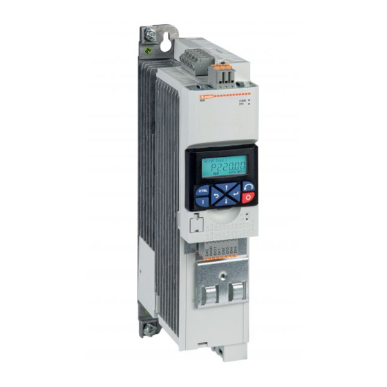
LOVATO ELECTRIC VLB Series Speed Drive Manuals
Manuals and User Guides for LOVATO ELECTRIC VLB Series Speed Drive. We have
2
LOVATO ELECTRIC VLB Series Speed Drive manuals available for free PDF download: Installation Manual
LOVATO ELECTRIC VLB Series Installation Manual (78 pages)
Variable Speed Drives
Brand:
LOVATO ELECTRIC
| Category:
DC Drives
| Size: 2.16 MB
Table of Contents
English
2
Table of Contents
2
1 Safety Information
3
Residual Hazards
3
Intended Use
3
2 Product Description
3
3 Electrical Installation
5
Connection Plan
5
Fuses and Cable Cross-Sections
6
DC-Bus Voltage Operative Range
11
Data of Control Connections
12
Modbus Connection
15
Connection Plan
15
Terminal Data
15
Basic Network Settings
15
Connection of the Safety Module
16
Important Notes
16
Connection Plan
16
Terminal Data
16
4 Commissioning
17
Important Notes
17
Before Initial Switch-On
17
Initial Switch-On / Functional Test
17
5 Quick Guide for Configuration of VLB3 Parameters
18
Navigation in the Menu
18
Reset Parameters to Default
19
Command the Run/Stop of the Motor
20
2-Wires Control from the Flexible I/O Terminal Block
20
From Keypad
20
3-Wires Control from Flexible I/O Terminal Block
20
Frequency Adjustment
21
From Keypad
21
From External Potentiometer
21
From Analog Input Signal Type 0-10V
21
From Analog Input Signal Type 4-20Ma
22
With Preset Frequency Setpoints
22
From Motor Potentiometer (MOP)
23
With Modbus Communication Protocol
23
PID Control - Setpoint Adjusted with Keypad and Feedback Signal Type 0-10V
23
PID Control - Setpoint Adjusted with Keypad and Feedback Signal Type 4-20Ma
23
Motor Parameters
24
Additional Functions
25
Configuration of the Relay Output Function
25
Configuration of the DO1 Digital Output Function
25
Configuration of the AO1 Analog Output Function
26
Enable of the Start at Power-Up Function (Auto-Restart)
26
Command of Digital Inputs from PLC
27
Configuration of the Automatic (PID) / Manual (Frequency Regulation) Mode
27
Control of the Variable Speed Drive by EXCRDU1 Remote Keypad
29
Common Error Codes
30
6 Technical Data
31
Standards and Operating Conditions
31
Rated Data
32
Italiano
38
1 Informazioni Sulla Sicurezza
39
Pericoli
39
Destinazione D'uso
39
2 Descrizione Prodotto
39
3 Installazione Elettrica
41
Layout Connessioni
41
Fusibili E Sezione Cavi
42
Tensione Operativa del Bus-DC
47
Dati Dei Terminali DI Controllo
48
Connessione Modbus
51
Lay-Out Connessioni
51
Terminali
51
Impostazioni Della Rete
51
Connessione Modulo Sicurezza
52
Note Importanti
52
Connessioni
52
Terminali
52
4 Primo Avviamento
53
Note Importanti
53
Prima DI Dare Tensione / Start
53
Accensione Iniziale/Test Funzionali
53
5 Guida Rapida Per la Configurazione Dei Parametri del VLB3
54
Navigazione Tra I Menu
54
Reset Parametri alle Impostazioni DI Fabbrica (Default)
55
Comandi DI Marcia/Arresto del Motore
56
Da Contatto in Morsettiera - Comando a Due Fili
56
Da Tastiera a Bordo Azionamento
56
Da Contatti in Morsettiera - Comando a Tre Fili
56
Regolazione Della Frequenza
57
Da Tastiera a Bordo Azionamento
57
Da Potenziometro Esterno
57
Da Segnale Analogico 0-10V
57
Da Segnale Analogico 4-20Ma
58
Tramite Velocità Preselezionate
58
Da Motopotenziometro (MOP)
59
Tramite Protocollo DI Comunicazione Modbus
59
Funzione PID - Setpoint Impostato da Tastiera a Bordo E Segnale DI Feedback Tipo 0-10V
59
Funzione PID - Setpoint Impostato da Tastiera a Bordo E Segnale DI Feedback Tipo 4-20Ma
59
Parametri Motore
60
Funzioni Aggiuntive
61
Configurazione Della Funzione Dell'uscita a Relè
61
Configurazione Della Funzione Dell'uscita Digitale DO1
61
Configurazione Della Funzione Dell'uscita Analogica AO1
62
Abilitazione Della Funzione DI Start Alla Messa in Tensione (AUTOSTART)
62
Comando Ingressi Digitali da PLC
63
Gestione Funzionamento Modalità Automatica (PID) / Manuale (Regolazione in Frequenza)
63
Controllo Dell'azionamento Tramite Tastiera Remota EXCRDU1
65
Codici DI Errore Comuni
66
6 Dati Tecnici
67
Norme E Condizioni DI Funzionamento
67
Dati Tecnici
68
7 Dimensioni E Installazione Meccanica
74
7 Dimensions and Mechanical Installation
74
Advertisement
LOVATO ELECTRIC VLB Series Installation Manual (70 pages)
VARIABLE SPEED DRIVES
Brand:
LOVATO ELECTRIC
| Category:
DC Drives
| Size: 4.85 MB
Table of Contents
English
2
Table of Contents
2
Electrical Installation
5
Important Notes
5
Protection with Fuses, Circuit Breaker, RCD
5
Connection According to UL
5
Connection Diagram
8
EMC-Compliant Installation
8
Terminal Data
9
DC-Bus Voltage Operative Range
9
Data of Control Terminals
10
Connection of the STO (Safe Torque Off) Safety Module
14
Brake Resistor Connection
15
Commissioning
16
Important Notes
16
Before Initial Switch-On
16
Initial Switch-On / Functional Test
16
Quick Guide for Configuration of VLB3 Parameters
17
Navigation in the Menu
17
Reset Parameters to Default
18
Command the Run/Stop of the Motor
18
2-Wires Control from the Flexible I/O Terminal Block
18
From External Potentiometer
19
Frequency Adjustment
19
3-Wires Control from Flexible I/O Terminal Block
19
From Keypad
19
From Analog Input Signal Type 0-10V
20
From Analog Input Signal Type 4-20Ma
20
With Preset Frequency Setpoints
20
From Motor Potentiometer (MOP)
21
With Modbus Communication Protocol
21
PID Control - Setpoint Adjusted with Keypad and Feedback Signal Type 0-10V
21
PID Control - Setpoint Adjusted with Keypad and Feedback Signal Type 4-20Ma
21
Motor Parameters
22
Configuration of the DO1 Digital Output Function
23
Configuration of the Relay Output Function
23
Additional Functions
23
Configuration of the AO1 Analog Output Function
24
Enable of the Start at Power-Up Function (Auto-Restart)
24
Command of Digital Inputs from PLC
25
Configuration of the Automatic (PID) / Manual (Frequency Regulation) Mode
25
Common Error Codes
27
Technical Data
28
Standards and Operating Conditions
28
Rated Data
29
Ecodesign Directive
33
Italiano
34
Descrizione Prodotto
35
Destinazione D'uso
35
Informazioni Sulla Sicurezza
35
Pericoli
35
Fusibili E Interruttori DI Protezione
37
Installazione Elettrica
37
Note Importanti
37
Connessioni Secondo UL
38
Installazione Elettrica Conforme EMC
40
Schema DI Collegamento
40
Dati Dei Terminali DI Potenza
41
Tensione Operativa del Bus-DC
41
Dati Dei Terminali DI Controllo
42
Comunicazione
44
Comunicazione Modbus-RTU
45
Connessione del Modulo DI Sicurezza STO (Safe Torque Off)
46
Connessione Della Resistenza DI Frenatura
47
Accensione Iniziale/Test Funzionali
48
Note Importanti
48
Prima DI Dare Tensione / Start
48
Primo Avviamento
48
Guida Rapida Per la Configurazione Dei Parametri del VLB3
49
Navigazione Tra I Menu
49
Comandi DI Marcia/Arresto del Motore
50
Da Contatto in Morsettiera - Comando a Due Fili
50
Reset Parametri alle Impostazioni DI Fabbrica (Default)
50
Da Contatti in Morsettiera - Comando a Tre Fili
51
Da Potenziometro Esterno
51
Da Tastiera a Bordo Azionamento
51
Regolazione Della Frequenza
51
Da Segnale Analogico 0-10V
52
Da Segnale Analogico 4-20Ma
52
Tramite Velocità Preselezionate
52
Da Motopotenziometro (MOP)
53
Funzione PID - Setpoint Impostato da Tastiera a Bordo E Segnale DI Feedback Tipo 0-10V
53
Funzione PID - Setpoint Impostato da Tastiera a Bordo E Segnale DI Feedback Tipo 4-20Ma
53
Tramite Protocollo DI Comunicazione Modbus
53
Parametri Motore
54
Configurazione Della Funzione Dell'uscita a Relè
55
Configurazione Della Funzione Dell'uscita Digitale DO1
55
Funzioni Aggiuntive
55
Abilitazione Della Funzione DI Start Alla Messa in Tensione (AUTOSTART)
56
Configurazione Della Funzione Dell'uscita Analogica AO1
56
Comando Ingressi Digitali da PLC
57
Gestione Funzionamento Modalità Automatica (PID) / Manuale (Regolazione in Frequenza)
57
Codici DI Errore Comuni
59
Dati Tecnici
60
Norme E Condizioni DI Funzionamento
60
Dati Tecnici
61
Direttiva Ecodesign
65
Advertisement
Related Products
LOVATO ELECTRIC VLB3 0007 A480
LOVATO ELECTRIC VLB3 0022 A480
LOVATO ELECTRIC VLB3 0055 A480
LOVATO ELECTRIC VLB3 0150 A480
LOVATO ELECTRIC VLB3 0750 A480
LOVATO ELECTRIC VLB30015A480
LOVATO ELECTRIC VLB30150A480
LOVATO ELECTRIC VLB30300A480
LOVATO ELECTRIC VLB3 Series
LOVATO ELECTRIC VLB30022A480XX
LOVATO ELECTRIC Categories
Measuring Instruments
Controller
Control Unit
Multimeter
Relays
More LOVATO ELECTRIC Manuals
Login
Sign In
OR
Sign in with Facebook
Sign in with Google
Upload manual
Upload from disk
Upload from URL