Table of Contents
Advertisement
LOVATO ELECTRIC S.P.A.
24020 GORLE (BERGAMO) ITALIA
VIA DON E. MAZZA, 12
TEL. 035 4282111
FAX (Nazionale): 035 4282200
FAX (International): +39 035 4282400
L
E
E-mail info@
ovato
lectric.com
L
E
Web
www.
ovato
lectric.com
SUMMARY
1. Navigation in the menu ..............................................................................................................................................................................................................................................................................................
2. Reset parameters to default ......................................................................................................................................................................................................................................................................................
3. Command the run/stop of the motor ..........................................................................................................................................................................................................................................................................
3.1 2-wires control from the flexible I/O terminal block ...........................................................................................................................................................................................................................................
3.2 From keypad .......................................................................................................................................................................................................................................................................................................
4. Frequency adjustment ................................................................................................................................................................................................................................................................................................
4.1 From keypad .......................................................................................................................................................................................................................................................................................................
4.2 From external potentiometer ..............................................................................................................................................................................................................................................................................
4.3 From analog input signal type 0-10V .................................................................................................................................................................................................................................................................
4.4 From analog input signal type 4-20mA ..............................................................................................................................................................................................................................................................
4.5 With preset frequency setpoints .........................................................................................................................................................................................................................................................................
4.6 From motor potentiometer (MOP) ......................................................................................................................................................................................................................................................................
4.7 PID Control - Setpoint adjusted with keypad and feedback signal type 0-10V ...................................................................................................................................................................................................
4.8 PID Control - Setpoint adjusted with keypad and feedback signal type 4-20mA ...............................................................................................................................................................................................
5. Motor parameters .......................................................................................................................................................................................................................................................................................................
6. Additional functions ...................................................................................................................................................................................................................................................................................................
6.1 Configuration of the relay output function ..........................................................................................................................................................................................................................................................
6.2 Configuration of the DO1 digital output function ................................................................................................................................................................................................................................................
6.3 Configuration of the AO1 analog output function ...............................................................................................................................................................................................................................................
6.4 Enable of the start at power-up function (auto-restart) ......................................................................................................................................................................................................................................
6.5 Command of digital inputs from PLC .................................................................................................................................................................................................................................................................
6.6 Configuration of the automatic (PID) / manual (frequency regulation) mode ....................................................................................................................................................................................................
6.7 Common error codes .........................................................................................................................................................................................................................................................................................
GB
GB
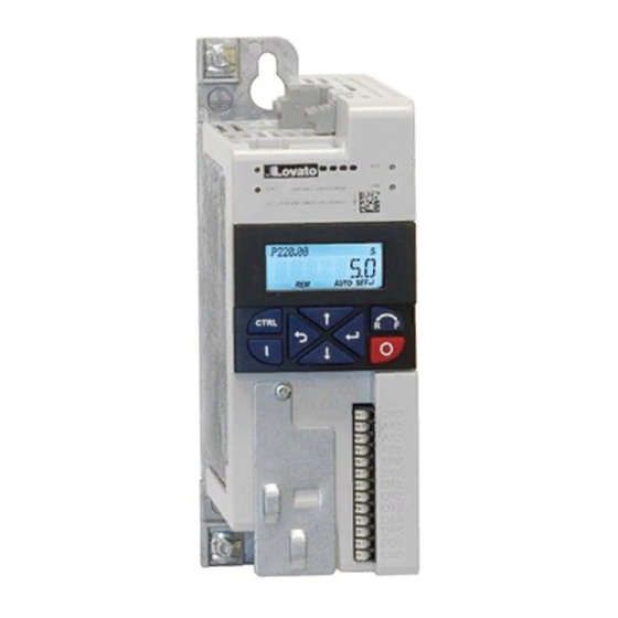
QUICK GUIDE FOR THE CONFIGURATION OF VARIABLE SPEED
DRIVES
VLA1...
Steps to follow for the configuration of the variable speed drive:
LEARN HOW TO NAVIGATE THE MENU
See chapter 1
RESET PARAMETERS TO
DEFAULT
See chapter 2
HOW DO YOU WANT TO COMMAND
THE RUN AND STOP OF THE MOTOR?
See chapter 3
HOW DO YOU WANT TO ADJUST
THE FREQUENCY OF THE MOTOR?
See chapter 4
SET THE MOTOR PARAMETERS
See chapter 5
CONFIGURE ADDITIONAL FUNCTIONS
See chapter 6
PAGE
2
3
4
4
4
5
5
5
5
6
6
7
7
7
8
9
9
9
10
10
11
11
13
1
Advertisement
Table of Contents

Subscribe to Our Youtube Channel
Related Manuals for LOVATO ELECTRIC VLA1 series


Summary of Contents for LOVATO ELECTRIC VLA1 series
-
Page 1: Table Of Contents
QUICK GUIDE FOR THE CONFIGURATION OF VARIABLE SPEED DRIVES LOVATO ELECTRIC S.P.A. 24020 GORLE (BERGAMO) ITALIA VIA DON E. MAZZA, 12 TEL. 035 4282111 FAX (Nazionale): 035 4282200 FAX (International): +39 035 4282400 VLA1… E-mail info@ ovato lectric.com www. ovato lectric.com... -
Page 2: Navigation In The Menu
1. NAVIGATION IN THE MENU AND LOADING DEFAULT SETTINGS Function of the keypad keys Navigate: select group/parameter. Change parameter setting. Pressed shortly: enter in the sub parameter level. Keep pressed for more than 3 sec to save parameter settings in the memory. Exit from the menu/parameter Stop motor Run motor... -
Page 3: Reset Parameters To Default
2. RESET PARAMETERS TO DEFAULT To reset all the parameters to factory settings follow this procedure: – Set the parameter P700.01 = 1 (load default settings) – Press the button several times to exit from the programming menu until it appears the text STOP. –... -
Page 4: Command The Run/Stop Of The Motor
3. COMMAND THE RUN/STOP OF THE MOTOR 3.1 2-wires control from the flexible I/O terminal block Parameter Function Setting Description P400.01 VSD enable VSD always enabled (default setting) P400.02 Run/stop command Run/stop command from digital input DI1 (connected between terminals DI1-24V) 3.2 From keypad Start Stop... -
Page 5: Frequency Adjustment
4. FREQUENCY ADJUSTMENT 4.1 From keypad Increase the frequency Decrease the frequency Parameter Function Setting Description P201.01 Frequency setpoint source Frequency adjusted from keypad P210.00 Minimum frequency Insert the value of the minimum frequency P211.00 Maximum frequency 50Hz Insert the value of the maximum frequency P220.00 Acceleration time 5sec... -
Page 6: From Analog Input Signal Type 4-20Ma
4.4 From analog input signal type 4-20mA Analog signal 4-20mA – 2-wire sensor with output 4-20mA supplied at 24VDC – Parameter Function Setting Description P201.01 Frequency setpoint source Frequency adjusted with analog input 1 (AI1) P210.00 Minimum frequency Insert the value of the minimum frequency P211.00 Maximum frequency 50Hz... -
Page 7: From Motor Potentiometer (Mop)
4.6 From motor potentiometer (MOP) MOP UP MOP DOWN If the motor potentiometer is active as setpoint source, the frequency setpoint can be changed via the triggers assigned to two input contacts configured with the functions "MOP UP" (increase frequency) and "MOP DOWN"... -
Page 8: Motor Parameters
5. MOTOR PARAMETERS Parameter Function Setting Description P208.01 AC input voltage 0 (=230V) Insert the value of the supply voltage P300.00 Motor control mode V/f characteristic control, open loop P302.00 V/f shape Linear V/f (Applications: conveyor belts, …) Quadratic V/f (Applications: pumps, fans, …) P303.01 V/f Base voltage 230V... -
Page 9: Additional Functions
6. ADDITIONAL FUNCTIONS 6.1 Configuration of the relay output function To configure the function of the relay output with changeover contact (terminals NO-COM-NC) is necessary to set the parameter P420.01. Here below are listed the most common functions. Parameter Function Setting Description P420.01... -
Page 10: Configuration Of The Ao1 Analog Output Function
6.3 Configuration of the AO1 analog output function To configure the function of the AO1 analog output (terminals AO1-GND) is necessary to set the following parameters. Parameter Function Setting Description P440.01 AO1 analog output range 0…10VDC 0…5VDC 2…10VDC 4…20mA 0…20mA P440.02 AO1 analog output function Actual output frequency (resolution 0.1 Hz) -
Page 11: Command Of Digital Inputs From Plc
6.5 Command of digital inputs from PLC Connection to PLC with dry contact output Connection to PLC with PNP output Connection to PLC with tensioned output 24VDC 6.6 Configuration of the automatic (PID) / manual (frequency regulation) mode Sensor with output 0...10VDC –... - Page 12 Manual mode (MAN) In MAN mode the PID control is de-activated and the variable speed drive works with manual regulation of the frequency setpoint via a potentiometer connected to the AI2 analog input (type 0-10V). In this example we configure the variable speed drive to provide an output frequency of 0Hz when the potentiometer is at minimum of its regulation scale (0V) and a frequency of 50Hz when the potentiometer is at maximum (10V).
-
Page 13: Common Error Codes
6.8 Common error codes Error code Description Possible causes Remedy 0x2350 Motor overload (i Motor thermally overloaded. Possible causes: – Check drive dimensioning. – Impermissible continuous current. – Check machine/driven mechanics for excessive load. – Too frequent acceleration processes. – Too long acceleration processes. 0x2320 Short circuit/earth leakage –...
Need help?
Do you have a question about the VLA1 series and is the answer not in the manual?
Questions and answers