Table of Contents
Advertisement
Available languages
Available languages
LOV TO ELECTRIC S.P. .
24020 GORLE (BERGAMO) ITALIA
VIA DON E. MAZZA, 12
TEL. 035 4282111
FAX (Nazionale): 035 4282200
FAX (International): +39 035 4282400
L
E
E-mail info@
ovato
lectric.com
L
E
Web
www.
ovato
lectric.com
W RNING!
– Carefully read the manual before the installation or use.
– This equipment is to be installed by qualified personnel, complying to current standards, to avoid
damages or safety hazards.
– Before any maintenance operation on the device, remove all the voltages from measuring and supply inputs and short-
circuit the CT input terminals.
– The manufacturer cannot be held responsible for electrical safety in case of improper use of the equipment.
– Products illustrated herein are subject to alteration and changes without prior notice. Technical data and descriptions in
the documentation are accurate, to the best of our knowledge, but no liabilities for errors, omissions or contingencies
arising there from are accepted.
– A circuit breaker must be included in the electrical installation of the building. It must be installed close by the
equipment and within easy reach of the operator. It must be marked as the disconnecting device of the equipment:
IEC /EN 61010-1 § 6.11.3.1.
– Clean the device with a soft dry cloth; do not use abrasives, liquid detergents or solvents.
TTENTION !
– Lire attentivement le manuel avant toute utilisation et installation.
– Ces appareils doivent être installés par un personnel qualifié, conformément aux normes en vigueur en
matière d'installations, afin d'éviter de causer des dommages à des personnes ou choses.
– Avant toute intervention sur l'instrument, mettre les entrées de mesure et d'alimentation hors tension et court-circuiter
les transformateurs de courant.
– Le constructeur n'assume aucune responsabilité quant à la sécurité électrique en cas d'utilisation impropre du
dispositif.
– Les produits décrits dans ce document sont susceptibles d'évoluer ou de subir des modifications à n'importe quel
moment. Les descriptions et caractéristiques techniques du catalogue ne peuvent donc avoir aucune valeur
contractuelle.
– Un interrupteur ou disjoncteur doit être inclus dans l'installation électrique du bâtiment. Celui-ci doit se trouver tout
près de l'appareil et l'opérateur doit pouvoir y accéder facilement. Il doit être marqué comme le dispositif d'interruption
de l'appareil : IEC/ EN 61010-1 § 6.11.3.1.
– Nettoyer l'appareil avec un chiffon doux, ne pas utiliser de produits abrasifs, détergents liquides ou solvants.
CHTUNG!
– Dieses Handbuch vor Gebrauch und Installation aufmerksam lesen.
– Zur Vermeidung von Personen- und Sachschäden dürfen diese Geräte nur von qualifiziertem
Fachpersonal und unter Befolgung der einschlägigen Vorschriften installiert werden.
– Vor jedem Eingriff am Instrument die Spannungszufuhr zu den Messeingängen trennen und die Stromwandler
kurzschlie en.
– Bei zweckwidrigem Gebrauch der Vorrichtung übernimmt der Hersteller keine Haftung für die elektrische Sicherheit.
– Die in dieser Broschüre beschriebenen Produkte können jederzeit weiterentwickelt und geändert werden. Die im Katalog
enthaltenen Beschreibungen und Daten sind daher unverbindlich und ohne Gewähr.
– In die elektrische Anlage des Gebäudes ist ein Ausschalter oder Trennschalter einzubauen. Dieser muss sich in
unmittelbarer Nähe des Geräts befinden und vom Bediener leicht zugänglich sein. Er muss als Trennvorrichtung für das
Gerät gekennzeichnet sein: IEC/ EN 61010-1 § 6.11.3.1.
– Das Gerät mit einem weichen Tuch reinigen, keine Scheuermittel, Flüssigreiniger oder Lösungsmittel verwenden.
DVERTENCI
– Leer atentamente el manual antes de instalar y utilizar el regulador.
– Este dispositivo debe ser instalado por personal cualificado conforme a la normativa de instalación
vigente a fin de evitar daños personales o materiales.
– Antes de realizar cualquier operación en el dispositivo, desconectar la corriente de las entradas de alimentación y
medida, y cortocircuitar los transformadores de corriente.
– El fabricante no se responsabilizará de la seguridad eléctrica en caso de que el dispositivo no se utilice de forma
adecuada.
– Los productos descritos en este documento se pueden actualizar o modificar en cualquier momento. Por consiguiente,
las descripciones y los datos técnicos aquí contenidos no tienen valor contractual.
– La instalación eléctrica del edificio debe disponer de un interruptor o disyuntor. Éste debe encontrarse cerca del
dispositivo, en un lugar al que el usuario pueda acceder con facilidad. Además, debe llevar el mismo marcado que el
interruptor del dispositivo (IEC/ EN 61010-1 § 6.11.3.1).
– Limpiar el dispositivo con un trapo suave; no utilizar productos abrasivos, detergentes líquidos ni disolventes.
UPOZORNĚNÍ
AVERTIZARE!
GB V RI BLE SPEED DRIVES
Installation manual
I
ZION MENTI
VELOCITÀ V RI BILE
Manuale di installazione
VL 1...
TTENZIONE!
– Leggere attentamente il manuale prima dell'utilizzo e l'installazione.
– Questi apparecchi devono essere installati da personale qualificato, nel rispetto delle vigenti normative
impiantistiche, allo scopo di evitare danni a persone o cose.
– Prima di qualsiasi intervento sullo strumento, togliere tensione dagli ingressi di misura e di alimentazione e
cortocircuitare i trasformatori di corrente.
– Il costruttore non si assume responsabilità in merito alla sicurezza elettrica in caso di utilizzo improprio del dispositivo.
– I prodotti descritti in questo documento sono suscettibili in qualsiasi momento di evoluzioni o di modifiche. Le
descrizioni ed i dati a catalogo non possono pertanto avere alcun valore contrattuale.
– Un interruttore o disgiuntore va compreso nell'impianto elettrico dell'edificio. Esso deve trovarsi in stretta vicinanza
dell'apparecchio ed essere facilmente raggiungibile da parte dell'operatore. Deve essere marchiato come il dispositivo di
interruzione dell'apparecchio: IEC/ EN 61010-1 § 6.11.3.1.
– Pulire l'apparecchio con panno morbido, non usare prodotti abrasivi, detergenti liquidi o solventi.
UW G !
ПРЕДУПРЕЖДЕНИЕ!
DİKKAT!
G
B
1
Advertisement
Chapters
Table of Contents

Related Manuals for LOVATO ELECTRIC VLA1 Series


Summary of Contents for LOVATO ELECTRIC VLA1 Series
- Page 1 GB V RI BLE SPEED DRIVES Installation manual ZION MENTI VELOCITÀ V RI BILE LOV TO ELECTRIC S.P. . Manuale di installazione 24020 GORLE (BERGAMO) ITALIA VIA DON E. MAZZA, 12 TEL. 035 4282111 FAX (Nazionale): 035 4282200 FAX (International): +39 035 4282400 E-mail info@ ovato lectric.com...
-
Page 2: Table Of Contents
CONTENTS Safety information ......................................... Basic safety measures .................................................. 1.2 Residual hazards ....................................................Application as directed ................................................. Product description ....................................... Mounting ..........................................Important notes .................................................... Mechanical installation ................................................. Electrical installation ..................................................3.3.1 1-phase mains connection 230/240 V ........................................3.3.1.1 Fusing and terminal data ..........................................3.3.2 Connection to the IT system ............................................ -
Page 3: Safety Information
Observe all specifications of the corresponding documentation supplied. This is the precondition for safe and trouble-free operation and for obtaining the product features specified. The procedural notes and circuit details described in this document are only proposals. It is up to the user to check whether they can be adapted to the particular applications. LOVATO Electric does not take any responsibility for the suitability of the procedures and circuit proposals described. -
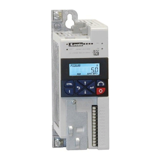
Page 4: Product Description
2 PRODUCT DESCRIPTION... -
Page 5: Mounting
3 MOUNTING 3.1 IMPORTANT NOTES DANGER! Dangerous electrical voltage ▶ All work on the drive must only be carried out in the de-energised state. Possible consequence: death or severe injuries ▶ After switching off the mains voltage, wait for at least 3 minutes before you start working. 3.2 MECHANICAL INSTALLATION VLA1 02 A240 –... - Page 6 VLA1 07 A240 All dimensions in mm...
- Page 7 VLA1 15 A240 – VLA1 22 A240 All dimensions in mm...
-
Page 8: Electrical Installation
3.3 ELECTRICAL INSTALLATION 3.3.1 1-PHASE MAINS CONNECTION 230/240 V... -
Page 9: Fusing And Terminal Data
3.3.1.1 FUSING AND TERMINAL DATA Power 0.25 0.75 Cable installation in compliance with EN 60204-1 Laying system Operation without mains choke Fuse Characteristic gG/gL or gRL Max. rated current Circuit breaker Characteristic Max. rated current Operation with mains choke Fuse Characteristic gG/gL or gRL Max. -
Page 10: Connection To The It System
3.3.2 CONNECTION TO THE IT SYSTEM NOTICE! Internal components have earth/ground potential if the IT screws are not removed. Consequence: the monitoring functions of the IT system respond. Before connection to an IT system be absolutely sure to remove the IT screws. (from size 0.75kW) -
Page 11: Commissioning
4 COMMISSIONING 4.1 IMPORTANT NOTES Incorrect settings during commissioning may cause unexpected and dangerous motor and system movements. Possible consequence: death, severe injuries or damage to property – Clear hazardous area. – Observe safety instructions and safety clearances. 4.2 BEFORE INITIAL SWITCH-ON Prevent injury to persons and damage to property. - Page 12 Carrying out the functional test Start drive: 1. Enable drive: X3/DI1 = HIGH. 2. Activate preset setpoint 1 (20 Hz) as speed setpoint: X3/DI4 = HIGH. The drive rotates with 20 Hz. 3. Optional: activate the function for the reversal of rotation direction. a) X3/DI3 = HIGH.
-
Page 13: Technical Data
5 TECHNIC L D T 5.1 STANDARDS AND OPERATING CONDITIONS Conformities 2014/35/EU Low-Voltage Directive 2014/30/EU EMC Directive (reference: CE-typical drive system) TR TC 004/2011 Eurasian conformity: safety of low voltage equipment TP TC 020/2011 Eurasian conformity: electromagnetic compatibility of technical means RoHS 2 2011/65/EU Restrictions for the use of specific hazardous materials in electric and electronic devices... -
Page 14: Technical Data
Site altitude 0 … 1000 m a.m.s.l. 1000 … 4000 m a.m.s.l. Reduce rated output current by 5 %/1000 m Pollution Degree of pollution 2 EN 61800-5-1 Vibration resistance Transport 2M2 (sine, shock) EN 60721-3-2 Operation Amplitude 1 mm Germanischer Lloyd 5 ... - Page 15 CONTENUTI Informazioni sulla sicurezza ..................................... Misure base di sicurezza ................................................Pericoli ......................................................Destinazione d’uso ..................................................Descrizione prodotto ......................................Montaggio .......................................... Note importanti ..................................................... Installazione meccanica ................................................Installazione elettrica ..................................................3.3.1 Connessione a rete monofase 230/240V ......................................... 3.3.1.1 Fusibili e terminali ............................................3.3.2 Connessione a sistema IT ............................................
-
Page 16: Informazioni Sulla Sicurezza
Le note procedurali e i dettagli sul circuito descritti in questo documento sono solo delle proposte. È compito dell’utilizzatore verificare se possono essere adattati alle particolari applicazioni. LOVATO Electric non si assume alcuna responsabilità per l’idoneità delle procedure e proposte di circuito descritte. -
Page 17: Descrizione Prodotto
2 DESCRIZIONE PRODOTTO... -
Page 18: Montaggio
3 MONT GGIO 3.1 NOTE IMPORTANTI PERICOLO! Tensione elettrica pericolosa ▶ tutte le operazioni sull’azionamento devono essere eseguite in assenza di tensione. Possibili conseguenze: morte o gravi lesioni ▶ dopo avere rimosso la tensione di alimentazione, attendere almeno 3 minuti prima di ricominciare a lavorare. 3.2 INSTALLAZIONE MECCANICA VLA1 02 A240 –... - Page 19 VLA1 07 A240 Dimensioni in mm...
- Page 20 VLA1 15 A240 – VLA1 22 A240 Dimensioni in mm...
-
Page 21: Installazione Elettrica
3.3 INSTALLAZIONE ELETTRICA 3.3.1 CONNESSIONE A RETE MONOFASE 230/240 V... -
Page 22: Fusibili E Terminali
3.3.1.1 FUSBILI E TERMINALI Potenza nominale 0.25 0.75 Installazione cavi secondo EN 60204-1 Sistema di posa Funzionamento Senza induttanza di rete Fusibile Caratteristica gG/gL o gRL Max. corrente nominale Interruttore Caratteristica Max. corrente nominale Funzionamento Con induttanza di rete Fusibile Caratteristica gG/gL o gRL Max. -
Page 23: Connessione A Sistema It
3.3.2 CONNESSIONE A SISTEMA IT NOTA! I componenti interni hanno il potenziale di terra se non viene rimossa la vite IT. Prima di collegare il dispositivo ad una rete IT è indispensabile rimuovere la vite IT dall’azionamento. (da taglia 0.75kW in su) -
Page 24: Primo Avviamento
4 PRIMO VVI MENTO 4.1 NOTE IMPORTANTI Una impostazione non corretta dei parametri durante il primo avviamento può determinare movimenti inaspettati e pericolosi del motore e della macchina comandata. Possibili conseguenze: morte, lesioni gravi e danneggiamenti. – Chiara identificazione dell’area di pericolo. –... - Page 25 Svolgimento test funzionali Avvio: 1. Avviare l’azionamento: X3/DI1 = ALTO. 2. Attivare il setpoint preset frequenza 1 (20 Hz) come setpoint di velocità: X3/DI4 = ALTO. L’azionamento ruota a 20 Hz. 3. Opzionale: attivare la funzione di inversione del senso di rotazione motore. a) X3/DI3 = ALTO.
-
Page 26: Dati Tecnici
5 D TI TECNICI 5.1 NORME E CONDIZIONI DI FUNZIONAMENTO Conformità 2014/35/EU Direttiva Bassa Tensione 2014/30/EU Direttiva EMC (con rferimento a CE) TR TC 004/2011 Eurasian conformity: sicurezza delle apparecchiature a bassa tensione TP TC 020/2011 Eurasian conformity: compatibilità elettromagnetica RoHS 2 2011/65/EU Restrizioni per l’uso di specifici materiali pericolosi in dispositivi elettrici ed elettronici... -
Page 27: Dati Tecnici
Altitudine 0 … 1000 m s.l.m.m. 1000 … 4000 m s.l.m.m. Ridurre la corrente di uscita nominale del 5 %/1000 m Inquinamento Grado di inquinamento 2 EN 61800-5-1 Vibrazioni Trasporto 2M2 (sine, shock) EN 60721-3-2 Funzionamenti Ampiezza 1 mm Germanischer Lloyd 5 ...
Need help?
Do you have a question about the VLA1 Series and is the answer not in the manual?
Questions and answers