Table of Contents
Advertisement
Available languages
Available languages
LOVATO ELECTRIC S.P.A.
24020 GORLE (BERGAMO) ITALIA
VIA DON E. MAZZA, 12
TEL. 035 4282111
FAX (Nazionale): 035 4282200
FAX (International): +39 035 4282400
L
E
E-mail info@
ovato
lectric.com
L
E
Web
www.
ovato
lectric.com
WARNING!
– Carefully read the manual before the installation or use.
– This equipment is to be installed by qualified personnel, complying to current standards, to avoid
damages or safety hazards.
– Before any maintenance operation on the device, remove all the voltages from measuring and supply inputs and short-
circuit the CT input terminals.
– The manufacturer cannot be held responsible for electrical safety in case of improper use of the equipment.
– Products illustrated herein are subject to alteration and changes without prior notice. Technical data and descriptions in
the documentation are accurate, to the best of our knowledge, but no liabilities for errors, omissions or contingencies
arising there from are accepted.
– A circuit breaker must be included in the electrical installation of the building. It must be installed close by the
equipment and within easy reach of the operator. It must be marked as the disconnecting device of the equipment:
IEC /EN 61010-1 § 6.11.3.1.
– Clean the device with a soft dry cloth; do not use abrasives, liquid detergents or solvents.
ATTENTION !
– Lire attentivement le manuel avant toute utilisation et installation.
– Ces appareils doivent être installés par un personnel qualifié, conformément aux normes en vigueur en
matière d'installations, afin d'éviter de causer des dommages à des personnes ou choses.
– Avant toute intervention sur l'instrument, mettre les entrées de mesure et d'alimentation hors tension et court-circuiter
les transformateurs de courant.
– Le constructeur n'assume aucune responsabilité quant à la sécurité électrique en cas d'utilisation impropre du
dispositif.
– Les produits décrits dans ce document sont susceptibles d'évoluer ou de subir des modifications à n'importe quel
moment. Les descriptions et caractéristiques techniques du catalogue ne peuvent donc avoir aucune valeur
contractuelle.
– Un interrupteur ou disjoncteur doit être inclus dans l'installation électrique du bâtiment. Celui-ci doit se trouver tout
près de l'appareil et l'opérateur doit pouvoir y accéder facilement. Il doit être marqué comme le dispositif d'interruption
de l'appareil : IEC/ EN 61010-1 § 6.11.3.1.
– Nettoyer l'appareil avec un chiffon doux, ne pas utiliser de produits abrasifs, détergents liquides ou solvants.
ACHTUNG!
– Dieses Handbuch vor Gebrauch und Installation aufmerksam lesen.
– Zur Vermeidung von Personen- und Sachschäden dürfen diese Geräte nur von qualifiziertem
Fachpersonal und unter Befolgung der einschlägigen Vorschriften installiert werden.
– Vor jedem Eingriff am Instrument die Spannungszufuhr zu den Messeingängen trennen und die Stromwandler
kurzschlieβen.
– Bei zweckwidrigem Gebrauch der Vorrichtung übernimmt der Hersteller keine Haftung für die elektrische Sicherheit.
– Die in dieser Broschüre beschriebenen Produkte können jederzeit weiterentwickelt und geändert werden. Die im Katalog
enthaltenen Beschreibungen und Daten sind daher unverbindlich und ohne Gewähr.
– In die elektrische Anlage des Gebäudes ist ein Ausschalter oder Trennschalter einzubauen. Dieser muss sich in
unmittelbarer Nähe des Geräts befinden und vom Bediener leicht zugänglich sein. Er muss als Trennvorrichtung für das
Gerät gekennzeichnet sein: IEC/ EN 61010-1 § 6.11.3.1.
– Das Gerät mit einem weichen Tuch reinigen, keine Scheuermittel, Flüssigreiniger oder Lösungsmittel verwenden.
ADVERTENCIA
– Leer atentamente el manual antes de instalar y utilizar el regulador.
– Este dispositivo debe ser instalado por personal cualificado conforme a la normativa de instalación
vigente a fin de evitar daños personales o materiales.
– Antes de realizar cualquier operación en el dispositivo, desconectar la corriente de las entradas de alimentación y
medida, y cortocircuitar los transformadores de corriente.
– El fabricante no se responsabilizará de la seguridad eléctrica en caso de que el dispositivo no se utilice de forma
adecuada.
– Los productos descritos en este documento se pueden actualizar o modificar en cualquier momento. Por consiguiente,
las descripciones y los datos técnicos aquí contenidos no tienen valor contractual.
– La instalación eléctrica del edificio debe disponer de un interruptor o disyuntor. Éste debe encontrarse cerca del
dispositivo, en un lugar al que el usuario pueda acceder con facilidad. Además, debe llevar el mismo marcado que el
interruptor del dispositivo (IEC/ EN 61010-1 § 6.11.3.1).
– Limpiar el dispositivo con un trapo suave; no utilizar productos abrasivos, detergentes líquidos ni disolventes.
UPOZORNĚNÍ
– Návod se pozorně pročtěte, než začnete regulátor instalovat a používat.
– Tato zařízení smí instalovat kvalifikovaní pracovníci v souladu s platnými předpisy a normami pro předcházení
úrazů osob či poškození věcí.
– Před jakýmkoli zásahem do přístroje odpojte měřicí a napájecí vstupy od napětí a zkratujte transformátory proudu.
– Výrobce nenese odpovědnost za elektrickou bezpečnost v případě nevhodného používání regulátoru.
– Výrobky popsané v tomto dokumentu mohou kdykoli projít úpravami či dalším vývojem. Popisy a údaje uvedené v katalogu nemají
proto žádnou smluvní hodnotu.
– Spínač či odpojovač je nutno zabudovat do elektrického rozvodu v budově. Musejí být nainstalované v těsné blízkosti přístroje a
snadno dostupné pracovníku obsluhy. Je nutno ho označit jako vypínací zařízení přístroje: IEC/ EN 61010-1 § 6.11.3.1.
– Přístroj čistěte měkkou utěrkou, nepoužívejte abrazivní produkty, tekutá čistidla či rozpouštědla.
AVERTIZARE!
– Citiţi cu atenţie manualul înainte de instalare sau utilizare.
– Acest echipament va fi instalat de personal calificat, în conformitate cu standardele actuale, pentru a evita
deteriorări sau pericolele.
– Înainte de efectuarea oricărei operaţiuni de întreţinere asupra dispozitivului, îndepărtaţi toate tensiunile de la intrările de măsurare
şi de alimentare şi scurtcircuitaţi bornele de intrare CT.
– Producătorul nu poate fi considerat responsabil pentru siguranţa electrică în caz de utilizare incorectă a echipamentului.
– Produsele ilustrate în prezentul sunt supuse modificărilor şi schimbărilor fără notificare anterioară. Datele tehnice şi descrierile din
documentaţie sunt precise, în măsura cunoştinţelor noastre, dar nu se acceptă nicio răspundere pentru erorile, omiterile sau
evenimentele neprevăzute care apar ca urmare a acestora.
– Trebuie inclus un disjunctor în instalaţia electrică a clădirii. Acesta trebuie instalat aproape de echipament şi într-o zonă uşor
accesibilă operatorului. Acesta trebuie marcat ca fiind dispozitivul de deconectare al echipamentului: IEC/EN 61010-1 § 6.11.3.1.
– Curăţaţi instrumentul cu un material textil moale şi uscat; nu utilizaţi substanţe abrazive, detergenţi lichizi sau solvenţi.
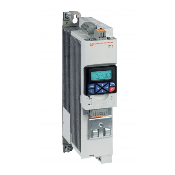
GB VARIABLE SPEED DRIVES
Installation manual
I
AZIONAMENTI A VELOCITÀ VARIABILE
Manuale di installazione
VLB...
ATTENZIONE!
– Leggere attentamente il manuale prima dell'utilizzo e l'installazione.
– Questi apparecchi devono essere installati da personale qualificato, nel rispetto delle vigenti normative
impiantistiche, allo scopo di evitare danni a persone o cose.
– Prima di qualsiasi intervento sullo strumento, togliere tensione dagli ingressi di misura e di alimentazione e
cortocircuitare i trasformatori di corrente.
– Il costruttore non si assume responsabilità in merito alla sicurezza elettrica in caso di utilizzo improprio del dispositivo.
– I prodotti descritti in questo documento sono suscettibili in qualsiasi momento di evoluzioni o di modifiche. Le
descrizioni ed i dati a catalogo non possono pertanto avere alcun valore contrattuale.
– Un interruttore o disgiuntore va compreso nell'impianto elettrico dell'edificio. Esso deve trovarsi in stretta vicinanza
dell'apparecchio ed essere facilmente raggiungibile da parte dell'operatore. Deve essere marchiato come il dispositivo di
interruzione dell'apparecchio: IEC/ EN 61010-1 § 6.11.3.1.
– Pulire l'apparecchio con panno morbido, non usare prodotti abrasivi, detergenti liquidi o solventi.
UWAGA!
– Przed użyciem i instalacją urządzenia należy uważnie przeczytać niniejszą instrukcję.
– W celu uniknięcia obrażeń osób lub uszkodzenia mienia tego typu urządzenia muszą być instalowane przez
wykwalifikowany personel, zgodnie z obowiązującymi przepisami.
– Przed rozpoczęciem jakichkolwiek prac na urządzeniu należy odłączyć napięcie od wejść pomiarowych i zasilania oraz zewrzeć
zaciski przekładnika prądowego.
– Producent nie przyjmuje na siebie odpowiedzialności za bezpieczeństwo elektryczne w przypadku niewłaściwego użytkowania
urządzenia.
– Produkty opisane w niniejszym dokumencie mogą być w każdej chwili udoskonalone lub zmodyfikowane. Opisy oraz dane
katalogowe nie mogą mieć w związku z tym żadnej wartości umownej.
– W instalacji elektrycznej budynku należy uwzględnić przełącznik lub wyłącznik automatyczny. Powinien on znajdować się w
bliskim sąsiedztwie urządzenia i być łatwo osiągalny przez operatora. Musi być oznaczony jako urządzenie służące do wyłączania
urządzenia: IEC/ EN 61010-1 § 6.11.3.1.
– Urządzenie należy czyścić miękką szmatką, nie stosować środkow ściernych, płynnych detergentow lub rozpuszczalnikow.
ПРЕДУПРЕЖДЕНИЕ!
– Прежде чем приступать к монтажу или эксплуатации устройства, внимательно ознакомьтесь с одержанием
настоящего руководства.
– Во избежание травм или материального ущерба монтаж должен существляться только квалифицированным персоналом
в соответствии с действующими нормативами.
– Перед проведением любых работ по техническому обслуживанию устройства необходимо обесточить все измерительные
и питающие входные контакты, а также замкнуть накоротко входные контакты трансформатора тока (ТТ).
– Производитель не несет ответственность за обеспечение электробезопасности в случае ненадлежащего использования
устройства.
– Изделия, описанные в настоящем документе, в любой момент могут подвергнуться изменениям или
усовершенствованиям. Поэтому каталожные данные и описания не могут рассматриваться как действительные с точки
зрения контрактов
– Электрическая сеть здания должна быть оснащена автоматическим выключателем, который должен быть расположен
вблизи оборудования в пределах доступа оператора. Автоматический выключатель должен быть промаркирован как
отключающее устройство оборудования: IEC /EN 61010-1 § 6.11.3.1.
– Очистку устройства производить с помощью мягкой сухой ткани, без применения абразивных материалов, жидких
моющих средств или растворителей.
DİKKAT!
– Montaj ve kullanımdan önce bu el kitabını dikkatlice okuyunuz.
– Bu aparatlar kişilere veya nesnelere zarar verme ihtimaline karşı yürürlükte olan sistem kurma normlarına göre
kalifiye personel tarafından monte edilmelidirler
– Aparata (cihaz) herhangi bir müdahalede bulunmadan önce ölçüm girişlerindeki gerilimi kesip akım transformatörlerinede kısa
devre yaptırınız.
– Üretici aparatın hatalı kullanımından kaynaklanan elektriksel güvenliğe ait sorumluluk kabul etmez.
– Bu dokümanda tarif edilen ürünler her an evrimlere veya değişimlere açıktır. Bu sebeple katalogdaki tarif ve değerler herhangi bir
bağlayıcı değeri haiz değildir.
– Binanın elektrik sisteminde bir anahtar veya şalter bulunmalıdır. Bu anahtar veya şalter operatörün kolaylıkla ulaşabileceği yakın
bir yerde olmalıdır. Aparatı (cihaz) devreden çıkartma görevi yapan bu anahtar veya şalterin markası: IEC/ EN 61010-1 § 6.11.3.1.
– Aparatı (cihaz) sıvı deterjan veya solvent kullanarak yumuşak bir bez ile siliniz aşındırıcı temizlik ürünleri kullanmayınız.
G
B
1
Advertisement
Chapters
Table of Contents

Related Manuals for LOVATO ELECTRIC VLB Series


Summary of Contents for LOVATO ELECTRIC VLB Series
- Page 1 GB VARIABLE SPEED DRIVES Installation manual AZIONAMENTI A VELOCITÀ VARIABILE LOVATO ELECTRIC S.P.A. Manuale di installazione 24020 GORLE (BERGAMO) ITALIA VIA DON E. MAZZA, 12 TEL. 035 4282111 FAX (Nazionale): 035 4282200 FAX (International): +39 035 4282400 E-mail info@ ovato lectric.com...
-
Page 2: Table Of Contents
CONTENTS Safety information ......................................... Residual hazards ..................................................Intended use ....................................................Product description ....................................... Electrical installation ......................................Connection plan ................................................Fuses and cable cross-sections ..............................................DC-Bus voltage operative range ..............................................Data of control connections ................................................Modbus connection ..................................................3.5.1 Connection plan ............................................... 3.5.2 Terminal data ................................................ -
Page 3: Safety Information
1 SAFETY INFORMATION 1.1 RESIDUAL HAZARDS The user must take the residual hazards mentioned into consideration in the risk assessment for his/her machine/system. If the above is disregarded, this can lead to severe injuries to persons and damage to material assets! PRODUCT Observe the warning labels on the product! ICON... - Page 4 CONNECTION TO THE IT SYSTEM Internal components have earth potential if the IT screws are not removed. Consequence: the monitoring functions of the IT system respond. Before connection to an IT system be absolutely sure to remove the IT screws. Mechanical installation - Size from 55kW to 110kW.
-
Page 5: Electrical Installation
3 ELECTRICAL INSTALLATION 3.1 CONNECTION PLAN... -
Page 6: Fuses And Cable Cross-Sections
3.2 FUSES AND CABLE CROSS-SECTIONS Rated power 0.75 Cable installation in compliance with EN 60204-1 Laying system Operation Without mains choke Fuse Characteristics gG/gL or gRL Max. rated current Circuit breaker Characteristics Max. rated current Operation With mains choke Fuse Characteristics gG/gL or gRL Max. - Page 7 Rated power Cable installation in compliance with EN 60204-1 Laying system Operation Without mains choke Fuse Characteristics gG/gL or gRL Max. rated current Circuit breaker Characteristics Max. rated current Operation With mains choke Fuse Characteristics gG/gL or gRL Max. rated current Circuit breaker Characteristics Max.
- Page 8 Rated power Cable installation in compliance with EN 60204-1 Laying system Operation Without mains choke Fuse Characteristics gG/gL or gRL Max. rated current Circuit breaker Characteristics Max. rated current Operation With mains choke Fuse Characteristics gG/gL or gRL Max. rated current Circuit breaker Characteristics Max.
- Page 9 Rated power 18.5 Cable installation in compliance with EN 60204-1 Laying system Operation Without mains choke Fuse Characteristics gG/gL or gRL Max. rated current Circuit breaker Characteristics Max. rated current Operation With mains choke Fuse Characteristics gG/gL or gRL Max. rated current Circuit breaker Characteristics Max.
- Page 10 Rated power Cable installation in compliance with EN 60204-1 Laying system Operation Fuse Characteristics Max. rated current Circuit breaker Characteristics Max. rated current Operation With mains choke Fuse Characteristics gG/gL or gRL Max. rated current Circuit breaker Characteristics Max. rated current Earth-leakage circuit breaker ≥...
-
Page 11: Dc-Bus Voltage Operative Range
Rated power Cable installation in compliance with EN 60204-1 Laying system Operation Fuse Characteristics –– Max. rated current –– Circuit breaker Characteristics –– Max. rated current –– Operation With mains choke Fuse Characteristics Max. rated current Circuit breaker Characteristics –– Max. -
Page 12: Data Of Control Connections
Data of control connections DIGITAL INPUTS Switching type PNP, NPN Parameterisable PNP switching level < +5 IEC 61131−2, type 1 HIGH > +15 NPN switching level > +15 HIGH < +5 Input resistance kΩ Cycle time can be changed by software filtering Electric strength of external volt- age ±... - Page 13 ANALOG OUTPUTS Short-circuit strength Unlimited period Electric strength of external voltage + 24V Operation as voltage output Resolution of D/A converter Output voltage DC 0 ... 10 Max. output current Max. capacitive load μF Accuracy ± 100 Typical Operation as current output Output current 0 ...
- Page 14 0.16 PTC input In the Lovato Electric setting, motor temperature monitoring is activated! In the delivery status, there is a wire jumper between the terminals T1 and T2. Before connecting a thermal sensor, remove the wire jumper. Connection of PTC or thermal contact...
-
Page 15: Modbus Connection
3.5 MODBUS CONNECTION 3.5.1 Connection plan Wiring example: Modbus network 3.5.2 Terminal data Terminal description Modbus Connection X216 Connection type Spring terminal Min. cable cross-section Max. cable cross-section Stripping length Tightening torque –– Required screwdriver 0.4x2.5 3.5.3 Basic network settings The network must be terminated with a 120Ω... -
Page 16: Connection Of The Safety Module
3.6 CONNECTION OF THE SAFETY MODULE 3.6.1 Important notes DANGER! Improper installation of the safety engineering system can cause an uncontrolled starting action of the drives. Possible consequences: death or severe injuries. – Safety engineering systems may only be installed and commissioned by qualified and skilled personnel. –... -
Page 17: Commissioning
4 COMMISSIONING 4.1 IMPORTANT NOTES Incorrect settings during commissioning may cause unexpected and dangerous motor and system movements. Possible consequence: death, severe injuries or damage to material assets. – Clear hazardous area. – Observe safety instructions and safety clearances. 4.2 BEFORE INITIAL SWITCH-ON Prevent injury to persons and damage to material assets. -
Page 18: Quick Guide For Configuration Of Vlb3 Parameters
5 QUICK GUIDE FOR CONFIGURATION OF VLB3 PARAMETERS Steps to follow for the configuration of the variable speed drive: LEARN HOW TO NAVIGATE THE MENU See chapter 5.1 RESET PARAMETERS TO DEFAULT See chapter 5.2 HOW DO YOU WANT TO COMMAND THE RUN AND STOP OF THE MOTOR? See chapter 5.3 HOW DO YOU WANT TO ADJUST... -
Page 19: Reset Parameters To Default
Example of navigation in the menu of the VSD and modification of a parameter. Back to the previous level Enter in parametrisation mode Select the group Back to the previous level Enter in the group Select the parameter Back to the previous level Confirm the parameter to modify Select the sub-parameter Back to the previous level... -
Page 20: Command The Run/Stop Of The Motor
5.3 COMMAND THE RUN/STOP OF THE MOTOR 5.3.1 2-wires control from the flexible I/O terminal block Parameter Function Setting Description P400.01 VSD enable VSD always enabled (default setting) P400.02 Run/stop command Run/stop command from digital input DI1 (connected between terminals DI1-24V) 5.3.2 From keypad Start... -
Page 21: Frequency Adjustment
5.4 FREQUENCY ADJUSTMENT 5.4.1 From keypad Increase the frequency Decrease the frequency Parameter Function Setting Description P201.01 Frequency setpoint source Frequency adjusted from keypad P210.00 Minimum frequency Insert the value of the minimum frequency P211.00 Maximum frequency 50Hz Insert the value of the maximum frequency P220.00 Acceleration time 5sec... -
Page 22: From Analog Input Signal Type 4-20Ma
5.4.4 From analog input signal type 4-20mA Analog signal 4-20mA – 2-wire sensor with output 4-20mA supplied at 24VDC – Parameter Function Setting Description P201.01 Frequency setpoint source Frequency adjusted with analog input 1 (AI1) P210.00 Minimum frequency Insert the value of the minimum frequency P211.00 Maximum frequency 50Hz... -
Page 23: From Motor Potentiometer (Mop)
5.4.6 From motor potentiometer (MOP) MOP UP MOP DOWN If the motor potentiometer is active as setpoint source, the frequency setpoint can be changed via the triggers assigned to two input contacts configured with the functions "MOP UP" (increase frequency) and "MOP DOWN"... -
Page 24: Motor Parameters
5.5 MOTOR PARAMETERS Parameter Function Setting Description P208.01 AC input voltage 400V Insert the value of the supply voltage P300.00 Motor control mode V/f characteristic control, open loop P302.00 V/f shape Linear V/f (Applications: conveyor belts, …) Quadratic V/f (Applications: pumps, fans, …) P303.01 V/f Base voltage 400V... -
Page 25: Additional Functions
5.6 ADDITIONAL FUNCTIONS 5.6.1 Configuration of the relay output function To configure the function of the relay output with changeover contact (terminals NO-COM-NC) is necessary to set the parameter P420.01. Here below are listed the most common functions. Parameter Function Setting Description P420.01... -
Page 26: Configuration Of The Ao1 Analog Output Function
5.6.3 Configuration of the AO1 analog output function To configure the function of the AO1 analog output (terminals AO1-GND) is necessary to set the following parameters. Parameter Function Setting Description P440.01 AO1 analog output range 0…10VDC 0…5VDC 2…10VDC 4…20mA 0…20mA P440.02 AO1 analog output function Actual output frequency (resolution 0.1 Hz) -
Page 27: Command Of Digital Inputs From Plc
5.6.5 Command of digital inputs from PLC Connection to PLC with dry contact output Connection to PLC with PNP output Connection to PLC with NPN output Connection to PLC with tensioned output 24VDC Note. Set P410.01 = 0 (digital inputs assertion level = low) 5.6.6 Configuration of the automatic (PID) / manual (frequency regulation) mode Sensor with... - Page 28 Manual mode (MAN) In MAN mode the PID control is de-activated and the variable speed drive works with manual regulation of the frequency setpoint via a potentiometer connected to the AI2 analog input (type 0-10V). In this example we configure the variable speed drive to provide an output frequency of 0Hz when the potentiometer is at minimum of its regulation scale (0V) and a frequency of 50Hz when the potentiometer is at maximum (10V).
-
Page 29: Control Of The Variable Speed Drive By Excrdu1 Remote Keypad
5.6.7 Control of the variable speed drive by EXCRDU1 remote keypad EXCRDU1 remote display unit can control up to 32 starters in contemporary at choice between variable speed drives VLB3 series and soft starters ADXL series, connected in RS485. NOTE. –... -
Page 30: Common Error Codes
Parameter Description Meaning P201.01 Frequency setpoint source Setpoint specified via network P201.02 PID setpoint source PID setpoint specified via network P400.37 Network enable Network enabled P510.01 Serial node address 1-255 Modbus serial node P510.02 Baud rate 38400bps P510.03 Data format 8 data bits, even parity, 1 stop bit P515.01 Response to timeout... -
Page 31: Technical Data
6 TECHNICAL DATA 6.1 STANDARDS AND OPERATING CONDITIONS Conformities 2014/35/EU Low-Voltage Directive 2014/30/EU EMC Directive (reference: CE-typical drive system) TR TC 004/2011 Eurasian conformity: Safety of low voltage equipment TP TC 020/2011 Eurasian conformity: Electromagnetic compatibility of technical means RoHS2 2011/65/EU Restrictions for the use of specific hazardous materials in electric and electronic devices Approvals... -
Page 32: Rated Data
Site altitude 0 … 1000 m a.m.s.l. 1000 … 4000 m a.m.s.l. Reduce rated output current by 5 %/1000 m Pollution Degree of pollution 2 EN 61800-5-1 Vibration resistance Transport EN 60721-3-2 Operation Amplitude 1 mm Germanischer Lloyd 5 ... 13.2 Hz acceleration resistant up to 0.7 g 13.2 ... - Page 33 Code VLB3 0015 A480 VLB3 0022 A480 VLB3 0040 A480 Rated power (heavy load / standard load) 1.5 / – 2.2 / – 4 / 5.5 Mains voltage Rated: 3/PE AC 400…480V, 50/60Hz. Range: 3/PE AC 340 ... 528 V, 45 Hz ... 65 Hz Rated mains current (heavy load / standard load) without mains choke 5.4 / –...
- Page 34 Code VLB3 0055 A480 VLB3 0075 A480 VLB3 0110 A480 VLB3 0150 A480 Rated power (heavy load / standard load) 5.5 / 7.5 7.5 / 11 11 / 15 15 / 18.5 Mains voltage Rated: 3/PE AC 400…480V, 50/60Hz. Range: 3/PE AC 340 ... 528 V, 45 Hz ... 65 Hz Rated mains current (heavy load / standard load) without mains choke 17.2 / 18.3...
- Page 35 Code VLB3 0185 A480 VLB3 0220 A480 VLB3 0300 A480 VLB3 0370 A480 Rated power (heavy load / standard load) 18.5 / 22 22 / 30 30 / 37 37 / 45 Mains voltage Rated: 3/PE AC 400…480V, 50/60Hz. Range: 3/PE AC 340 ... 528 V, 45 Hz ... 65 Hz Rated mains current (heavy load / standard load) without mains choke 48.4 / –...
- Page 36 Code VLB3 0450 A480 VLB3 0550 A480 VLB3 0750 A480 Rated power (heavy load / standard load) 45 / 55 55 / 75 75 / 90 Mains voltage Rated: 3/PE AC 400…480V, 50/60Hz. Range: 3/PE AC 340 ... 528 V, 45 Hz ... 65 Hz Rated mains current (heavy load / standard load) without mains choke –...
- Page 37 Code VLB3 0900 A480 VLB3 1100 A480 Rated power (heavy load / standard load) 90 / 110 110 / 132 Mains voltage Rated: 3/PE AC 400…480V, 50/60Hz. Range: 3/PE AC 340 ... 528 V, 45 Hz ... 65 Hz Rated mains current (heavy load / standard load) without mains choke –...
- Page 38 CONTENUTI Informazioni sulla sicurezza ..................................... Pericoli ......................................................Destinazione d’uso ..................................................Descrizione prodotto ......................................Installazione elettrica ......................................Lay-out connessioni ................................................Fusibili e sezione cavi ................................................Tensione operativa del bus-DC ..............................................Dati dei terminali di controllo ................................................ Connessione Modbus ................................................... 3.5.1 Lay-out connessioni ..............................................3.5.2 Terminali ................................................
-
Page 39: Informazioni Sulla Sicurezza
1 INFORMAZIONI SULLA SICUREZZA 1.1 PERICOLI L'utente deve prendere in considerazione i rischi residui citati nella valutazione del rischio per il suo impianto o la sua macchina. Se quanto sopra viene ignorato, si possono ingenerare gravi lesioni alle persone e danni ai materiali installati! PRODOTTI Prestare attenzione alle targhette di Warning apposte sui prodotti! ICONE... - Page 40 CONNESSIONE A RETE IT I componenti interni hanno il potenziale di terra se non viene rimossa la vite IT. Prima di collegare il dispositivo ad una rete IT è indispensabile rimuovere la vite IT dall’azionamento. Taglie da 55kW a 110kW Installazione della piastra per la connessione dello schermo del cavo motore.
-
Page 41: Installazione Elettrica
3 INSTALLAZIONE ELETTRICA 3.1 LAYOUT CONNESSIONI S1 Start/Stop Q1 Contattore Fusibili –– – Linea tratteggiata = Opzioni... -
Page 42: Fusibili E Sezione Cavi
3.2 FUSIBILI E SEZIONE CAVI Potenza nominale 0.75 Installazione cavi secondo EN 60204-1 Sistema di posa Funzionamento Senza induttanza di rete Fusibile Caratteristiche gG/gL o gRL Max. corrente nominale Interruttore Caratteristiche Max. corrente nominale Funzionamento Con induttanza di rete Fusibile Caratteristiche gG/gL o gRL Max. - Page 43 Potenza nominale Installazione cavi secondo EN 60204-1 Sistema di posa Funzionamento Senza induttanza di rete Fusibile Caratteristiche gG/gL o gRL Max. corrente nominale Interruttore Caratteristiche Max. corrente nominale Funzionamento Con induttanza di rete Fusibile Caratteristiche gG/gL o gRL Max. corrente nominale Interruttore Caratteristiche Max.
- Page 44 Potenza nominale Installazione cavi secondo EN 60204-1 Sistema di posa Funzionamento Senza induttanza di rete Fusibile Caratteristiche gG/gL o gRL Max. corrente nominale Interruttore Caratteristiche Max. corrente nominale Funzionamento Con induttanza di rete Fusibile Caratteristiche gG/gL o gRL Max. corrente nominale Interruttore Caratteristiche Max.
- Page 45 Potenza nominale 18.5 Installazione cavi secondo EN 60204-1 Sistema di posa Funzionamento Senza induttanza di rete Fusibile Caratteristiche gG/gL o gRL Max. corrente nominale Interruttore Caratteristiche Max. corrente nominale Funzionamento Con induttanza di rete Fusibile Caratteristiche gG/gL o gRL Max. corrente nominale Interruttore Caratteristiche Max.
- Page 46 Potenza nominale Installazione cavi secondo EN 60204-1 Sistema di posa Funzionamento Fusibile Caratteristiche Max. corrente nominale Interruttore Caratteristiche Max. corrente nominale Funzionameto Con induttanza di rete Fusibile Caratteristiche gG/gL o gRL Max. corrente nominale Interruttore Caratteristiche Max. corrente nominale Interruttore differenziale ≥...
-
Page 47: Tensione Operativa Del Bus-Dc
Potenza nominale Installazione cavi second EN 60204-1 Sistema di posa Funzionamento Fusibile Caratteristiche Max. corrente nominale Interruttore Caratteristiche Max. corrente nominale Funzionamento Con induttanza di rete Fusibile Caratteristiche Max. corrente nominale Interruttore Caratteristiche Max. corrente nominale Interruttore differenziale ≥ 300 mA, tipo B Connessione a rete trifase Connessione potenza Connessione... -
Page 48: Dati Dei Terminali Di Controllo
3.4 Dati dei terminali di controllo INGRESSI DIGITALI Tipologia di logica PNP, NPN Parametrizzabile PNP livello di commutazione BASSO < +5 IEC 61131−2, tipo 1 ALTO > +15 NPN livello di commutazione BASSO > +15 ALTO < +5 Resistenza di ingresso kΩ... - Page 49 USCITE ANALOGICHE Resistenza al corto circuito Periodo illimitato Resistenza elettrica a tensione esterna + 24V Funzionamento come uscita in tensione Risoluzione convertitore D/A Uscita tensione DC 0 ... 10 Max. corrente di uscita Max. carico capacitivo μF Accuratezza ± 100 Tipico Funzionamento come uscita in corrente Corrente di uscita...
- Page 50 DC 240 V 0.16 Ingresso PTC Nei settaggi Lovato Electric, il monitoraggio della temperatura del motore è attivato! Di default è presente un ponticello tra i terminali T1 e T2. Prima di collegare un sensore termico, rimuovere il ponticello. Utilizzo...
-
Page 51: Connessione Modbus
3.5 CONNESSIONE MODBUS 3.5.1 LAY-OUT CONNESSIONI Esempio connessione Modbus 3.5.2 TERMINALI Descrizione terminali Modbus Connessione X216 Tipo connessione A molla Min sezione cavo mm² Max sezione cavo mm² Cavo intestato Coppia serraggio Tipo avvitatore 0.4 x 2.5 3.5.3 IMPOSTAZIONE DELLA RETE La rete deve terminare fisicamente con un resistore da 120 Ohm posto al primo e all’ultimo nodo. -
Page 52: Connessione Modulo Sicurezza
3.6 CONNESSIONE MODULO SICUREZZA 3.6.1 Note importanti PERICOLO! Una installazione inappropriata del Sistema di sicurezza può determinare una azione incontrollata dell’azionamento. – I sistemi di sicurezza possono essere installati e commissionati da personale qualificato. – Tutti i componenti di controllo (switches, relays, PLC, ...) ed i quadri elettrici devono soddisfare i requisiti delle norme EN ISO 13849−1 e EN ISO13849−2. –... -
Page 53: Primo Avviamento
4 PRIMO AVVIAMENTO 4.1 NOTE IMPORTANTI Una impostazione non corretta dei parametri durante il primo avviamento può determinare movimenti inaspettati e pericolosi del motore e della macchina comandata. Possibili conseguenze: morte, infrazioni di legge e danneggiamenti. – Chiara identificazione dell’area di pericolo. –... -
Page 54: Guida Rapida Per La Configurazione Dei Parametri Del Vlb3
5 GUIDA RAPIDA PER LA CONFIGURAZIONE DEI PARAMETRI DEL VLB3 Passaggi da seguire per la configurazione: IMPARA COME NAVIGARE TRA I MENU Vedi il capitolo 5.1 RESETTA I PARAMETRI AI VALORI DI FABBRICA Vedi il capitolo 5.2 COME VUOI COMANDARE LA MARCIA E L’ARRESTO DEL MOTORE? Vedi il capitolo 5.3 COME VUOI REGOLARE LA FREQUENZA? -
Page 55: Reset Parametri Alle Impostazioni Di Fabbrica (Default)
Esempio di navigazione nei menu dell’azionamento. Sali di un livello Entra nel menu dei gruppi Scegli il gruppo Sali di un livello Entra nel gruppo Scegli il parametro Sali di un livello Conferma il parametro da modificare Scegli il sub-parametro Sali di un livello Conferma il sub-parametro da modificare senza salvare... -
Page 56: Comandi Di Marcia/Arresto Del Motore
5.3 COMANDI DI MARCIA/ARRESTO DEL MOTORE 5.3.1 Da contatto in morsettiera Parametro Funzione Valore Descrizione P400.01 Abilitazione azionamento a velocità variabile Azionamento a velocità variabile sempre abilitato (default) P400.02 Comando di marcia/arresto Comando di marcia/arresto da ingresso digitale DI1 (connesso ai terminali DI1-24V) 5.3.2 Da tastiera a bordo azionamento Start Stop... -
Page 57: Regolazione Della Frequenza
5.4 REGOLAZIONE DELLA FREQUENZA 5.4.1 Da tastiera a bordo azionamento Aumenta la frequenza Diminuisce la frequenza Parametro Funzione Valore Descrizione P201.01 Sorgente setpoint frequenza Regolazione frequenza da tastiera a bordo azionamento P210.00 Frequenza minima Inserire valore frequenza minima P211.00 Frequenza massima 50Hz Inserire valore frequenza massima P220.00... -
Page 58: Da Segnale Analogico 4-20Ma
5.4.4 Da segnale analogico 4-20mA Segnale Analogico 4-20mA – Sensore a due fili con uscita 4-20mA alimentato 24VDC – Parametro Funzione Valore Descrizione P201.01 Sorgente setpoint frequenza Regolazione frequenza da ingresso analogico AI1 P210.00 Frequenza minima Inserire valore frequenza minima P211.00 Frequenza massima 50Hz... -
Page 59: Da Motopotenziometro (Mop)
5.4.6 Da motopotenziometro (MOP) MOP UP MOP DOWN Per “motopotenziometro” si intende la possibilità di regolare la frequenza tramite due contatti in morsettiera, programmati rispettivamente con le funzioni “MOP UP” (incremento frequenza) e “MOP DOWN” (decremento frequenza). Parametro Funzione Valore Descrizione P400.04 Funzione reset allarmi (default: DI2) -
Page 60: Parametri Motore
5.5 PARAMETRI MOTORE Parametro Funzione Valore Descrizione P208.01 Tensione di rete AC 400V Impostare tensione di rete P300.00 Modalità di controllo motore Caratteristica V/f in anello aperto P302.00 Caratteristica V/f V/f lineare (Applicazioni: nastro trasportatore, …) V/f quadratica (Applicazioni: pompe, ventilatori, …) P303.01 Tensione base V/f 400V... -
Page 61: Funzioni Aggiuntive
5.6 FUNZIONI AGGIUNTIVE 5.6.1 Configurazione della funzione dell’uscita a relè Per configurare la funzione dell’uscita a relè con contatto in scambio (terminali NO-COM-NC) è necessario impostare il parametro P420.01. Di seguito vengono riportati gli esempi di impostazione più comuni. Parametro Funzione Valore Descrizione... -
Page 62: Configurazione Della Funzione Dell'uscita Analogica Ao1
5.6.3 Configurazione della funzione dell’uscita analogica AO1 Per configurare la funzione dell’uscita analogica AO1 (terminali AO1-GND) è necessario impostare i seguenti parametri. Parametro Funzione Valore Descrizione P440.01 Range dell’uscita analogica 0…10VDC 0…5VDC 2…10VDC 4…20mA 0…20mA P440.02 Segnale associato all’uscita analogica Frequenza di uscita (risoluzione 0.1Hz) Setpoint di frequenza (risoluzione 0.1Hz) Ingresso analogico 1 (risoluzione 0.1%) -
Page 63: Comando Ingressi Digitali Da Plc
5.6.5 Comando ingressi digitali da PLC Connessione a PLC con uscita a contatto pulito Connessione a PLC con uscita PNP Connessione a PLC con uscita NPN Connessione a PLC con uscita tensionata 24V Nota. Impostare P410.01 = 0 (livello attivazione ingressi digitali = basso) 5.6.6 Gestione funzionamento modalità... - Page 64 Modalità manuale (MAN) In modalità MAN il controllo PID è disabilitato e la regolazione della frequenza dell’azionamento viene fatta manualmente tramite un potenziometro connesso all’ingresso analogico AI2 (tipo 0-10V). In questo esempio configuriamo l’azionamento per fornire una frequenza di uscita di 0Hz quando il potenziometro è al minimo della sua scala di regolazione (0V) e una frequenza di 50Hz quando il potenziometro è al massimo (10V).
-
Page 65: Controllo Dell'azionamento Tramite Tastiera Remota Excrdu1
5.6.7 Controllo dell'azionamento tramite unità remota Lovato EXCRDU1 All’unità EXCRDU1 è possibile connettere contemporaneamente su bus seriale RS485 fino a 32 dispositivi a scelta tra azionamenti a velocità variabile VLB3 e soft starter ADXL NOTE – I terminali “TA” e “TB” della porta RS485 dei VLB3 hanno polarità invertita rispetto ai terminali “A”... -
Page 66: Codici Di Errore Comuni
Parametro Descrizione Impostazione Significato P201.01 Sorgente setpoint frequenza Setpoint frequenza impostato da rete P201.02 Sorgente setpoint PID Setpoint PID impostato da relè P400.37 Abilitazione rete Rete abilitata P510.01 Indirizzo seriale nodo 1-255 Nodo seriale Modbus P510.02 Velocità seriale 38400bps P510.03 Formato dati 8 bit dati, parità... -
Page 67: Dati Tecnici
6 DATI TECNICI 6.1 NORME E CONDIZIONI DI FUNZIONAMENTO Conformità 2014/35/EU Direttiva Bassa Tensione 2014/30/EU Direttiva EMC (con riferimento a CE) TR TC 004/2011 Eurasian conformity: Safety of low voltage equipment TP TC 020/2011 Eurasian conformity: Compatibilità elettromagnetica RoHS 2 2011/65/EU Restrizioni su utilizzo ristretto negli ambienti Omologazioni... -
Page 68: Dati Tecnici
Altitudine 0 … 1000 m s.l.m.m 1000 … 4000 m s.l.m.m Riduzione della corrente di uscita del 5 %/1000 m Polveri Grado 2 EN 61800-5-1 Vibrazioni Trasporto EN 60721-3-2 Funzionamento Ampiezza 1 mm Germanischer Lloyd 5 ... 13.2 Hz Accelerazione 0.7 g 13.2 ... - Page 69 Codice VLB3 0015 A480 VLB3 0022 A480 VLB3 0040 A480 Potenza nominale (carico gravoso / carico normale) 1.5 / – 2.2 / – 4 / 5.5 Tensione di rete Nominale: 3/PE AC 400…480V, 50/60Hz. Limiti: 3/PE AC 340 ... 528 V, 45 Hz ... 65 Hz Corrente nominale di rete (carico gravoso / carico normale) Senza induttanza 5.4 / –...
- Page 70 Codice VLB3 0055 A480 VLB3 0075 A480 VLB3 0110 A480 VLB3 0150 A480 Potenza nominale (carico gravoso / carico normale) 5.5 / 7.5 7.5 / 11 11 / 15 15 / 18.5 Tensione di rete Nominale: 3/PE AC 400…480V, 50/60Hz. Limiti: 3/PE AC 340 ... 528 V, 45 Hz ... 65 Hz Corrente nominale di rete (carico gravoso / carico normale) Senza induttanza 17.2 / 18.3...
- Page 71 Codice VLB3 0185 A480 VLB3 0220 A480 VLB3 0300 A480 VLB3 0370 A480 Potenza nominale (carico gravoso / carico normale) 18.5 / 22 22 / 30 30 / 37 37 / 45 Tensione di rete Nominale: 3/PE AC 400…480V, 50/60Hz. Limiti: 3/PE AC 340 ... 528 V, 45 Hz ... 65 Hz Corrente nominale di rete (carico gravoso / carico normale) Senza induttanza 48.4 / –...
- Page 72 Codice VLB3 0450 A480 VLB3 0550 A480 VLB3 0750 A480 Potenza nominale (carico gravoso / carico normale) 45 / 55 55 / 75 75 / 90 Tensione di rete Nominale: 3/PE AC 400…480V, 50/60Hz. Limiti: 3/PE AC 340 ... 528 V, 45 Hz ... 65 Hz Corrente nominale di rete (carico gravoso / carico normale) Senza induttanza Con induttanza...
- Page 73 Codice VLB3 0900 A480 VLB3 1100 A480 Potenza nominale (carico gravoso / carico normale) 90 / 110 110 / 132 Tensione di rete Nominale: 3/PE AC 400…480V, 50/60Hz. Limiti: 3/PE AC 340 ... 528 V, 45 Hz ... 65 Hz Corrente nominale di rete (carico gravoso / carico normale) Senza induttanza –...
-
Page 74: Dimensions And Mechanical Installation
7 DIMENSIONS AND MECHANICAL INSTALLATION - DIMENSIONI E INSTALLAZIONE MECCANICA VLB3 0,4kW VLB3 0,75kW All dimensions in mm Dimensioni in mm... - Page 75 VLB3 1,5kW..2,2kW VLB3 4kW..5,5kW All dimensions in mm Dimensioni in mm...
- Page 76 VLB3 7,5kW ... 11kW VLB3 15kW ... 22kW All dimensions in mm Dimensioni in mm...
- Page 77 VLB3 30kW...45kW ) ) ) VLB3 55kW...75kW ) ) ) All dimensions in mm Dimensioni in mm...
- Page 78 VLB3 90kW...110kW All dimensions in mm Dimensioni in mm...
Need help?
Do you have a question about the VLB Series and is the answer not in the manual?
Questions and answers