
Related Manuals for H3C WA6320H-HI


Summary of Contents for H3C WA6320H-HI
- Page 1 H3C WA6320H-HI Access Point Installation Guide New H3C Technologies Co., Ltd. http://www.h3c.com Document version: 5W100-20230413...
- Page 2 The information in this document is subject to change without notice. All contents in this document, including statements, information, and recommendations, are believed to be accurate, but they are presented without warranty of any kind, express or implied. H3C shall not be liable for technical or editorial errors or omissions contained herein.
- Page 3 Preface This installation guide describes the installation procedure for the H3C WA6320H-HI access point. This preface includes the following topics about the documentation: • Audience. • Conventions. • Documentation feedback. Audience This documentation is intended for: • Network planners. •...
- Page 4 Symbols Convention Description An alert that calls attention to important information that if not understood or followed WARNING! can result in personal injury. An alert that calls attention to important information that if not understood or followed CAUTION: can result in data loss, data corruption, or damage to hardware or software. An alert that calls attention to essential information.
- Page 5 Documentation feedback You can e-mail your comments about product documentation to info@h3c.com. We appreciate your comments.
-
Page 6: Table Of Contents
Contents 1 Preparing for installation ·········································································· 1-1 Safety recommendations ································································································································ 1-1 Site preparation ··············································································································································· 1-1 Installation accessories ··································································································································· 1-1 Installation tools ·············································································································································· 1-2 2 Installing the AP ······················································································· 2-1 Installation flowchart········································································································································ 2-1 Pre-installation tasks ······································································································································· 2-1 Determining the installation position ··············································································································· 2-1 Mounting the AP··············································································································································... -
Page 7: Preparing For Installation
Preparing for installation Safety recommendations WARNING! Only designated authorized technical personnel can install and remove the AP and its accessories. You must read all safety instructions carefully before working with the AP. To avoid possible bodily injury and equipment damage, read the following safety recommendations before installing the AP. -
Page 8: Installation Tools
Installation tools When installing the AP, you might need the following tools. Prepare the installation tools yourself as required. Figure1-2 Installation tools... -
Page 9: Installing The Ap
Installing the AP Installation flowchart Figure2-1 Installation flowchart Pre-installation tasks Before installing the AP, perform the following tasks: • Power on the AP and connect the AP to the network. Examine the LEDs to verify that the AP is operating correctly. For information about the LEDs, see "Appendix" •... -
Page 10: Mounting The Ap
Mounting the AP Attaching the mounting bracket to an 86 panel Use the provided M4 × 30 mm pan-head screws to attach the mounting bracket to the 86 panel. Figure2-2 Attaching the mounting bracket to the 86 panel Connecting Ethernet cables Use either of the two connection methods according to the power supply mode: •... - Page 11 Figure2-3 Connecting a cable to the Ethernet copper port Connecting a cable to the Ethernet fiber port To connect the AP to the network by using fibers, install a transceiver module on the AP, and then insert the fiber connector to the transceiver module. The fiber port on the AP supports only LC connectors.
- Page 12 Figure2-4 Connecting an Ethernet fiber port Figure2-5 Fiber connection and DC power connection IMPORTANT: • Do not directly connect a transceiver module attached with a fiber into the fiber port. To connect a fiber port, first install a transceiver module and then connect the fiber. •...
-
Page 13: Mounting The Ap On The 86 Panel
• Do not bend a fiber excessively. The bending radius of a fiber cannot be less than 10 cm (3.94 in). • Make sure the fiber end face is clean. Mounting the AP on the 86 panel Align the mounting peg on the mounting bracket with the installation slot in the rear of the AP and insert the peg into the slot. -
Page 14: Connecting A Power Adapter
You can use a power adapter to connect the AP to a local power source. No power adapter is provided with the AP. As a best practice, purchase an adapter from H3C if you use a local power source. Make sure the power adapter meets the LPS or PS2 power supply requirements. -
Page 15: Connecting A Local Dc Power Source
Connecting a local DC power source No terminal block is provided with the AP. Purchase a terminal block as required. As a best practice, use copper wires with 0.5 or 0.75 mm (0.0008 or 0.0011 in ) cross sectional area. The copper wires must comply with GBT3956-1997. The output voltage range for the AP is 40 VDC to 55 VDC. -
Page 16: Verifying That The Cloud-Managed Ap Has Been Connected To The Network
AP name AP ID State Model Serial ID WA6320H-HI 219801A3AU8199E00001 Verifying that the cloud-managed AP has been connected to the network When the AP operates in cloud mode, use a wireless terminal to search for and access the wireless service provided by the AP. If you can access external networks, the AP has been connected to the... -
Page 17: Accessing The Ap
Accessing the AP When the AP operates in cloud mode, you can access and configure the AP from the console port, Web interface, or through Telnet. Accessing the AP from the Web interface or through Telnet requires the IP address of the AP. Logging in to the AP from the console port Prepare the following items for accessing the device from the console port: •... -
Page 18: Logging In To The Ap Through Telnet
Enable WLAN on the configuration terminal and access WLAN H3C_xxxxxx, where xxxxxx is the last six bits of the AP's MAC address. Visit http://wlan.h3c.com from a browser, and then press Enter. Enter the default username and password. For security purposes, change the password as... -
Page 19: Configuring The Ap From The Cloudnet Platform
Enter the username and password. After login, you can add the AP to the platform and manage the AP. For more information about platform login and device management, see H3C Cloudnet Deployment Guide. Appendix A Technical specifications Table5-1 Technical specifications... -
Page 20: Appendix B Ports And Leds
Appendix B Ports and LEDs LEDs Figure6-1 LEDs on the AP (1) Power status LED (2) Radio status LED (3) Uplink port status LED (4) Ethernet fiber port LED (5) Ethernet copper port LED NOTE: The indications of LED flashing frequencies are as follows: •... - Page 21 Status Description The port has been auto-negotiated to operate at Steady yellow 10/100 Mbps. The port is sending or receiving data at 10/100 Flashing yellow Mbps. The port has been auto-negotiated to operate at Steady green 1000 Mbps. Flashing green The port is sending or receiving data at 1000 Mbps.
-
Page 22: Ports
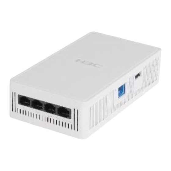
Status Description Mbps. The port has been auto-negotiated to operate at Steady green 1000 Mbps. Flashing green The port is sending or receiving data at 1000 Mbps. No link is present on the port. The port has been auto-negotiated to operate at Steady yellow 10/100 Mbps. - Page 23 • One GE/SFP port • One Uplink/PoE+ port • One USB port It provides also a reset button (RST). Figure6-2 Ports on the AP (1) 10/100/1000M Ethernet copper ports (1) Reset button (RST) (2) Console port (3) USB port...
- Page 24 (1) GE/SFP port (2) Uplink/PoE+ port (3) 54 VDC power port Table6-4 Port descriptions Standards and Port Description protocols Used by technical personnel only for device Console port RS/EIA-232 configuration and management. • IEEE802.3 Represented by interface number GE1/0/2 to •...
-
Page 25: Appendix C Transceiver Modules
Appendix C Transceiver modules The MM string in a transceiver module name indicates that the module supports multi-mode optical fibers and the SM string indicates that the module supports single-mode optical fibers. The supported transceiver modules may be updated as time changes. For accurate transceiver module information, contact the marketing personnel or Technical Support.
Need help?
Do you have a question about the WA6320H-HI and is the answer not in the manual?
Questions and answers