
Related Manuals for H3C WA6628E-T


Summary of Contents for H3C WA6628E-T
- Page 1 H3C WA6628E-T Access Point Installation Guide New H3C Technologies Co., Ltd. http://www.h3c.com Document version: 5W100-20201125...
- Page 2 The information in this document is subject to change without notice. All contents in this document, including statements, information, and recommendations, are believed to be accurate, but they are presented without warranty of any kind, express or implied. H3C shall not be liable for technical or editorial errors or omissions contained herein.
- Page 3 Preface This installation guide describes the installation procedure for the WA6628E-T access point. This preface includes the following topics about the documentation: • Audience. • Conventions. • Documentation feedback. Audience This documentation is intended for: • Network planners. • Field technical support and servicing engineers.
- Page 4 Symbols Convention Description An alert that calls attention to important information that if not understood or followed WARNING! can result in personal injury. An alert that calls attention to important information that if not understood or followed CAUTION: can result in data loss, data corruption, or damage to hardware or software. An alert that calls attention to essential information.
- Page 5 Documentation feedback You can e-mail your comments about product documentation to info@h3c.com. We appreciate your comments.
-
Page 6: Table Of Contents
Contents 1 Preparing for installation ·········································································· 1-1 Safety recommendations ································································································································ 1-1 Site preparation ··············································································································································· 1-1 Installation accessories ··································································································································· 1-2 Installation tools ·············································································································································· 1-2 2 Installing the AP ······················································································· 2-1 Installation flowchart········································································································································ 2-1 Pre-installation tasks ······································································································································· 2-1 Determining the installation position ··············································································································· 2-1 Mounting the AP··············································································································································... -
Page 7: Preparing For Installation
Preparing for installation Safety recommendations WARNING! Only professional technical engineers are allowed to install and remove the AP and its accessories. Read the safety instructions carefully before installing or servicing the AP. To avoid possible bodily injury and equipment damage, read the following safety recommendations before installing the AP. -
Page 8: Installation Accessories
Installation accessories Figure1-1 Installation accessories × 4 × 4 Cage nut M6 screw Wall-mount brackets Mounting brackets WAGO power (user supplier) (user supplied) (user supplied) (user supplied) connector × 8 M4 screw Grounding cable Lightning arrester Load (optional) (user supplied) (user supplied) (optional) Installation tools... -
Page 9: Installing The Ap
Installing the AP Installation flowchart Figure2-1 Installation flowchart Start Pre-installation tasks Install the AP Wall-mount the AP Rack-mount the AP Connect the grounding cable Connect RF cables Connect an optical fiber Connect M12 cables Connect the power cord Connect the AP to the network Pre-installation tasks Before installing the AP, perform the following tasks: •... -
Page 10: Mounting The Ap
• Make sure the AP does not hinder people’s daily work and life. • Do not install the AP under water seeping, dripping, soaking, or condensing environment and prevent water droplets from flowing into the AP along cables. • Install the AP in a location accessible only to professional technical engineers, and the installation and maintenance of AP must be performed by professional technical engineers. -
Page 11: Mounting The Ap On A Wall
Figure2-3 Mounting brackets Mounting the AP on a wall Use M4 screws to attach the wall-mount brackets to the AP and fasten the screws. Figure2-4 Attaching the wall-mount brackets to the AP PH2# 1.4N·m Use M6 screws to attach the AP to a power distribution cabinet. -
Page 12: Mounting The Ap In A Rack
Figure2-5 Attaching the AP to a power distribution cabinet PH3# 5N·m Mounting the AP in a rack Wear an ESD wrist strap. Make sure the wrist strap makes good skin contact and is reliably grounded. Make sure the rack is stable and reliably grounded. Use the mounting brackets to mark the cage nut installation positions on the rack posts and then install cage nuts. - Page 13 Figure2-7 Attaching mounting brackets to the AP PH2# 1.4N·m Supporting the bottom of the AP with one hand and holding the front of the AP with the other, gently push the AP into the rack. Then use M6 rack screws and cage nuts to attach the mounting brackets to the rack posts.
-
Page 14: Connecting The Grounding Cable
Connecting the grounding cable CAUTION: • Correctly connecting the grounding cable is crucial to lightning protection and EMI protection. Before installing or using the AP, connect a grounding cable to the AP correctly. • Connect the grounding cable to the engineering ground in the equipment room. Do not connect it to a fire main or lightning rod. - Page 15 IMPORTANT: Radio 1 operates in the 5 GHz band. Radio 2 can operate in either 2.4 GHz or 5 GHz band. An RF cable is used to connect an antenna port to an external antenna. To connect an RF cable: Remove the weatherproof cap from the antenna port on the AP.
-
Page 16: Connecting An Optical Fiber
Connecting an optical fiber To connect the fiber port on the AP to the network, first install a transceiver module in the fiber port and then connect an optical fiber to the transceiver module. The fiber port on the AP supports only optical fibers with an LC connector. -
Page 17: Connecting The Power Cord
No M12 cable is provided with the AP, you can purchase or make an M12 cable yourself as required. Table2-1 describes the M12 connector pinouts against the RJ-45 connector. Table2-1 M12 connector pinouts against the RJ-45 connector Signal name RJ45 Cable color TD1+ Orange/White... - Page 18 Figure2-14 Connecting the power cord to a Wago connector Connecting a DC power cord Make sure the AP is reliably grounded. Connect one end of the DC power cord to the power port on the AP and the other end to a local power source.
-
Page 19: Connecting The Ap To The Network
Connecting an AC power cord Make sure the AP is reliably grounded. Connect one end of the AC power cord to the power port on the AP and the other end to a local power source. Figure2-16 Connecting an AC power cord Power port on the AP Name Pin No. -
Page 20: Verifying Network Connectivity When The Ap Operates In Fat Mode
M = Master, B = Backup AP name AP ID State Model Serial ID WA6628E-T 219801A2ES8209E00014 Verifying network connectivity when the AP operates in fat mode When the AP operates in fat mode, use the command on it to ping the uplink network device. -
Page 21: Accessing The Ap
Accessing the AP IMPORTANT: The AP is typically installed on a high position. As a best practice, log in to and configure the AP before installing it. This section applies only when the AP operates in fat mode. When the AP operates in fat mode, you can log in to the AP from the console port, Web interface, or through Telnet. -
Page 22: Setting Parameters For The Configuration Terminal
Setting parameters for the configuration terminal To configure and manage the AP from the console port, you must run a terminal emulator program, such as TeraTermPro, on your configuration terminal. You can use the emulator program to connect a network device, a Telnet site, or an SSH site. For more information about the terminal emulator programs, see the user guides for these programs. -
Page 23: Appendix A Technical Specifications
Appendix A Technical specifications Table4-1 Technical specifications Item Specification Dimensions (H × W × D) 40 × 260 × 210 mm (1.57 × 10.24 × 8.27 in) Weight 2.4 kg (5.29 lb) Antenna External antenna Power consumption 8 W to 40 W Radios Protocols and standards IEEE802.11a/b/g/n/ac/ax... -
Page 24: Appendix B Ports And Leds
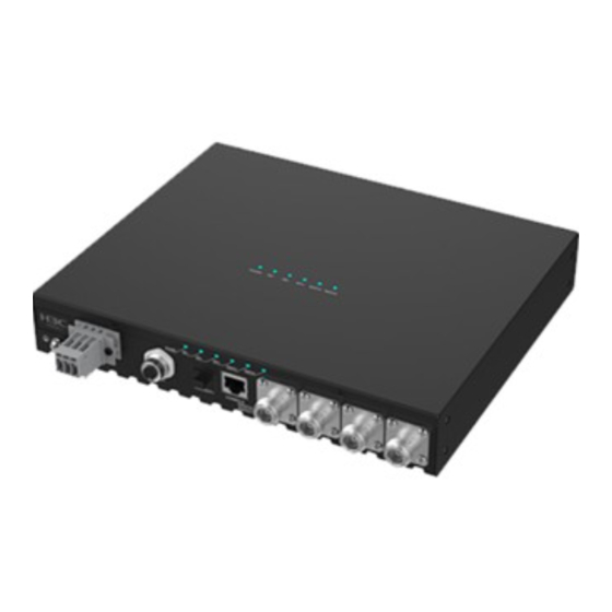
Appendix B Ports and LEDs Ports The AP provides the following ports: • One power port • One 10 GE Ethernet fiber port • Two 10/100/1000M Ethernet ports with an M12 connector • One console port • Four 5G antenna ports •... -
Page 25: Leds
Standards and Port Description protocols Used for connecting the AP to an uplink device for Internet or MAN access. • IEEE802.3 It is represented by interface number GE1/0/1 GE1/GE2 • IEEE802.3u and GE1/0/2 in the MAP file and GigabitEthernet 1 and GigabitEthernet 2 for configuration on the Used for connecting the AP to an uplink device for Internet or MAN access. - Page 26 Figure5-4 Rear view of the AP Figure5-5 Top view of the AP (1) Power LED (2) Ethernet port LEDs (3) 10GE/SFP+ port LED (4) Radio LEDs Table5-2 LED descriptions Status Description The AP is initializing, or an initialization exception Steady on has occurred.
- Page 27 Status Description The AP has started up but has not registered to any Flashing at 0.5 Hz Flashing at 2 Hz The AP is upgrading the image. The AP has not been powered on or the LEDs on the AP have been turned off. Green Flashing at 1 Hz The radio has associated clients.
-
Page 28: Appendix C Transceiver Modules
Appendix C Transceiver modules Views You must use an SFP transceiver module and optical fiber with an LC connector to connect the fiber port on the AP. Figure6-1 SFP transceiver module Figure6-2 Optical fibers with LC connectors (1) LC connector (2) Optical fiber Specifications Table6-1 SFP-XG-CPRI-IR-SM1310 transceiver module specifications... - Page 29 Table6-2 SFP-XG-CPRI-LR-SM1310 specifications Item SFP-XG-CPRI-LR-SM1310 Central wavelength 1310 nm Max transmission distance 10 km (6.21 miles) Data rate 4920 to 10310 Mb/s Connector type LC connector Fiber mode 9/125 μm Fiber diameter Output power –8.2 to +0.5 dBm...
Need help?
Do you have a question about the WA6628E-T and is the answer not in the manual?
Questions and answers