Table of Contents
Advertisement
Quick Links
HYDRO POWER UNIT 1
Installation and Operation Manual
Intended for specialized personnel or expert users
Please read these instructions carefully before installing, servicing, or operating the equipment.
This manual may be modified without notice. See: www.harken.com/manuals for updated versions.
PLEASE SAVE THESE INSTRUCTIONS
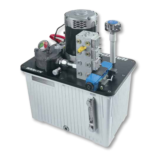
The Hydro Power Unit pictured above is for display purposes only. Actual system purchased may vary.
Advertisement
Table of Contents

Related Manuals for Harken HYDRO POWER UNIT 1


Summary of Contents for Harken HYDRO POWER UNIT 1
- Page 1 Intended for specialized personnel or expert users Please read these instructions carefully before installing, servicing, or operating the equipment. This manual may be modified without notice. See: www.harken.com/manuals for updated versions. PLEASE SAVE THESE INSTRUCTIONS The Hydro Power Unit pictured above is for display purposes only. Actual system purchased may vary.
-
Page 2: Table Of Contents
Table of Contents INTRODUCTION .............................. 3 UNIT SELECTION AND PARTS LIST ........................4 SAFETY INFORMATION ..........................5 – 6 POWER UNIT INSTALLATION ........................7 – 8 Planning installation Location in boat Secure power unit Mount control box HYDRAULIC INSTALLATION ......................... 9 – 11 Hose and fitting selection recommendation Hose shortening End fittings... -
Page 3: Introduction
Introduction Harken Hydraulic Power Units (HPU) are the complete power solution. Offered in three sizes (Hydro 1, 2 and 3), the HPU can power functions including winches, furlers, sail trim cylinders, windlasses and keel cylinders. HPUs can include waterproof, prewired electronic control boxes (ECB) or act as stand–alone, central or supplemental power units. -
Page 4: Unit Selection And Parts List
3. Compare total flow/pressure required for each piece to table below to select power unit. Harken Hydro Power Units are available in three sizes: Hydro 1, 2 and 3. Each motor/pump combination is rated at 4 GPM/15 LPM with a maximum operating pressure of 2000 PSI/140 BAR. -
Page 5: Safety Information
Read all instructions carefully and follow all safety precautions to avoid personal injury or property damage during system operation. Harken is not responsible for damage or injury resulting from unsafe product use, lack of maintenance or incorrect product and/or system operation. Contact Harken with questions regarding safety precautions and operations. If you lack training on hydraulic safety, consult a hydraulic distribution or service center for a hydraulic safety course. - Page 6 Safety Safety Requirements The instructions provided with this manual are for installation and use only. The Harken Power Unit must only be serviced by a qualified hydraulic technician. For repair service, contact Harken to find the repair site nearest you.
-
Page 7: Power Unit Installation
Installation While unpacking the hydraulic power unit (HPU) and electronic control box (ECB), inspect for irregularities. During transport the power unit may have been exposed to many unusual conditions. If irregularities appear, document details and contact shipper and Harken distributor. -
Page 8: Mount Control Box
Installation Securing Hydraulic Power Unit CAUTION! The HPU was shipped cleaned and tested. Harken strongly recommends against disassembly or removal of the tank lid or the HPU components. Introduction of contaminants can cause operational problems and possibly void warranty. A mounting pad with tie downs will be required for securing the HPU to the boat. -
Page 9: Hydraulic Installation
HPU and function. When ordering, specify that all hoses are flushed, filled with clean oil and capped at point of purchase. In most conditions, Harken recommends ISO 46 grade oil*. (See Oil Equivalent Table, pg. 15) If hoses are shipped, they may not contain oil. Harken can supply flushed, clean, empty hoses if ordered when purchased. -
Page 10: Configuration
Hydraulic Installation Port Indentification Hydro 1: HPU manifold contains four (4) valve ports, making valve port selection for a given function simple. HPU remote manifold attaches via hose to port on HPU. Remote manifold pressure port Attached manifold with 1 valve. Configuration The stock configuration of Hydro 1 is internally plumbed such that valves are pre-assigned to a manifold and motor. -
Page 11: Manifold Blanking Plates
Hydraulic Installation Manifold Blanking Plates All manifold stations must have either blanking plates or valves. Once all functions have been assigned, attach blanking plates to stations not in use. Tighten #10-24 bolts to 4.1 ft-lb (5.6 N-m) torque. The unit is shipped with the number of valves ordered. Additional valves may be added if blanking plates are present. -
Page 12: Electrical Installation
Electrical Installation Harken Hydro Units include 24 volt DC motors standard. 12 volt DC motors are available by special order. If a 12 volt DC motor was specified with system, refer to 12VDC motor electrical installation supplement for additional information. -
Page 13: Connect Deck Switches To Ecb
Electrical Installation Connect Deck Switches to the ECB Install the deck switches in a convenient location. By design, two (2) deck switches are used per function. Generally, one switch would actuate the function motor in a forward direction and the other in the reverse. Example: for a furler, the (A) switch would furl and the (B) would unfurl. -
Page 14: Connect Hpu Motor And Valves To Ecb
Electrical Installation Connect HPU Motor and Valves to ECB Valve Wiring Table Each valve operates using a three-wire cable bundle with an M12 Valve Black White Blue SW1A SW1B Ground connector. SW2A SW2B Ground Note: Valve wires supplied are 5M. These can be extended with a SW3A SW3B Ground... -
Page 15: Commissioning
Hydraulic Oil Harken recommends mineral-based, ISO 46 grade oil. Refer to Oil Equivalent Table below. If HPU is primarily used in an extreme cold weather environment, ISO 32 is suitable. -
Page 16: Leak Check
Most foreign particles flush into the return filters after first few hours of operation. If system was exposed at any time to possible contamination, replace filter element. If you have any questions, contact your Harken Tech Service Representative. Hydro 1... -
Page 17: Operation
Motor Thermal Protection Harken standard Hydro Power Units feature a 4kW 24VDC series wound motor. (12VDC motor available by special order) Motors are specified to provide years of service under standard operating conditions. -
Page 18: Filter Element Replacement Schedule
Maintenance Harken Hydraulic Power Units will provide years trouble free operation with proper, routine maintenance. Adherence to a maintenance schedule will lengthen component life, reduce downtime, and minimize repair costs. Typical maintenance includes regular oil changes, replacing filter elements, oil sampling and component inspection. Under normal operating conditions, the following maintenance... -
Page 19: Leakage Inspection
Maintenance Leakage Inspection After commissioning visually inspect system for leaks. Perform visual leak inspection at regular intervals. It is good practice to visually inspect for leaks prior to every use. CAUTION! If leak is present, decrease system pressure to 0 psi before tightening fittings. Cleanliness Inspection Maintain a dirt-free system. -
Page 20: Drawings And Schematics
Bill of Materials H-51332 Hydro 1... - Page 21 Exploded View Diagram FILTERED RETURN LINE PUMP SUCTION LINE (1" PIPE 8" LONG SCH 40) (3/8" PIPE 9" LONG SCH 40) NOT SHOWN PUMP TO MANIFOLD LINE HOSE & RETURN LINE HOSE (6 HOSE WITH -6 JICF END FITTINGS) Hydro 1...
- Page 22 3D Rendering Hydro 1...
- Page 23 Electrical Schematic Customer Supplied Switches GND (-) MOTOR 1 THERMAL RELAY 24 VDC POWER THERMAL SWITCH TRIPPED +24A-1 THERMAL BY PASS SWITCH MOTOR 1 THERMAL SWITCH TAS1 MOTOR 1 THERMAL RELAY +24A-2 MICO 9000-41034-0100600 MOTOR #1 VALVE1 +24A CONTROL POWER A COIL / B COIL PB1A SOL1A...
- Page 24 Valve and Switch Wiring Schematic Customer Supplied Switches VALVE CONNECTOR M12 PLUG M12 FEMALE INTERFACE CABLE PB1A PL1-2 BLUE (GND-) VALVE 1 COIL A (GND-) BLACK 1-+24 VDC 1-NOT USED SW1A +24-1 SW1A VALVE 1 A/B 2-SOL A 2-SOL A GREEN / YELLOW (GND) VALVE 1 24 VDC...
- Page 25 Suggested Wiring Practice for Motors Customer Supplied SUGGESTED WIRING PRACTICE FOR MOTORS CUSTOMER SUPPLIED BATTERIES, DISCONNECT AND FUSES PRIMARY DISCONNECT Power Supply 24 Volts 300A Time Delay Fuse 250 A 24VDC 4KW 210 FLA GND (-) SEPERATE FEED WIRES CUSTOMER SUPPLIED Hydro 1...
- Page 26 Control Box Mounting Dimensions H-50334 198.67 7.822 180.00 7.087 298.67 280.00 340.71 359.38 11.759 11.024 13.414 14.149 240.71 9.477 259.38 10.212 145.50 132.07 5.728 5.200 Hydro 1...
- Page 27 Control Box Interior Layout MICO 1 BYPASS GREEN - ON RED -OFF PRESS TO RESET Hydro 1...
-
Page 28: Warranty
Harken warrants that each Harken product, when properly used and maintained, will be free from defects in material and workman- ship from the date of receipt of the product by the final customer. Harken products are covered by two different kinds of warranties, on the basis of the purchaser and use made of them.
Need help?
Do you have a question about the HYDRO POWER UNIT 1 and is the answer not in the manual?
Questions and answers