
Related Manuals for REHM SYNERGIC.ARC 351


Summarization of Contents
1 Introduction and System Overview
1.1 Foreword
Expresses gratitude for purchasing the welding system and highlights quality and manufacturing standards.
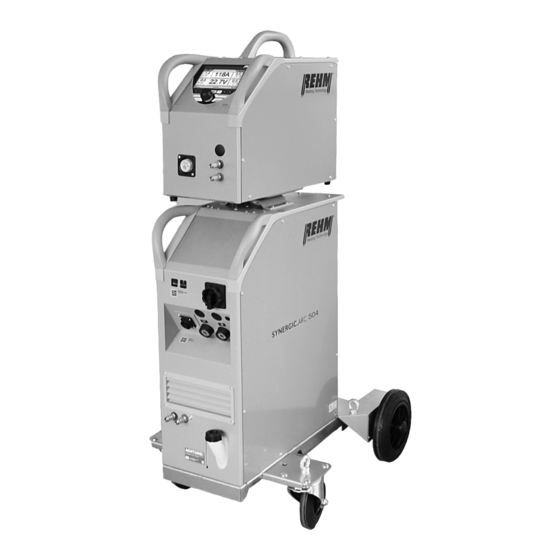
1.2 System Overview
Provides an overview of the system, its welding process, and intended applications.
1.3 Symbol Guide
Explains the meaning of typographic distinctions and safety symbols used in the manual.
2 Safety Instructions
2.1 Warning Symbols and Signals
Explains hazard signal words, pictograms in manual, and on system equipment.
2.2 Operational Requirements & Regulations
Details general notes, safety information, and regulatory compliance for system use.
2.3 Personnel & System Safety
Specifies personnel qualifications, document purpose, and mains supply requirements.
4 Functional Description
4.1 Operating Elements and Screens
Details the main screen, control panel elements, and screen functions.
4.3 Startup and Panel Features
Describes system startup procedure and special operating panel features.
5 Corner Menu Functions
5.1 Welding Process Selection
Details how to select welding processes via the corner menu (MSG, MMA, Gouging).
5.2 Operating Modes
Explains various operating modes including Two-cycle, Four-cycle, Spot, and Interval.
5.3 Characteristic Curve & Process Selection
Explains characteristic curve settings and selection of welding processes like FOCUS.ARC.
5.5 Display Panels and Settings
Details display panels for welding current, voltage, material thickness, and wire speed.
6 Submenus
6.1 MSG Parameter Configuration
Details how to set and understand various welding parameters for MSG welding.
6.2 Language Selection
Describes how to select the operating language using flags.
6.3 Job Saving and Loading
Explains how to save and load machine settings using quick-storage keys.
6.4 Setup Menu Configuration
Allows configuration of screen display, welding, and system settings.
7 Control Lamps
Control Lamp Functions
Explains the meaning of the OPERATION/excess temperature symbol.
8 Other Functions
8.1 Wire Threading and Gas Testing
Details functions for threading wire and performing gas flow tests.
8.2 System Cooling and Monitoring
Covers water cooling, temperature monitoring, fan/pump control, and polarity selection.
9 Accessories and Options
9.1 Unit Versions, Accessories & Options
Lists unit versions, torches, wear parts, miscellaneous accessories, and options.
10 Commissioning
10.1 Commissioning Safety
Stresses reading instructions and adhering to safety rules for commissioning.
10.2 Electrical Risk & Positioning
Covers working under electrical risk and safe unit placement/transport.
10.3 Connection & Cooling Procedures
Details connecting the unit, cooling, and welding cables.
10.4 Torch Connection & Wire Insertion
Guides on connecting the torch and threading the welding wire.
11 Operation
11.1 Operational Safety Checks
Stresses reading instructions and performing pre-operation checks.
11.2 Welding Hazards and Precautions
Details risks like fire, harmful substances, noise, optical radiation, electrical, and mechanical hazards.
11.3 Practical Usage Guidelines
Provides guidance on materials, consumables, torches, wire feed, and current settings.
12 Faults
12.1 Fault Handling Safety
Warns to switch off the system immediately if a hazard occurs.
12.2 Faults, Error Messages & Remedies
Lists common faults, error codes, their causes, and remedies for troubleshooting.
13 Maintenance and Repair
13.1 Safety Guidelines
Stresses that only REHM-trained personnel should perform maintenance.
13.2 Maintenance Schedule & Cleaning
Specifies recommended maintenance activities, intervals, and unit cleaning.
13.3 Water Check & Proper Disposal
Details cooling water checks and environmentally friendly disposal procedures.
14 Circuit Diagrams
Circuit Diagram Overview
Illustrates the electrical schematics of the SYNERGIC.ARC power source.
15 Components and Spare Parts
15.1 Component Identification
Lists major components and their respective item numbers and comments.
15.2 Exploded Views and Part Lists
Provides exploded views of housing parts and their associated part numbers.
16 Technical Data
Technical Specifications
Presents detailed technical specifications for the SYNERGIC.ARC series.
Need help?
Do you have a question about the SYNERGIC.ARC 351 and is the answer not in the manual?
Questions and answers