
Subscribe to Our Youtube Channel
Related Manuals for Delfi 9-2200-001BFR


Summary of Contents for Delfi 9-2200-001BFR
- Page 1 ENGLISH PTS for Blood Flow Restriction System Operator & Maintenance Manual 9-2200-001BFR delfimedical.com Pat.:www.delfimedical.com/patents...
- Page 3 SERVICED BY ANYONE OTHER THAN DELFI STAFF IN ANY WAY, OR WHICH HAS BEEN SUBJECTED TO MISUSE OR ABUSE. DISCLAIMER OF IMPLIED WARRANTIES The foregoing Express Limited Warranty is given in lieu of any and all other express or implied warranties. DELFI MAKES NO OTHER WARRANTIES INCLUDING THE IMPLIED WARRANTIES OF MERCHANTABILITY OR FITNESS FOR A PARTICULAR PURPOSE.
-
Page 4: Table Of Contents
CONTENTS GENERAL INFORMATION ....... 5 INTENDED USE ............. 5 INDICATIONS FOR USE ......... 5 CONTRAINDICATIONS .......... 5 WARNINGS ............6 PRECAUTIONS IN USE ........... 6 ADVERSE EFFECTS ..........8 SPECIFICATIONS ........... 8 GENERAL DEVICE FUNCTION ......10 EN 60601-1 CLASSIFICATION ....... 11 EMISSIONS/IMMUNITY ........ - Page 5 CONTENTS ELECTROMAGNETIC COMPATIBILITY (EMC) GUIDANCE TABLES ..........59 BFR CUFF UTILIZATION ......... 63 PRODUCT DESCRIPTION ........63 UTILIZATION ............63 CUFF INSPECTION BEFORE USE ........63 CUFF SIZE ............... 63 APPLICATION ..............64 PRESSURE SETTING ............66 INFLATION TIME ............66 REMOVAL ..............
- Page 6 CONTENTS WARNINGS, CAUTIONS & SYMBOLOGY ..79 WARNINGS, CAUTIONS & SYMBOLOGY ....79 CONTENTS...
-
Page 7: General Information
INTENDED USE This device is intended to be used only with a Delfi BFR Tourniquet Cuff by a physician or physician’s designated licensed healthcare practitioner to preoperatively and/or postoperatively exert enough pressure on the arterial blood flow in a patient’s extremity to reduce or totally occlude blood flow into the limb. -
Page 8: Warnings
Maintenance for information on testing and maintenance. PRECAUTIONS IN USE Delfi recommends that users regularly review published medical literature for factors that warrant careful consideration before performing blood flow restricted techniques. The following clinical conditions have been cited in publications as... - Page 9 • Select the proper cuff size to allow for the overlap recommended by Delfi Medical Innovations Inc. Refer to the Cuff Size guide under Section 3 BFR Cuff Utilization. Too much or too little overlap may cause cuff rolling and telescoping, unexpected release of the cuff from the limb, and/or undesired pressure distribution on the limb.
-
Page 10: Adverse Effects
(REF 7-2200-020) ~ AC Power Mains Line Voltage Range 100-240 ~ (AC), 50/60 Hz. Auto switching Line Current 175 mA RMS @ 120V ~ (AC) typical, Delfi (REF 7-2200-020) Input Power 100 watts maximum (REF 7-2200-020) AC Power Plug (North America) - Page 11 GENERAL INFORMATION Pressure Regulation ± 6 mmHg of set-point (10-second average under non-transient conditions without external leaks Inflation Timer Set-point Range 1-30 minutes, 1-minute increments Lockout Timer Set-point Range 1-10 minutes, 1-minute increments Timer Accuracy 0.1% of elapsed time Inflation Rate 34-inch cuff applied to a 30-inch thigh inflates to 350 mmHg in less than 5 seconds Deflation Rate...
-
Page 12: General Device Function
During C-BFR, the patient may perform low-intensity exercise or may remain inactive. Delfi PTS for BFR provides twelve selectable BFR protocols for BFR or C-BFR therapies. Six of these protocols are based on ORS recommendations with restricted adjustment capabilities. The remaining six protocols are fully customizable within the instrument’s limits. -
Page 13: En 60601-1 Classification
EMISSIONS/IMMUNITY The Delfi PTS for BFR complies with EMC criteria set forth in EN 60601-1-2. The user of this device should be aware that precautions should be taken in regards to EMC. The device should be installed and used according to the EMC information provided in the instructions for use. -
Page 14: Operating Instructions
We recommend that this inspection be performed by a qualified biomedical engineer or other person thoroughly familiar with electronic medical devices. If the unit is damaged, notify the carrier and Delfi immediately. If the initial inspection results are satisfactory, a functional and calibration check should be performed after a 5-hour charge. - Page 15 OPERATING INSTRUCTIONS BACK To Instrument OPERATING INSTRUCTIONS...
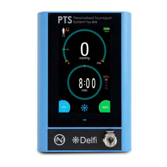
- Page 16 OPERATING INSTRUCTIONS MAIN SCREEN – DEFLATED & PTP NOT DETERMINED Power Status PROTOCOL Indicator Button / Indicator PRESSURE Button / Indicator REPs Indicator TIME Button / Indicator SETTINGS Button INFLATE PTP Button Button OPERATING INSTRUCTIONS...
- Page 17 OPERATING INSTRUCTIONS MAIN SCREEN – INFLATED & PTP DETERMINED Power Status PROTOCOL Indicator Button / Indicator PTP Indicator PRESSURE Button / Indicator LOP Indicator REST TIME Indicator REPs Indicator TIME Button / Indicator DEFLATE Button OPERATING INSTRUCTIONS...
- Page 18 Power Mains is present Hose Connector The PTS for BFR hose assembly (see below) leading to the Delfi Easi-Fit BFR Tourniquet Cuff plugs in to the PTS for BFR at the hose connector. The hose connector makes an audible ‘click’ when properly connected Hose Assembly A PTS for BFR hose assembly is supplied with each PTS for BFR.
- Page 19 Information Port The information port is used for servicing purposes only Pole Mount Bracket Attachment Used to secure the PTS for BFR to a Delfi PTS Roll Stand (REF 9-2200- Points 550). Use only Delfi (REF 9-2200-008) bracket Battery Compartment...
-
Page 20: Touchscreen Buttons And Icons
OPERATING INSTRUCTIONS TOUCHSCREEN BUTTONS AND ICONS Various colored buttons and icons are used in the PTS for BFR and described below. Button/Indicator Title Description PROTOCOL Indicates the protocol currently being used Button / Indicator The selected protocol establishes the protocol parameters when the cuff gets inflated. - Page 21 OPERATING INSTRUCTIONS Button/Indicator Title Description deflated but sees cuff pressure at a non-zero value) ~ AC Power Status Indicates that the unit is operating on ~ AC Power Indicator and charging the battery Indicates that the unit is operating on battery. Battery Status Indicator Battery charge level is indicated by the filled green color and percentage shown below the indicator...
- Page 22 OPERATING INSTRUCTIONS Button/Indicator Title Description contain an inactive REST TIME indicator NOTE: When a C-BFR protocol is being followed, the TIME indicator will display the C-BFR version TIME Indicates the remaining C-BFR time in the middle of Button / Indicator (C-BFR) the TIME indicator NOTE: When cuff is inflated, C-BFR time will count...
- Page 23 OPERATING INSTRUCTIONS Button/Indicator Title Description mode PTP Button Touch to initiate an LOP measurement, and set the INFLATE Button Touch to inflate cuff NOTE: If PTP has not been determined, the PTP Not Determined indicator will appear briefly. A subsequent touch of the INFLATE button will inflate the cuff to the pressure set-point SETTINGS Button Touch to access the Stats Menu, Protocols Menu,...
- Page 24 OPERATING INSTRUCTIONS Button/Indicator Title Description PTP Not Determined Indicates PTP has not been determined and reminds Indicator user to measure LOP and set PTP DEFLATE Button Touch to deflate cuff Touch to stop LOP measurement process, C-BFR STOP Button protocol, or leak test INCREMENT Button Touch to increment selected parameter DECREMENT Button...
- Page 25 OPERATING INSTRUCTIONS Button/Indicator Title Description ORS Upper Limb (END) ORS upper limb endurance protocol Protocol Indicator ORS Upper Limb (IPC) ORS upper limb ischemic pre-conditioning protocol Protocol Indicator ORS Lower Limb (STR) ORS lower limb strength protocol Protocol Indicator ORS Lower Limb (END) ORS lower limb endurance protocol Protocol Indicator ORS Lower Limb (IPC)
-
Page 26: Initial Setup
WARNING: Use only a Delfi (REF 7-2200-020) AC power supply and cord assembly supplied with your PTS for BFR. Do not use any other AC power supply or cord. Use of an improper power supply may cause irregular operation that could... -
Page 27: Automatic Diagnostic And Calibration Checks
Power up the unit by pressing the ON/STANDBY button and observe the following: • A welcome audio tune is sounded. A rotating Delfi logo and the product name, Personalized Tourniquet System for BFR are displayed •... - Page 28 OPERATING INSTRUCTIONS After the startup routine is completed, the Main Screen appears • “0 mmHg” is indicated in the PRESSURE indicator • If a number other than zero is indicated in the PRESSURE indicator, the unit should be calibrated by a qualified technician.
-
Page 29: Manual Tests And Checks
OPERATING INSTRUCTIONS MANUAL TESTS AND CHECKS These manual tests and checks verify certain System Functions and include Pressure and Time set-point tests and Calibration and Low-Pressure Alarm checks. Pressure Set-Point Adjustment Test: • Enter the pressure adjustment mode by touching the PRESSURE button •... - Page 30 OPERATING INSTRUCTIONS Low Pressure Alarm Test: • Connect the PTS for BFR hose assembly and a cuff to the PTS for BFR • Adjust the pressure set-point to 200 mmHg • Touch the INFLATE button to inflate the cuff • Create a leak by partially detaching the hose from the unit while the cuff is inflated •...
-
Page 31: Operation
Patient Preparation: Prepare the patient in accordance with your established procedures and Delfi’s cuff utilization instructions. Use only the patient-size appropriate PTS BFR Easi-Fit Tourniquet Cuff and the Matching Limb Protection Sleeve for the selected PTS BFR Easi-Fit Tourniquet Cuff with the PTS for BFR instrument. The... - Page 32 OPERATING INSTRUCTIONS • Connect the PTS for BFR hose assembly and a Delfi Easi-Fit BFR cuff to the unit at the hose connector WARNING: Do not allow foreign objects from entering the PTS for BFR, the hose assembly, or the cuff.
- Page 33 OPERATING INSTRUCTIONS • If the STOP button is touched, or an LOP measurement alarm is triggered, the unit will deflate the cuff, display a warning message, and allow the user to return to the Main Screen or to restart the LOP measurement •...
- Page 34 OPERATING INSTRUCTIONS BFR Therapy session: NOTE: For C-BFR therapy session procedures, go to step 6b • Touch the INFLATE button to begin a BFR therapy session • While the cuff is inflated, the TIME indicator will count down the inflation time and display the exercise time period in cyan •...
- Page 35 OPERATING INSTRUCTIONS • Touch the DEFLATE button to deflate the cuff after all exercise sets are completed • The unit will enter Lockout mode • While the unit is in Lockout mode, the unit will prevent cuff inflation and the LOCKOUT TIME indicator will count down the lockout time C-BFR Therapy Session: NOTE:...
- Page 36 OPERATING INSTRUCTIONS • After each inflated time period, the unit will automatically deflate and begin the deflated time period • The unit will repeat the inflation and deflation cycle until all inflation cycles as defined by the selected protocol have been completed •...
- Page 37 OPERATING INSTRUCTIONS Viewing Stats: • On the Main Screen, touch the SETTINGS button to open up the Settings Menu. • Touch the STATS button to enter the Stats Menu • The Stats Menu displays protocol parameters associated with the last five protocols used •...
- Page 38 OPERATING INSTRUCTIONS • To reset the Stats, touch the RESET button followed by the CONFIRM button when prompted. Refer to Stats Menu under Section 2 Operating Instructions for more information OPERATING INSTRUCTIONS...
-
Page 39: Settings
OPERATING INSTRUCTIONS SETTINGS Settings options include viewing the stats, adjusting the protocols, performing a leak test, and modifying system defaults. To access the Settings Menu, touch the SETTINGS button from the Main Screen. Refer to step 7 in Operation under Section 2 Operating Instructions. - Page 40 OPERATING INSTRUCTIONS Personalized Tourniquet Pressure Refer to Personalized Tourniquet Pressure (PTP) under Section 2 Operating Instructions Limb Occlusion Pressure Refer to Personalized Tourniquet Pressure (PTP) under Section 2 Operating Instructions Inflation Time Maximum duration in which the cuff is inflated during a BFR therapy session Inflation time will count down once the cuff is inflated.
- Page 41 OPERATING INSTRUCTIONS Cyclic BFR Toggle Switch A toggle switch to switch the selected protocol from a BFR protocol to a C-BFR protocol (or vice versa) NOTE: The Cyclic BFR Toggle Switch is only available on two fully-customizable protocols Protocol Name Protocol name may have up to 30 characters.
- Page 42 OPERATING INSTRUCTIONS • Touch to navigate between tabs • Touch a protocol to view its parameters OPERATING INSTRUCTIONS...
- Page 43 OPERATING INSTRUCTIONS Modifying a Protocol’s Parameters (ORS): • Touch an ORS protocol from the Protocols Menu • To modify a parameter, touch an adjustable parameter button and use the INCREMENT and DECREMENT buttons NOTE: For ORS protocols, some parameters cannot be modified and other parameters have restricted adjustment limits.
- Page 44 OPERATING INSTRUCTIONS NOTE: Two fully-customizable protocols can be switched between a BFR protocol and a C-BFR protocol by touching the Cyclic BFR Toggle Switch. The parameters applicable will change based on the type of protocol (BFR or C-BFR) • Touch the Protocol Name or Protocol Description boxes then use the keyboard to modify the protocol name or description NOTE:...
-
Page 45: Leak Test
OPERATING INSTRUCTIONS LEAK TEST The PTS for BFR includes an automatic test feature to check for leakage from an attached cuff, hose and connectors. To perform a leak test, follow the instructions below: Setting Up for a Leak Test: • Touch the LEAK TEST button from the Settings Menu to access the leak test •... - Page 46 OPERATING INSTRUCTIONS Leak Test Results (Passed): • If the leak test has passed, a “LEAK TEST PASSED” notification will be visible • To initiate a new leak test, touch the RETRY button • Touch the BACK button to exit the leak test and return to the Main Screen as necessary Leak Test Results (Small Leak): •...
- Page 47 OPERATING INSTRUCTIONS Leak Test Results (Large Leak): • If the leak test has failed due to a large leak, a “LARGE LEAK” notification will be visible • To initiate a new leak test, touch the RETRY button • Touch the BACK button to exit the leak test and return to the Main Screen as necessary NOTE: This indicates that there is a leak in either the test...
-
Page 48: System Defaults Menu
OPERATING INSTRUCTIONS SYSTEM DEFAULTS MENU The System Defaults Menu allows user to set the default protocol, default lockout time, alarm volume, and restore instrument to factory defaults. It also shows battery health information and the unit’s software version. The default settings will be selected when the instrument is powered ON. - Page 49 OPERATING INSTRUCTIONS Adjusting Default Parameters: • From the System Defaults Menu, touch an adjustable parameter button then use the INCREMENT and DECREMENT buttons to modify the selected default parameter • The volume can be changed to accommodate different environmental conditions so that the audio alarm can be reliably detected without being too intrusive in most situations.
-
Page 50: Personalized Tourniquet Pressure (Ptp)
OPERATING INSTRUCTIONS PERSONALIZED TOURNIQUET PRESSURE (PTP) The Delfi PTS for BFR has the capability of determining a patient’s Personalized Tourniquet Pressure (PTP) as a percentage of the patient’s Limb Occlusion Pressure (LOP) by automatically measuring LOP. The PTP percentage should be set as directed by a physician or physician’s designated licensed healthcare professional. -
Page 51: Alarm/Warning Colors And Audible Tones
OPERATING INSTRUCTIONS This type of leak could progress into a total failure of a cuff to hold pressure. To alert the operator that a substantial leak is present, a pressure alarm is declared when this type of leak is detected. If a pressure alarm occurs, and the displayed pressure is not more than 15 mmHg from the set-point, then this type of substantial leak has been detected and all cuffs and pneumatic fittings should be checked for leaks. - Page 52 OPERATING INSTRUCTIONS ALARM CONDITIONS Conditions Status Auditory Remarks and Appropriate Indicator Light Priority Tone Actions • High Pressure Flashing Red High The unit has detected high pressure in the cuff. High pressure is defined as pressure that is +15 mmHg above the pressure set- point continuously for more than 1 second...
- Page 53 OPERATING INSTRUCTIONS Conditions Status Auditory Remarks and Appropriate Indicator Light Priority Tone Actions • Cuff or hose is leaking Flashing Red High The unit has detected a large leak in the cuff, hose or connectors which is defined as the cuff failing to reach the pressure set-point in a reasonable time, or the pump running excessively...
- Page 54 OPERATING INSTRUCTIONS Conditions Status Auditory Remarks and Appropriate Indicator Light Priority Tone Actions • Cuff not fully deflated as expected Flashing Red High The unit has detected pressure in the cuff greater than 5 mmHg, 25 seconds after the cuff has been deflated •...
- Page 55 OPERATING INSTRUCTIONS • Battery fail Constant Red Technical The battery state of charge has dropped to 4% or lower and the unit has shut down in a ‘safe state’ mode*, OR • Press ON/STANDBY button to shut unit down. When cuff deflation is required, disconnect hose from cuff.
- Page 56 • If problem persists, note error code and the accompanied numeric code (if any) and contact Delfi • Cuff error during the LOP measurement Constant Yellow The unit does not detect an increase in cuff pressure...
- Page 57 OPERATING INSTRUCTIONS • Unable to determine LOP Constant Due to noisy or aberrant Yellow signals the unit cannot measure the LOP • Reapply the cuff snugly • Keep the limb and cuff still during the LOP measurement • Ensure the patient remain quiet and still Note: If the error persists after...
- Page 58 OPERATING INSTRUCTIONS • Noisy signal measured during the LOP Constant The unit has detected noise measurement Yellow in the pressure signal during the measurement of LOP and cannot determine the • Check the hose connection between the cuff and the instrument to ensure proper connection •...
- Page 59 OPERATING INSTRUCTIONS • High LOP Constant The unit has detected that Yellow the LOP is higher than the maximum allowable inflation pressure. The unit cannot determine the PTP • Reapply the cuff snugly • Keep the limb and cuff still during the LOP measurement •...
- Page 60 Restart the unit by pressing the ON/STANDBY button twice. E0012 to E0014 • failures If problem persists, note error code and the accompanied numeric code (if any) and contact Delfi E0026 to E0027 E0031 • Calibration E0016 to E0019 The unit detected a failure related to calibration •...
-
Page 61: Electromagnetic Compatibility (Emc) Guidance Tables
OPERATING INSTRUCTIONS ELECTROMAGNETIC COMPATIBILITY (EMC) GUIDANCE TABLES The following tables provide guidance on needs and installation of the PTS for BFR regarding electromagnetic compatibility. EMC GUIDANCE AND DECLARATION - EM EMISSIONS Guidance and Manufacturer's Declaration - Electromagnetic Emissions The PTS Personalized Tourniquet System for BFR is intended for use in the electromagnetic environment specified below. - Page 62 OPERATING INSTRUCTIONS EMC GUIDANCE AND DECLARATION - EM IMMUNITY/DISTURBANCES Guidance and Manufacturer’s Declaration – Electromagnetic Immunity The PTS Personalized Tourniquet System for BFR is intended for use in the electromagnetic environment specified below. The customer or the user of the PTS for BFR should ensure that it is used in such an environment. Electromagnetic Environment –...
- Page 63 OPERATING INSTRUCTIONS EMC GUIDANCE AND DECLARATION - EM EMISSIONS/RF Guidance and Manufacturer’s Declaration – Electromagnetic Immunity The PTS Personalized Tourniquet System for BFR is intended for use in the electromagnetic environment specified below. The customer or the user of the PTS for BFR should ensure that it is used in such an environment. IEC 60601 Electromagnetic Environment –...
- Page 64 OPERATING INSTRUCTIONS should be considered. If the measured field strength in the location in which the PTS Personalized Tourniquet System for BFR is used exceeds the applicable RF compliance level above, the PTS Personalized Tourniquet System for BFR should be observed to verify normal operation. If abnormal performance is observed, additional measures may be necessary, such as re-orienting or relocating the PTS Personalized Tourniquet System for BFR.
-
Page 65: Bfr Cuff Utilization
BFR CUFF UTILIZATION PRODUCT DESCRIPTION Delfi Easi-Fit BFR Tourniquet Cuffs are specifically designed for use with the PTS for BFR, featuring quick-connect connectors and patented LOP sensor technology. Easi-Fit BFR cuffs are equipped with a unique stabilizer strap / application handle and are color coded for size identification. The cuff is inflated by connecting it to the PTS for BFR, via a PTS for BFR hose assembly. -
Page 66: Application
All Delfi Easi-Fit BFR Tourniquet Cuffs are intended for use in conjunction with a Delfi Matching Limb Protection Sleeve (MLPS). Delfi strongly recommends the application of a MLPS to the limb beneath the cuff prior to the application of an Easi-Fit BFR cuff. - Page 67 BFR CUFF UTILIZATION Cuff Application: • Place a leak-free cuff on the limb and position the hose connection so that the hose will not be kinked during • Apply the cuff snugly by sliding the pivoting hook strap under the stabilizer strap / application handle Note: A cuff that is applied too loosely will reduce the effectiveness of the selected pressure.
-
Page 68: Pressure Setting
For more information on determining the Limb Occlusion Pressure, a list of references in the medical literature can be obtained from Delfi Medical Innovations Inc. upon request. To prevent damage to the Delfi Easi-Fit BFR Tourniquet Cuffs, do not inflate these cuffs to a pressure greater than 350 mmHg. -
Page 69: Removal
BFR CUFF UTILIZATION REMOVAL Transient pain upon tourniquet cuff pressure release can be lessened by elevation of the limb. If full color does not return within 3 to 4 minutes after release, the limb should be placed in a position slightly below body level. To remove cuff, follow the instructions below: Cuff Removal: •... -
Page 70: Maintenance
Delfi staff poses a risk of electric shock, damage to the unit, and injury to the patient and will void all warranties. Internal parts in the PTS for BFR can only be serviced at the factory by Delfi staff. Please contact Delfi if you have problems with... -
Page 71: Calibration
• Suitable pneumatic hoses and connectors. Note: A calibration hose set Delfi (REF 9-2200-611) can be purchased from Delfi to connect the end of the PTS for BFR hose to a pressure source and a reference pressure gauge CAUTION: The following steps must be taken in the exact order to calibrate the unit. Failure to do so may result in... - Page 72 MAINTENANCE Calibrating Zero Pressure: • Once start-up sequence completes, the unit will enter the Calibration mode and display “0 mmHg” under a PRESSURE indicator • With the hose connector on the PTS for BFR, open to atmosphere, touch the CONFIRM button to indicate zero reference pressure is applied.
- Page 73 Touch the ON/STANDBY button to turn the unit ON Note: A calibration hose set Delfi (REF 9-2200-611) can be purchased from Delfi to connect the end of the PTS for BFR hose to a reference pressure gauge Calibration Check (100 mmHg): •...
-
Page 74: Leak Testing
MAINTENANCE Maintenance for instructions on calibration Calibration Check (250 mmHg and 350 mmHg): • Repeat the previous step for 250 mmHg and 350 mmHg NOTE: If any stabilized pressure reading is off by more than 5 mmHg during the calibration check or the pressure display does not return to zero, the unit must be calibrated. -
Page 75: Battery Testing
Lithium-ion batteries • Hold new battery pack supplied by Delfi by the pull tab, ensure the 5-pin female battery connector is at the bottom and facing the male connector pins in the battery compartment. Align new battery pack with the battery compartment and push it in. - Page 76 Remove the battery, ensure the connectors are properly aligned, and re-install the battery. • WARNING: Use only Delfi Lithium-ion battery packs (REF 7-2200-046). Do not use any other batteries. Use of improper batteries may cause irregular operation that could be hazardous to the patient and/or user and may permanently damage the PTS for BFR, voiding the warranty •...
-
Page 77: Internal Hardware Servicing
Delfi staff poses a risk of electric shock, damage to the unit, and injury to the patient and will void all warranties. Internal parts in the PTS for BFR can only be serviced at the factory by Delfi staff. Please contact Delfi if you have problems with... - Page 78 STATUS indicator not working Confirm that STATUS indicator illuminate blue when unit is on illuminates during self-check upon STANDBY and is plugged in to AC power-up. Contact Delfi power STATUS indicator does not STATUS indicator not working Confirm that STATUS indicator...
-
Page 79: Replacement Parts
Deflate cuff and ensure it deflates set to STANDBY) fully (disconnect hose if required) to clear CUFF NOT DEFLATED alarm Contact Delfi. Unit can be powered Internal hardware failure OFF by unplugging the AC power and removing the battery pack. -
Page 80: Accessories
Mail Telephone Website Delfi Medical Innovations Inc. 106 - 1099 West 8th Avenue 800.933.3022 (US & Canada) www.delfimedical.com Vancouver BC Canada V6H 1C3 604.742.0600 (Global) NOTE: We strongly recommend that all repairs be done by Delfi or authorized personnel MAINTENANCE... - Page 81 WARNINGS, CAUTIONS & SYMBOLOGY WARNINGS, CAUTIONS & SYMBOLOGY WARNINGS, CAUTIONS & SYMBOLOGY Below are graphical warning, caution and other symbols indicated on the PTS for BFR and within this manual: Graphic Description Type B Medical Equipment Refer to operator and maintenance manual ...
- Page 82 WARNINGS, CAUTIONS & SYMBOLOGY Graphic Description Indicates manufacturer and is accompanied by the name and address of the manufacturer Do not re-use Used to distinguish between identical or similar devices sold in both sterile and nonsterile conditions. Latex Free ...
- Page 84 Delfi Medical Innovations Inc. 106 - 1099 West 8 Avenue Vancouver BC V6H 1C3 Canada 800.933.3022 (US & Canada) 604.742.0600 (Global Tel) delfimedical.com ©2022 Delfi Medical Innovations Inc. Printed in Canada 4-2200-034 Rev 8 2022-05-18...
Need help?
Do you have a question about the 9-2200-001BFR and is the answer not in the manual?
Questions and answers