Panasonic WJ-RT416 Installation Manual
Digital disk recorder
Hide thumbs
Also See for WJ-RT416:
- Network operating instructions (88 pages) ,
- Operating instructions manual (59 pages) ,
- Service manual (45 pages)
Table of Contents
Advertisement
Quick Links
Digital Disk Recorder
Installation Guide
WJ-RT416
Model Nos.
WJ-RT416V
REV
FW D
SKI P
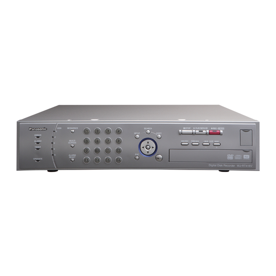
WJ-RT416 is shown above.
Before attempting to connect or operate this product,
please read these instructions carefully and save this manual for future use.
No model number suffix is shown in this Operating Instructions.
Advertisement
Table of Contents

Related Manuals for Panasonic WJ-RT416


Summary of Contents for Panasonic WJ-RT416
-
Page 1: Installation Guide
Model Nos. WJ-RT416V FW D SKI P WJ-RT416 is shown above. Before attempting to connect or operate this product, please read these instructions carefully and save this manual for future use. No model number suffix is shown in this Operating Instructions. - Page 2 If you lose the fuse cover the plug must not be used until a replacement cover is obtained. A replacement fuse cover can be purchased from your local Panasonic Dealer. IF THE FITTED MOULDED PLUG IS UNSUITABLE FOR THE SOCK- ET OUTLET IN YOUR HOME THEN THE FUSE SHOULD BE REMOVED AND THE PLUG CUT OFF AND DISPOSED OF SAFELY.
-
Page 3: Class 1 Laser Product
The serial number of this product may be found on the sur- face of the unit. You should note the serial number of this unit in the space provided and retain this book as a permanent record of your purchase to aid identification in the event of theft. Model No. -
Page 4: Limitation Of Liability
Limitation of liability THIS PUBLICATION IS PROVIDED "AS IS" WITHOUT WAR- RANTY OF ANY KIND, EITHER EXPRESS OR IMPLIED, INCLUDING BUT NOT LIMITED TO, THE IMPLIED WAR- RANTIES OF MERCHANTABILITY, FITNESS FOR ANY PAR- TICULAR PURPOSE, OR NON-INFRINGEMENT OF THE THIRD PARTY’S RIGHT. -
Page 5: Important Safety Instructions
Important safety instructions 1) Read these instructions. 2) Keep these instructions. 3) Heed all warnings. 4) Follow all instructions. 5) Do not use this apparatus near water. 6) Clean only with dry cloth. 7) Do not block any ventilation openings. Install in accordance with the manufacturer's instructions. 8) Do not install near any heat sources such as radiators, heat registers, stoves, or other apparatus (including amplifiers) that produce heat. -
Page 6: Table Of Contents
Limitation of liability ... 4 Disclaimer of warranty ... 4 Important safety instructions ... 5 Precautions ... 7 Preface ... 9 Features ... 9 About these operating instructions ... 10 Trademarks and registered trademarks ... 10 Major operating controls and their functions ... 11 I Front View ... -
Page 7: Precautions
Precautions Refer all work related to the installation of this product to qualified service personnel or system installers. When the model in use is the NTSC model, connect the unit to a 120 V AC power source. When the model in use is the PAL model, connect the unit to a 220 - 240 V AC power source. - Page 8 Prevent condensation from forming on the surface of the hard disk. If this happens, do not turn on the power of the recorder and leave the recorder for around 2 hours. Wait until the dew evaporates in any of the following cases: •...
-
Page 9: Preface
Preface The Digital Disk Recorder WJ-RT416 is designed for use within a surveillance system. The digital disk recorder is a recording device using a hard disk drive to record pictures of surveillance cameras instead of using videotapes so that pictures record- ed by repeated overwriting will not experience deterioration of the recorded picture quality. -
Page 10: About These Operating Instructions
About these operating instructions There are 2 sets of operating instructions for the WJ-RT416 as follows. • Installation Guide (this book) • Operating Instructions (PDF) of the monitoring software The "Installation Guide" contains descriptions of how to install/connect this unit, and descriptions of how to operate this unit with the buttons on the front panel. -
Page 11: Major Operating Controls And Their Functions
• To move the cursor when operating the setup menu. When a user is currently logged in the recorder, the indicator on the button will light blue. STOP PLAY PAUSE REC STOP SKIP – Digital Disk Recorder WJ-RT416 Inside the cover !9 @0 COPY2... - Page 12 !4 Escape button (ESC) Press this button to mute audio when displaying live/recorded images. When operating the setup menu, press this button to cancel the settings currently being edited and go back to the previous page. !5 Set button (SET) Press this button to determine the settings when operat- ing the setup menu.
-
Page 13: I Rear View
I Rear View e r ty RS485(CAMERA) AUX IN SERIAL AUDIO OUT MONITOR1 MONITOR2 q Audio out connector (AUDIO OUT) Audio will be output from this connector. Audio being input to the AUDIO IN/ALARM OUT terminal or to the AUDIO IN connectors will be output. When playing recorded images, audio recorded with the images will be output. - Page 14 !7 Power cord inlet (AC IN) Connect the provided power cord to this inlet. !8 Video in connectors (BNC) (VIDEO IN 1 - 16)/ Video out connectors (BNC) (VIDEO OUT 1 - 16) Images (video signals) from the cameras connected to the VIDEO IN connectors will be looped through to the VIDEO OUT connectors.
-
Page 15: Image Display
Image display When displaying images on a 16-split screen Currently selected camera channel Example: When displaying images from camera channel 1 Information of the recorded images currently being played Cam1 MANUAL NQ PLAY Sep-03-2006 03:00:00PM Time and date of recording Terminal recording Recording icon (indicates... -
Page 16: Startup
Startup Start up the recorder as follows. Connect the power cord to a 120 V AC 60 Hz outlet when the model in use is the NTSC model. When the model in use is the PAL model, connect the power cord to a 220 - 240 V AC 50 Hz outlet. Press the power button to turn on the power of the recorder. -
Page 17: Adjustment Of The Clock Of The Recorder
Adjustment of the clock of the recorder Adjust the clock of the recorder as follows. Check the clock periodically and correct it in the following way if it displays wrong time. It is also necessary to correct the clock after replacing the built-in backup battery. Screenshot 1 Display the setup menu by pressing the SETUP button. -
Page 18: Shutdown Of The Recorder
Shutdown of the recorder To shut down the recorder, do the following. When the manual recording is currently being performed, stop recording. • Hold down the [REC] button for 2 seconds or more. The lit camera selection button indicating the current recording camera channel will go off and all recordings will stop. -
Page 19: Monitor Live Images From The Cameras
Monitor live images from the cameras It is possible to display live images on a single screen or a multi-screen on the monitor. It is also possible to display live images sequentially (sequential display). Display images on a single screen Select a camera channel by pressing the camera selection buttons (1 - 16). -
Page 20: Display Images From The Cameras Sequentially (Sequential Display)
Display images from the cameras sequentially (sequential display) It is possible to sequentially display images from cameras automatically. Images from the cameras will be displayed sequen- tially according to the settings configured in advance. The sequential display can be carried out on a single screen or a 4-split screen. Sequential display on a single screen Make sure that images are displayed not on a 4-split screen, and then press the [SEQUENCE] button. -
Page 21: Recording
Recording Manual recording Start/stop recording manually. Press the [REC] button. • Recording of images from all the camera channels except channels which supply no video input signal will start. The [REC] button and the camera channel selection buttons respective to the channels used for the current recording will light. -
Page 22: Playback
Playback Recorded images can be played as follows. Recorded images will be played on a single screen. Select the desired camera channel by pressing the camera channel selection buttons (1 - 16) or by moving the cursor onto the area respective to the desired camera channel using the arrows button (CDAB) when display- ing images on a multi-screen. - Page 23 Skip playback When the [SKIP s] button is pressed during playback, playback will be skipped to the recorded image of the previous recorded images. When the [SKIP d] button is pressed during playback, playback will be skipped to the recorded image of the next recorded images.
-
Page 24: Search And Play
Search and play It is possible to search the desired recorded images and play them. The search and play can be carried out when displaying images on a single screen. The following is available as the search filter for the search and play. •... -
Page 25: Search And Play With Multiple Search Filters
Search and play with multiple search filters The following search filters are available for search and play. • Camera CH: Only recorded images of the selected camera channels will be searched. • Start/End: Images recorded in the period designated by entering the start time and end time will be searched. •... - Page 26 Screenshot 2 The search result window will be displayed. Search List Cam Quality Start 01-24-2006 10:43:22 01-24-2006 10:43:22 01-24-2006 10:43:22 01-24-2006 10:43:22 01-24-2006 10:43:22 01-24-2006 10:43:22 01-24-2006 10:43:22 01-24-2006 10:43:22 Prev Next Step 3 Move the cursor to the desired recorded images to play. Prev: The previous page will be displayed.
-
Page 27: Alarm Function
Alarm function The recorder will take the alarm action according to the settings when the following events occur. • Terminal alarm: When a signal is supplied from an external device such as a door sensor to the ALARM IN/CONTROL ter- minal, this is stated as an event of a terminal alarm. -
Page 28: Cancel The Alarm Action
(PDF) on the provided CD-ROM for how to configure the settings. • Provide notification of an event occurrence to the PC according to the setting of Panasonic alarm protocol Notification of an event/error occurrence (time and date, event/error type) can be automatically provided to the PC accord- ing to the settings of Panasonic alarm protocol. -
Page 29: Copying (Duplicate)
Copying (Duplicate) It is possible to copy recorded images onto an external recording device (HDD, DVD-R, CD-R, USB memory, etc.) connected to the recorder. It is recommended to make back-up copies on a regular basis for unexpected situations such as malfunction of the HDD. - Page 30 Screenshot 2 The "Copy List" window will be displayed. Copy List Cam Quality Start 01-24-2006 10:43:22 01-24-2006 10:43:22 01-24-2006 10:43:22 01-24-2006 10:43:22 01-24-2006 10:43:22 01-24-2006 10:43:22 01-24-2006 10:43:22 01-24-2006 10:43:22 Total:20 Size:12.08GB Copy A:Data Only Copy B:Copy with Viewer Prev Next Copy A Notes:...
-
Page 31: Log In As A Different User
Log in as a different user To log in as a different user, log out first and log in again. When logged out, the buttons on the front panel will be locked and the password entry window will be displayed when any of the buttons is pressed. -
Page 32: Log In
Log in Screenshot 1 When logged out once and press any of the buttons on the front panel, the password entry window will be displayed. Input Password Operation restriction differences between the user levels Live image display Camera channel selection/ Multi-screen selection Camera channel selection using the cursor... -
Page 33: Disk Management
Disk management It is possible to format the built-in HDDs and restore HDD management information (list information of recorded images). Check HDD information HDD information (total disk size, used disk size, hour meter) and time and date of the latest/oldest data on the HDD can be checked as follows. - Page 34 Notes: • The used disk space will not be displayed as "0 GB" even when no data is saved on the disk since the sys- tem uses some of the disk space. • HDD6 is not provided for the WJ-RT416V. Screenshot 4 The "Disk Information"...
-
Page 35: Format The Hdd
Format the HDD There are two ways of how to format the HDD as follows. • Format only the selected HDD • Format all the HDDs simultaneously Format only the selected HDD Screenshot 1 Display the "Disk Management" window ( page 33). Disk Management Capacity Used... - Page 36 Stop power supply to the HDD When replacing the HDD, it is necessary to stop power supply to the HDD in advance. Contact your dealer when it is necessary to replace the HDD. Screenshot 1 Display the "Disk Management" window ( page 33). Disk Management Capacity Used...
- Page 37 Restore HDD management information When information of recorded images on the HDD and HDD management information (list information) do not match, restore the HDD management information. Restore of HDD management information sometimes resolves problems such as a playback failure. Screenshot 1 Display the "Disk Management"...
-
Page 38: Operate The Recorder Using A Pc
Operate the recorder using a PC It is possible to configure the settings and operate the recorder on a network using the monitoring software when it is installed on the PC from the provided CD-ROM. The following are some functions and their features of the monitoring software, and the system requirements for a PC on which the software can be installed. -
Page 39: Installation
Installation HDD safety mode When installing the recorder in the rack without turning the power of the recorder off, activate the HDD safety mode. When the HDD safety mode is activated, the power of the all HDDs will be off. (Recording and playback will be forcibly can- celed.) At the default, the recorder will start up in the HDD safety mode to protect the HDDs from shock, vibration, etc. -
Page 40: Hdd Replacement
HDD replacement When the indication "Disk Access Error", "Data Error", "Disk Unacknowledged" or "Disk Type Unfitting" is displayed, it is possi- ble to replace the HDD without stopping the operation of the recorder. (A new HDD must be the same model as of the HDD to be replaced with.) It is necessary to stop the power supply to the HDD before starting the HDD replacement. -
Page 41: Rack Mounting
Rack mounting Use an EIA-standard 19" rack (depth: 550 mm or more). Note: It is necessary to procure four optional rack mount screws (W2-MSS/5008 or M5 x12). Remove the five rubber feet from the bottom of the recorder using a flathead screwdriver. Place the provided rack mounting brackets on both sides of the recorder and tighten with the eight provided screws. -
Page 42: Connection
REC STOP SETUP COPY MULTI SKIP SCREEN – 10/0 ALARM RESET Digital Disk Recorder WJ-RT416 Microphones Amplifier Video monitor Connect the video monitor to the monitor 1 connector. External recording device connected to the COPY1 (rear) or COPY2 port (front) -
Page 43: Connection With Rs485 Cameras
Connection with RS485 cameras RS485 cable (WV-CA48/50) Unit number: 12 Unit number: 11 Termination: ON Termination: OFF 4-wire connection 4-wire connection Combination cameras (RS485 compatible) Important: The maximum length of the cable to be used to connect between a RS485 camera and the recorder is 1 200 m. Note: Contact your dealer when connecting cameras using the 2-wire connection. -
Page 44: Connection With Ps·data Systems
Connection with PS·Data systems This is an example of connection when the unit is used together with the PS·Data devices. If a connected system controller is PS·Data compatible, it is possible to operate this unit or connected devices using the sys- tem controller. - Page 45 When installing this unit between a controller and a system device UNIT ALARM POWER ALARM RESET SUSPEND SET UP ALARM SUSPEND Data Multiplex Unit WJ-MP204 Coaxial communication unit Termination: ON Unit Address : 2 RS485 cable Mode selection DIP switches RS485 cable RS485(CAMERA) AUX IN...
-
Page 46: Connection With A Pc
Gateway address: 192.168.0.1 LAN cable (10BASE-T/100BASE-Tx, category 5, cross) SEARCH STOP PLAY PAUSE REC STOP SETUP COPY SKIP – Digital Disk Recorder WJ-RT416 SEARCH STOP PLAY PAUSE REC STOP SETUP COPY SKIP – 10/0 Digital Disk Recorder WJ-RT416 LAN cable... -
Page 47: Dip Switch Setting
When connecting to the system device and this unit is connected as the end of the PS·Data connection, set mode selection DIP switch 1 to "ON". Broadband router A (WAN → WJ-RT416) TCP/UDP port: 2000 (configured on the WJ-RT416) STOP PLAY... - Page 48 Mode selection DIP switch: The dip switch positions are defined by the attribute of the unit connected to the system’s DATA terminal. Machine connected to the DATA port DIP switch 1 DIP switch 2 Controller System Device...
-
Page 49: Rs485 (Camera) Port
RS485 (CAMERA) port When connecting an RS485 camera, connect it to the RS485 (CAMERA) port on the rear of the recorder. RS485(CAMERA) Signal Signal AUDIO IN/ALARM OUT terminal AUDIO IN/ALARM OUT Pin No. Signal Audio input CH7 Audio input CH8 Audio input CH9 Audio input CH10 Audio input CH11... -
Page 50: Alarm In/Control Terminal
ALARM IN/CONTROL terminal Pin No. Signal Alarm input CH1 Alarm input CH2 Alarm input CH3 Alarm input CH4 Alarm input CH5 Alarm input CH6 Alarm input CH7 Alarm input CH8 Alarm input CH9 Alarm input CH10 Alarm input CH11 Alarm input CH12 Alarm input CH13 Alarm input CH14 Alarm input CH15... -
Page 51: Setup Menu
Setup menu It is necessary to configure the settings on the setup menu in advance to operate the recorder. Display the setup menu on the monitor and configure the settings. Setup menu chart Setup item System Setup Recording Setup Common Setup Manual Rec. -
Page 52: Basic Operation Of The Setup Menu
Basic operation of the setup menu Screenshot 1 Display the setup menu by pressing the SETUP button. Setup Menu System Setup Recording Setup Event Setup Display Setup Camera Control Setup Communication Setup User Management Maintenance Screenshot 2 The submenu of the selected setup item will be displayed. (Example: When "Recording Setup"... -
Page 53: Configure The System Settings [System Setup]
Configure the system settings [System Setup] Configure the settings relating to the system such as the clock adjustment, language setting, auto login user, etc. System Setup Month-Day-Year Time & Date 10-22-2006 11:30:30 (Time Zone) GMT-5:00 Language English Auto Login User Manager Auto Logout Time 600 Sec... - Page 54 Auto Adjust Time When signal is input to the time adjust input terminal on the rear of the recorder ( page 50), the clock of the recorder will be set to "00" minute. The clock will be set to "00" minute only when signal is input at the following time.
-
Page 55: Configure The Recording Settings [Recording Setup]
Configure the recording settings [Recording Setup] Configure the settings for recording (manual recording, timer recording, alarm recording). Recording Setup Common Setup Manual Rec. Setup Timer Rec. Setup q Configure the common recording settings [Common Setup] Configure the basic settings to be applied regardless of the recording type (manual recording, timer recording, alarm record- ing). - Page 56 I Advanced Setup The following window will be displayed when the [SET] but- ton is pressed after moving the cursor onto "Set→". Common Setup (Advanced) Time Per File I Frame Interval Resolution Time Per File Determine the recording time length of the recorded images to be saved as a file.
- Page 57 w Configure the manual recording settings [Manual Rec. Setup] Configure the settings for manual recording that starts recording when the [REC] button is pressed. Manual Rec. Setup Camera No. Rec. Quality SP Fine Rec. Frame Rate Full I Camera No. Select a camera channel to be used for manual recording.
-
Page 58: Configure The Alarm Action Settings [Event Setup]
Configure the alarm action settings [Event Setup] Configure the settings relating to the alarm action that is to be taken at an event occurrence. Refer to page 27 for further information about the event type and the alarm action. Event Setup Common Setup Alarm Rec. - Page 59 w Configure the alarm recording settings [Alarm Rec. Setup] Configure the settings relating to the alarm recording that starts upon an event occurrence. Alarm Rec. Setup Alarm No. 00:00 24:00 00:00 Term Rec. Channel 00:00 24:00 00:00 Rec. Channel Sensitivity Area Setup Set→...
- Page 60 I VMD (Area Setup) Set the VMD area. The following window will be displayed when the [SET] but- ton is pressed after moving the cursor onto "Set". Cursor (red) Green areas (set as the VMD areas) Green area: Set as the VMD area. Clear area: Not set as the VMD area.
-
Page 61: Configure The Display Settings [Display Setup]
Configure the display settings [Display Setup] Display Setup Status Display Sequence Dwell Camera Allocation Setup Cancel I Status Display Determine which information is to be displayed. All: All information will be displayed. Status: The status icons and time and date will be dis- played. -
Page 62: Configure The Settings Relating To The Camera Control [Camera Control Setup]
Off: Do not control the cameras. Default: Coax (Cam 1 - 4), PSD (Cam 5 - 16) I Protocol Select "Panasonic" when "RS485" is selected for "Type". Default: Panasonic I Compensation Select the cable length when "Coax." is selected for "Type". -
Page 63: Configure The Settings Relating To Communications With Other Devices [Communication Setup]
Configure the settings relating to communications with other devices [Communication Setup] It is necessary to conform the setting such as the communication protocol and the line speed when connecting an external device such as a system controller to the DATA port or the RS485 port. It is also necessary to configure the network settings such as the IP address and the gateway address to operate the recorder using a PC via a network. - Page 64 I Advanced Setup The following window will be displayed when the [SET] but- ton is pressed after moving the cursor onto "Set→". Network Setup (Advanced) IP Address (Primary) ---.---.---.--- IP Address (Secondary) ---.---.---.--- Server Port 02000 w Configure the RS485 settings [RS485 Setup] Configure the RS485 settings.
- Page 65 I Baud Rate Select the communication speed for data transmission with a connected device from the following. 2 400/4 800/9 600/19 200/38 400 bps Default: 9 600 I Data Bit The data bit will be displayed. It is impossible to change the value for this setting.
-
Page 66: Configure The Settings Relating To User Information [User Management]
Configure the settings relating to user information [User Management] User information such as the user level, password, etc. can be managed (registration, editing, deletion). User Management User Level Setup Password Logout q Restrict the operable functions [User Level Setup] Configure the operational level of "operator" and "viewer" for each channel. User Level Setup Camera No. - Page 67 w Set the password [Password] Set the password for each user level. Password entry will be required to log in the recorder. Password Manager 1 ******** Manager 2 ******** Manager 3 ******** Manager 4 ******** Operator Viewer Password Operator 1 ****** Operator 2 ******...
-
Page 68: Maintenance Functions [Maintenance]
Maintenance functions [Maintenance] Configuration of the settings relating to the HDDs, the system information check, log check, and initialization of the settings are available. Maintenance Alarm Log Error Log System Information Current Recording Setting Disk Management Online User Information Factory Default Reboot System Advanced Information q Check the alarm log [Alarm Log]... - Page 69 e Check the system information [System Information] System information such as the firmware version, MAC address, etc. can be checked. System Information Firmware Version *.** MAC Address AA:BB:CC:DD:EE:FF Video Format NTSC Optional Board Coax1 Current Temperature 28 degC/82 degF Highest Temperature 37 degC/98 degF 10-05-2006 10:00:00 Return...
- Page 70 y Check the user information of the current login user [Online User Information] By using the monitoring software, it is possible to check user information of the online users such as user name, operational status and IP address. Online User Information User Name Type Manager 1...
- Page 71 o Check the detailed information [Advanced Information] Operation log and access log can be checked and the firmware can be upgraded. The following window will be displayed when the [SET] button is pressed after moving the cursor onto "Set". Advanced Information Operation Log Access Log Firmware Update...
- Page 72 Step 1 Save the firmware onto the following directory of an external recording device, and then connect the external recording device to the recorder. [Drive](Copy Data):\Panasonic\RT\Firmware\rt4flash.img Step 2 Move the cursor onto "Firmware Update", and then press the [SET] button.
-
Page 73: Operation Using The System Controller
To operate the unit using the system controller WV-CU650, configure the settings required to use a PS·Data compatible system controller in advance. I Operation using the WV-CU650 Operation WJ-RT416 Open/close the "Setup Menu" Select an item Change the set parameter –... - Page 74 Camera selection buttons Select a camera 1 - 16 Select a multi-screen Select a camera channel Sequential display ON Display the copy window Close the copy window Mute ON/OFF WJ-RT416 WV-CU650 PLAY/ PAUSE PLAY/PAUSE STOP STOP PLAY/ PAUSE PLAY/PAUSE –...
-
Page 75: Troubleshooting
Troubleshooting Before asking for repairs, check the symptoms with the following table. Contact your dealer if a problem cannot be solved even after checking and trying the solution or a problem is not described below, and when having a problem with installations. Symptom Cannot turn on the power of the recorder. - Page 76 Symptom The recorder starts up in the HDD safety mode when turning on the power. Cannot start recording. Cannot play recorded images. Cannot operate the camera. No alarm action is taken. No notification mail is sent. The clock does not keep cor- rect time.
- Page 77 Inspect the power cord, power plug and connectors periodically. Symptom Cannot copy recorded images onto a disk using the internal CD/DVD drive. (Only when using the WJ-RT416V.) The recorder needs much time to start up. The power cord insulation is damaged.
-
Page 78: Specifications
Image compression method Resolution Rec. Frame Rate 120 V AC, 60 Hz (NTSC model), 220 - 240 V AC, 50 Hz (PAL model) WJ-RT416, WJ-RT416K: 110 W WJ-RT416V, WJ-RT416VK: 120 W 5 °C - 45 °C {41 °F - 113 °F}... -
Page 79: Standard Accessories
Power cable for PAL model ... 2 pcs. HDD mounting screw, sleeve, damper for the WJ-RT416K ... 24 pcs. each HDD mounting screw, sleeve, damper for the WJ-RT416 ... 20 pcs. each HDD mounting screw, sleeve, damper for the WJ-RT416VK ... 20 pcs. each HDD mounting screw, sleeve, damper for the WJ-RT416V ... -
Page 80: Information On Disposal For Users Of Waste Electrical & Electronic Equipment (Private Households)
Unit Company of Panasonic Corporation of North America Security Systems www.panasonic.com/security For customer support, call 1.877.733.3689 Executive Office: Three Panasonic Way 2H-2, Secaucus, New Jersey 07094 Zone Office Eastern: Three Panasonic Way, Secaucus, New Jersey 07094 Central: 1707 N. Randal Road, Elgin, IL 60123 Southern: 1225 Northbrook Parkway, Suwanee, GA 30024 Western: 6550 Katella Ave., Cypress, CA 90630...
Need help?
Do you have a question about the WJ-RT416 and is the answer not in the manual?
Questions and answers