Advertisement
Available languages
Available languages
Quick Links
Quick Start Guide
Warning Device NVD-111
Sludge Level Sensor FAU-104
Pepperl+Fuchs GmbH
Lilienthalstrasse 200
68307 Mannheim, Germany
Tel. +49 621 776-0
Fax +49 621 776-1000
Document No.: 45-4164A
Edition: 01/2014
Copyright Pepperl+Fuchs
www.pepperl-fuchs.com
Intended Use
Warning Device NVD-111
The warning device is a compact alarm system for monitoring one sensor in a
sludge tank of a car wash equipment.
The warning devices must only be installed in a suitable control cabinet or
NVO5-KV installation housing.
The warning device was designed for the monitoring of the sludge level, i. e. an
alarm if a certain limit of maximum receptacle capacity of sludge has been
reached.
Sludge Level Sensor FAU-104
The sludge level sensor FAU-104 (referred to as "sensor" in the following
sections) is a suspended sensor for monitoring sludge levels.
The sensor must always be connected to an warning device of type NVD-111.
Components
Description
Type code
Warning device, 230 V AC
Sludge level sensor
Mounting set for one sensor
Cable connector for one sensor
Design and Dimensions
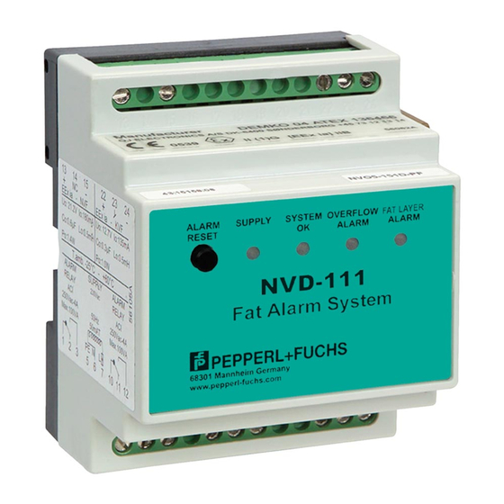
Warning device NVD-111
58
70
1
5
ALARM
SUPPLY
SYSTEM
OVERFLOW
FAT LAYER
RESET
OK
ALARM
ALARM
NVD-111
54
Fat Alarm System
68307 Mannheim Germany
www.pepperl-fuchs.com
4
3
2
1
DIP switches
2
LEDs
3
Connections for power supply and potential-free contacts
4
Reset button
5
Sensor connections
Sludge level sensor FAU-104
ENG
2
Ø38
1
4
66
1
Lower section
2
Cable
3
Reflectors
4
Switch point
Installation
Connection
Connecting and configuring the warning device with sludge level
sensor FAU-104
1
bn
bu
18
20
22
24
3
1
2
3
4
5
6
OFF
ON
NVD-111
FAU-104
NVO5-B
LAL-SK2
1 2 3
5 6 7
10 11 12
230 V AC
4
1
Sludge level sensor connection
2
Sludge level sensor FAU-104
3
DIP switches
4
Power supply
bu blue
bn brown
Commissioning
Configuring the Warning Device using DIP Switches
Often, mud and dirt particles are stirred up by pump operation in the sludge
tank. These mud and dirt particles can cause a false alarm for the sludge level
sensor. Therefore, it is possible to set two possible monitoring states for the
sludge level sensor on the warning device via the setting of DIP switch 1
(reaction time of the sludge level sensor).
Switch setting ON – operating mode
•
The reaction time for detection of a sludge level is 24 hours (warning device
in normal mode, green LED "SYSTEM OK" lights up). Only after the sludge
level sensor has constantly been in a sludge level for 24 hours is the alarm
status displayed via the LED "SLUDGE LEVEL ALARM" and, if applicable,
an acoustic alarm triggered and relay activated.
•
The reaction time for detection of water is 1 hour (warning device in alarm
mode, red LED "SLUDGE LEVEL ALARM" lights up). Only after the sludge
3
level sensor has constantly been in water for 1 hour does the LED
"SLUDGE LEVEL ALARM" go out and the LED "SYSTEM OK" flashes.
Switch setting OFF – service/test mode
•
After switching on the warning device or after switching the DIP switch from
ON to OFF, an alarm is detected immediately and the warning device
displayed. The DIP switches are located on the right of the device.
Operation
Alarm Signals
The warning device indicates an alarm status or sensor fault both visually and
acoustically. The "SLUDGE LEVEL ALARM" LED is illuminated until the system
returns to a normal status.
LED
Yellow LED "SUPPLY"
Green LED "SYSTEM OK"
7
8
Red LED
2
"SLUDGE LEVEL ALARM"
Status
Meaning
lights up
The device is connected to the power
supply. The device is in operation.
flashes briefly
Prerequisite DIP switch 1 = ON
In this mode, a brief flash of the "SUPPLY"
LED indicates that a change in status has
been detected by the sensor.
lights up
No errors or alarms active – normal
operation
flashes
No alarm or error active, there was an
alarm or error in the past.
lights up
Alarm active, sludge level sensor is
covered with sludge.
flashes
Internal sensor error, lead breakage or
short-circuit
Advertisement

Subscribe to Our Youtube Channel
Related Manuals for Pepperl+Fuchs NVD-111


Summary of Contents for Pepperl+Fuchs NVD-111
- Page 1 Prerequisite DIP switch 1 = ON The sensor must always be connected to an warning device of type NVD-111. In this mode, a brief flash of the “SUPPLY” LED indicates that a change in status has been detected by the sensor.
- Page 2 Lyser Forsyningsspænding på apparatet. overvågning af slamhøjden i slambeholdere for bilvaskeanlæg. Apparatet er i drift. Føleren skal altid tilsluttes til et alarmrelæ af typen NVD-111. Blinker et Forudsætning DIP-switch 1 = ON øjeblik I denne tilstand indikerer et kort blink på...
Need help?
Do you have a question about the NVD-111 and is the answer not in the manual?
Questions and answers